3 Hazen and Sawyer, P.C., 4000 Hollywood Blvd 750N, Hollywood, Florida, USA ... 5 The Fluid Group, The Magdalen Centre, Robert Robinson Avenue, The ...
WEFTEC 2012
Computational Fluid Dynamics (CFD): What is Good CFDModeling Practice and What Can Be the Added Value of CFD Models to WWTP Modeling? Ingmar Nopens1, Damien J. Batstone2, Alonso Griborio3, Randal Samstag4, Ed Wicklein4 and Jim Wicks5 1
BIOMATH, Department of Mathematical Modelling, Statistics and Bioinformatics, Ghent University, Coupure links 653, 9000 Gent, Belgium 2 Advanced Water Management Center, University of Queensland, 4072, Brisbane, Australia 3 Hazen and Sawyer, P.C., 4000 Hollywood Blvd 750N, Hollywood, Florida, USA 4 Carollo Engineers, Seattle, Washington, USA 5 The Fluid Group, The Magdalen Centre, Robert Robinson Avenue, The Oxford Science Park, Oxford OX4 4GA, UK
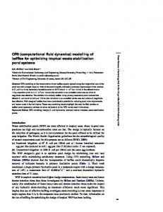
ABSTRACT CFD modeling is increasingly used in the wastewater treatment (WWT) field, both in academia and practice, with a significant increase in the last 5 years. However, the future use of CFD models and their added value to the wastewater field will be very much dependent on their proper use. As was recently established for biokinetic models, this requires a code of Good Modeling Practice (GMP) for CFD as well. Discussions towards GMP for CFD and potential current and future uses and challenges were subject for thorough discussion at a dedicated workshop at the 3rd IWA/WEF Wastewater Treatment Modeling Seminar held in Mont-SainteAnne (Canada). This paper summarises the major outcomes of that workshop. KEYWORDS: computational fluid dynamics; good modeling practice INTRODUCTION CFD models have been extensively used in a wide variety of engineering disciplines including general environmental engineering, chemical engineering, and mechanical/aerospace engineering. Over the last 15 years, there has been a steady increase in CFD modeling in the wastewater treatment (WWT) field, both in academia and practice, with a significant increase in the last 5 years. The general growth of CFD for practical applications has seen its use by wastewater design engineers in various areas. As illustrated in Figure 1, nearly all unit processes used in wastewater treatment facilities have been modelled by using CFD. Furthermore, also other types of systems like MBR (Brannock et al., 2010) and waste stabilisation ponds (Alvarado Martinez et al., 2012) have been modelled with CFD. Despite this growth, the application of CFD has not reached comparable levels compared to other application fields where it has become standard for prototyping and evaluating equipment to assess factors which would not normally be evaluated in any other way. There are a number of barriers to widespread application of CFD based analysis of wastewater treatment systems. One is its limited penetration within the educational and academic sector. Typical users are either mechanical, or chemical engineers, that received a supplementary training in Environmental Engineering, or Environmental Engineers that took training (sometimes based on self-study) in CFD from books, through colleagues or by taking training courses provided by commercial CFD software manufacturers. Another is the relatively high cost of commercial CFD software. Only large environmental engineering consulting companies often feel that their work can justify this cost. Despite the current successful spread and usage of CFD modeling, there is also a potential danger in its misuse, due to either poor model selection and setup, and interpretation of results. Misuse leads to bad designs or processes that result in
Copyright ©2012 Water Environment Federation. All Rights Reserved. 7400
WEFTEC 2012
suboptimal hydraulic design, contributing to distrust of CFD models in the WWT field. While there are several textbooks available on the general use of CFD modeling, currently there is no targeted textbook or scientific report available that addresses the proper use of CFD for wastewater treatment. The WWTmod2012 workshop was meant to be a first step towards such a technical report as it focused on achieving consensus on good modeling practice when developing and using CFD WWT models, including proper interpretation of simulation results. A second important objective of the workshop was to discuss how CFD models can be useful for WWT engineering practice to date and how they can further be developed to serve WWT modeling in general. This paper is therefore broken down in two parts, a first one addressing GMP and a second one outlining ideas towards future use of CFD models in WWT.
Figure 1. Overview of WWT unit processes that have in the past been modeled using CFD RESULTS AND DISCUSSION Towards good modeling practice for CFD Good modeling practice has recently received ample attention in WWT modeling, more specifically with regard to biokinetic models. In that respect the IWA Task Group on Good Modeling Practice released a detailed report (Rieger et al., 2012). The typical ingredients of good modeling practice for any modeling exercise are illustrated in Figure 2a. It consists of (1) clearly defining the objective of the modeling work with all parties involved; (2) the collection of data, defining the model configuration (e.g. level of detail of the model) and simulation settings; (3) running the simulations (steady state, dynamic) and (4) post-processing, calibration and validation. After these steps, either the objective is met or the developed model is ready to be used to explore the answer to the objective with additional methods such scenario analysis. However, setting up a CFD model includes additional considerations compared to developing a biokinetic model. A first important addition is the fact whether the objective justifies and really necessitates the use of a CFD model for the purpose. Secondly, a CFD model may or may not undergo a calibration step as the degrees of freedom that could be used to fine-tune the model may be limited. On the other hand, a CFD model may be used in the context where important parameters are unknown, and calibration and validation is absolutely required. In contrast, it may also be used where the analysis is of fundamental interactions between geometry, fluid properties, and the hydraulic model. In this case, validation is not essential, since the underlying physics and geometry are known. Furthermore, it should be noted that data collection for validation is both time consuming and resource intensive as it typically requires advanced measurement techniques. Mostly velocity measurements such as Acoustic Doppler Velocimetry (ADV) or Laser Doppler Velocimetry (LDV) are used, which require specific skills and expertise to conduct (Vanrolleghem et al., 2006). Additionally, also spatial profiling of certain components within the reactor (e.g. dissolved oxygen) and reactive tracer methods have been reported (Gresch et al., 2010). Usually, the validation is performed by visual inspection of 2-3D graphs of
Copyright ©2012 Water Environment Federation. All Rights Reserved. 7401
WEFTEC 2012
experimental data and model predictions, which can be subjective, as it involves pattern recognition rather than the normal comparison of model error using e.g. an objective function. Verification by solids and dye profiling (tracer test) is a relatively inexpensive and welldocumented procedure, however, and can be used for verification of solids transport modeling for many wastewater treatment applications (Bender and Crosby, 1984). Next to these differences in the generic methodology, the different steps in the procedure also contain differences related to the specificities of CFD. This is the case for whatever unit is being modelled. These steps are outlined in Figure 2b and further briefly discussed.
a) b) Figure 2. a) Typical ingredients of good modeling practice and b) specific ingredients of good modeling practice when applied to a CFD modeling study
With regard to the model configuration, several crucial choices need to be made which have a significant impact on the computational burden of the model and the correctness of the predictions. In this respect, the objectives should be accurately defined and the system analysed as to what level of detail a model is required. A first choice is the dimensionality of the model (2-3D). A 3D-problem is not particularly more complex in use, but one should realize that this has significant impact on the computational requirements. Hence, one should check whether the assumptions made when modeling in 2D are too harsh for the objective to be met. If not, a 2D model might be able to provide the answer to the objective in a fraction of the time compared to 3D. It should be noted that there are a large number of opportunities to infer 3D outcomes from 2D geometry by for example, locating areas of axial symmetry. A second important choice is the number of different phases to be used. In WWT we are typically dealing with liquid flows in which solids are dispersed and, moreover, in aerated zones a gas phase is introduced. Furthermore, dissolved components are present too. There are several ways to account for dispersed components, each coming at a certain cost. The easiest approach is to model only one phase and assume the solids to follow the advective flow (i.e. by using a separate solids transport equation). The advantage of this approach is that a large body of data can be used to model solids settling. Another way is to use a two-phase approach which tracks the mass and momentum balances (Navier-Stokes equations) for both phases and includes momentum transport between both phases (normally through a slip model). This approach may have limited validity, especially when individual fluid properties are not known (e.g., for solid phases). A compromise solution is provided by the so-called “mixture” model. A disadvantage of the standard mixture model approach is that it relies on input of a single particle diameter for calculation of settling velocity by the Stokes equation. This is unrealistic for most wastewater applications where a wide range of particle diameters are present and which change as they flow
Copyright ©2012 Water Environment Federation. All Rights Reserved. 7402
WEFTEC 2012
through a tank (Wicklein and Samstag, 2009). When it comes to dissolved components, these are assumed to just follow the fluid motion and are usually modeled as separate species through species equations that predict local concentrations accounting for both advection and diffusion. A third choice to be made is with respect to material properties that impact fluid properties such as density and viscosity, which can be chosen independently for all phases that are modeled. With respect to solids, density of the fluid is fundamentally MLSS dependent, and viscosity is normally related to solids also. The impact of solids on density is relatively straightforward to include (being an ideal mixture). Recent research indicates that neutral density analysis of activated sludge tanks can dramatically over-predict the degree of mixing (Samstag et al, 2012). Some models have been reported in literature, but there is a lack of consensus, particularly at higher solids concentrations. The impact of solids on viscosity, although been studied quite often, is still less well defined. A fourth choice is whether additional models apart from the CFD are required. If conversion of dispersed and dissolved components is occurring (and of interest to either hydraulics, rheology, or the process itself), conversion terms need to be added to their respective scalar equations. If settling is to be modeled, a settling velocity in the direction of gravity should be introduced. The next step in the protocol concerns data collection. For CFD models, accurate geometric information is required as this can have a significant impact on flow behavior, and often the model objective is to assess the impact of geometry on fluid hydraulics. If available, CADdrawings can be imported in most software tools. If not, it is advised to spend ample time on collecting this data accurately (and properly validate existing data). Next to this, information on incoming and outgoing flows from the studied system as well as concentrations of important components should be collected. If more rigorous models will be used for certain material properties (density, viscosity), data to calibrate those need to be collected as well. The data collected in the previous step now allows, after further system assessment, to decide on the fluid kinetic model. Based on the Reynolds number it should be decided whether the flow is in a laminar or turbulent regime. The second is more computationally complex, requiring calculation of additional turbulent model field states (e.g., - model variables, as well as the standard velocity and pressure fields). Finally, in this step boundary conditions for all incoming and outgoing flows (for each phase), walls, and surfaces, need to be set. The latter also includes boundary conditions for the turbulent quantities if turbulence appears to be important. All of these boundary conditions can be steady state or dynamic. In a final step, the geometry needs to be divided into nodes, a process referred to as “meshing”. The latter is a complex problem in itself and has many degrees of freedom with respect to mesh type, number of nodes, spatially dependent mesh coarseness, etc. As a last step, the type of solvers for the different equations and their settings can be chosen along with the rules for convergence which can be set by the user. The latter will determine the speed of simulation, its accuracy and the fact whether useful or useless results will be obtained. This final step is iterative as usually a grid independency check is performed in order to verify whether the grid coarseness has an effect on the solution. A coarse grid has a lower level of inherent stability (and higher degree of numerical diffusion) with respect to solution, while a fine grid will be more stable, but will be more difficult to solve, both because of the increased number of states, but also because of an increased model stiffness (order of magnitude in model processes). Current and future added value of CFD The current portfolio of CFD models in the field of WWT is illustrated in Figure 3. Next to “plain CFD” which simply computes (single phase) flow patterns, different ingredients can be added resulting in an “extended CFD” approach. Some of these are more straightforward than others and are recommended to be used as state of the art (e.g. density, soluble transport). Others have not reached consensus yet and are being debated in literature (e.g. rheology, solids transport, flocculation). They should be used with caution. Efforts to combine CFD with ASM
Copyright ©2012 Water Environment Federation. All Rights Reserved. 7403
WEFTEC 2012
models are ongoing as well (e.g. Sobremisana et al., 2011).
Figure 3. Current portfolio of CFD models in the field of WWT To date CFD models have primarily been used for design analysis and troubleshooting, mainly due to the computational effort. However, more frequent use of CFD and the accumulation of knowledge should increasingly allow for optimization of design and operation. This has, in the past, already been applied to secondary sedimentation (e.g., Griborio et al., 2006, Xanthos et al., 2011) and mixing (Samstag et al., 2012), but will also be true for other processes. Optimization can both be in terms of process performance (e.g. improved conversion through better mixing) as well as in energy reduction (e.g. smarter location and operation of impellers and aerators). The time-scale when these benefits can become available really depend on the complexity of the system and how much effort was already invested into it in the past. An overview of expectations is given in Table1. Table 1. Time-scale of expected different developments using either plain or extended CFD Timing / CFD type Plain CFD Extended CFD Short term Flow splitters and combiners Secondary clarifiers Medium to long term Mixing of tanks Coupled biokinetics Optimisation of heat transfer Environmental dispersion Two-phase models Membrane fouling Aeration and gas-liquid transfer Integration of CFD and extended plant wide models Next to the use of CFD as stand-alone tool in system optimization, a second route will be to use CFD as a means to build up knowledge which can then serve to improve the models we are currently using. The first examples have been reported in literature where CFD models are used to build somewhat more detailed mixing models called “compartmental models” (compared to the current practice of tanks-in-series) (Le Moullec et al., 2011, Alvarado Martinez et al., 2012). This is likely required to restore the balance in complexity between different submodels used in current WWT modeling. In this way CFD models clearly have a complementary and supporting role to play in WWT modeling and by no means will replace them in the near future.On the contrary, they are an important tool to further extend our knowledge and further exploit the power of mathematical modeling for WWT systems. CONCLUSIONS AND PERSPECTIVES
Copyright ©2012 Water Environment Federation. All Rights Reserved. 7404
WEFTEC 2012
The potential for CFD in WWT applications is tremendous. However, to date, this potential has not been fully exploited. One of the reasons, next to training of people, is the lack of a good guidance with respect to good modeling practice in water and wastewater. This should cover the complete process from objective definition through to solution and visualisation. In this paper, we have tried to briefly outline the main differences with GMP of biokinetic models and the specificities of developing CFD models. Furthermore, an overview of the current and future potential of CFD in WWT is provided. ACKNOWLEDGMENTS Ingmar Nopens thanks the Flemish Fund for Scientific Research (Project G.A051.10). REFERENCES Alvarado Martinez, A., Vedantam, S., Goethals P., and Nopens, I. (2012). Compartmental Models to Describe Hydraulics in Full-scale Waste Stabilization Ponds. Water Research, 46(2), 521-530. Bender, JH, and Crosby, RM, "Hydraulic Characteristics of Activated Sludge Secondary Clarifiers," Project Summary, US EPA 600/S2-84-131 (1984). Brannock, M., Wang, Y. and Leslie, G. (2010). Mixing characterisation of full-scale membrane bioreactors: CFD modeling with experimental validation. Water Research, 44(10), 31813191. Gresch, M., Braun, D., and Gujer, W. (2010). Using reactive tracers to detect flow field anomalies in water treatment reactors. Water Research, 45(5), 1984-1994. Griborio, A., and McCorquodale, J.A (2006). Optimum design of your center well: Use of a CFD model to understand the balance between flocculation and improved hydrodynamics. In: Proceedings of the 79th Annual Conference and Exposition, Dallas, TX, October 21-26, 2006. Le Moullec, Y., Potier, O., Gentric, C. and Leclerc, J P. (2011). Activated sludge pilot plant: Comparison between experimental and predicted concentration profiles using three different modeling approaches. Water Research, 45(10), 3085-3097. Rieger, L., Gillot, S., Langergraber, G., Ohtsuki, T., Shaw, A., Takacs, I. and Winkler, S. (2012). Guidelines for using Activated Sludge Models. IWA Scientific and Technical Report. Technical Report. IWA Publishing. London. Samstag, R.W., Wicklein, E.W., Reardon, R.D., Leetch, R.J., Parks, R.M., and Groff, C.D. (2012). Field and CFD Analysis of Jet Aeration and Mixing. In: Proceedings of the 84th Annual Water Environment Federation Technical Conference & Exposition, New Orleans, LA, October, 2012. Sobremisana, A.P., Ducoste, J.J, and de los Reyes, F.L.III (2011). Combining CFD, Floc Dynamics and Biological Reaction Kinetics to Model Carbon and Nitrogen Removal in Activated Sludge System. In: Proceedings of the 84th Annual Conference and Exposition, Los Angeles, CA, October 15-19, 2011. Vanrolleghem, P.A., De Clercq, B., De Clercq, J., Devisscher, M., Kinnear, D.J., Nopens I. (2006). New Measurement Techniques for Secondary Settlers: A Review. Water Sci. Technol. 53(4-5), 419-429. Wicklein, E.A. and Samstag, R.W. (2009). Comparing Commercial and Transport CFD Models for Secondary Sedimentation. In: Proceedings of the 81st Annual Technical Exhibition and Conference, Orlando, FL, October, 2009. Xanthos, S., Gong, M., Ramalingam, K., Fillos, J., Deur, A., Beckmann, K., and McCorquodale, J.A. (2011). Performance assessment of secondary settling tanks using CFD modeling. Water Res. Man., 25, 1169-1182.
Copyright ©2012 Water Environment Federation. All Rights Reserved. 7405