Lorenza Petrini Dipartimento di Meccanica Strutturale, Università di Pavia, Via Ferrata 1, 27100 Pavia, Italy e-mail:
[email protected]
Francesco Migliavacca Laboratory of Biological Structure Mechanics, Politecnico di Milano, Piazza Leonardo da Vinci 32, 20133 Milano, Italy
Paolo Massarotti Dipartimento di Meccanica Strutturale, Università di Pavia, Via Ferrata 1, 27100 Pavia, Italy; and Laboratory of Biological Structure Mechanics, Politecnico di Milano, Piazza Leonardo da Vinci 32, 20133 Milano, Italy
Silvia Schievano Gabriele Dubini Laboratory of Biological Structure Mechanics, Politecnico di Milano, Piazza Leonardo da Vinci 32, 20133 Milano, Italy
Ferdinando Auricchio Dipartimento di Meccanica Strutturale, Università di Pavia, Via Ferrata 1, 27100 Pavia, Italy; Istituto di Matematica Applicata e Tecnologie Informatiche, CNR, Via Ferrata 1, 27100 Pavia, Italy
Computational Studies of Shape Memory Alloy Behavior in Biomedical Applications Background: Nowadays, shape memory alloys (SMAs) and in particular Ni–Ti alloys are commonly used in bioengineering applications as they join important qualities as resistance to corrosion, biocompatibility, fatigue resistance, MR compatibility, kink resistance with two unique thermo-mechanical behaviors: the shape memory effect and the pseudoelastic effect. They allow Ni–Ti devices to undergo large mechanically induced deformations and then to recover the original shape by thermal loading or simply by mechanical unloading. Method of approach: A numerical model is developed to catch the most significant SMA macroscopic thermo-mechanical properties and is implemented into a commercial finite element code to simulate the behavior of biomedical devices. Results: The comparison between experimental and numerical response of an intravascular coronary stent allows to verify the model suitability to describe pseudo-elasticity. The numerical study of a spinal vertebrae spacer, where the effects of different geometries and material characteristic temperatures are investigated, allows to verify the model suitability to describe shape memory effect. Conclusion: the results presented show the importance of computational studies in designing and optimizing new biomedical devices. 关DOI: 10.1115/1.1934203兴 Keywords: Shape Memory Alloy, Finite Element Method, Mathematical Model, Coronary Stent, Spinal Vertebrae Spacer
Introduction Nowadays, shape memory alloys 共SMAs兲 and in particular Ni–Ti alloys are commonly used in bioengineering applications 共see among others 关1–5兴兲 . The main attractive features of this class of materials are the capabilities: 1. to recover the original shape after large deformations induced by mechanical load 共pseudo-elasticity兲; 2. to maintain constant force over a wide range of deformation 共wide plateau兲; and 3. to maintain a deformed shape up to thermally activated original shape recovery 共shape memory effect兲. The explanation of these peculiar behaviors can be found in the crystallography and thermodynamics of SMAs 共see among others 关6–8兴 and references therein兲. Indeed, SMAs are characterized by two solid phases: the austenite 共A兲, stable at high temperature 共T ⬎ A f austenite finish transformation temperature兲 and with high symmetry, and the martensite stable at low temperature 共T ⬍ M f martensite finish transformation temperature, with M f ⬍ A f 兲 and with low symmetry. In particular, the martensite can exist in two configurations: 共i兲 the stress-free martensite, characterized by a Contributed by the Bioengineering Division for publication in the JOURNAL OF BIOMECHANICAL ENGINEERING. Manuscript received June 21, 2004; revised manuscript received January 24, 2005. Associate Editor: Jay D. Humphrey.
716 / Vol. 127, AUGUST 2005
twinned multi-variant 共M兲 crystallographic structure, which minimizes the misfit with the surroundings 共austenite兲, hence not associated with any macroscopic deformation; 共ii兲 the stress-induced martensite, characterized by a typical detwinned configuration with a single variant 共S兲 crystallographic structure, which aligns variants along a predominant direction, hence associated with macroscopic deformation. The transformation between austenite and martensite is a stress-temperature induced athermal diffusionless thermoelastic martensitic transformation. In particular, when the material is mechanically deformed at a temperature greater than A f , the stress induces the transformation from austenite to single variant martensite 共A → S兲, once the deviatoric component has reached a value indicated in the following as sAS. Because the martensite is not stable for T ⬎ A f , as soon as the load is removed, the inverse transformation 共S → A兲 takes place and the material recovers the original shape. This peculiar behavior of SMA above A f is the so-called pseudo-elasticity 共Fig. 1兲. During loading-unloading the material response shows a hysteretic cycle: when the direct and inverse transformations take place, the stress remains mainly constant over a wide range of deformation respectively at the upper and lower plateau 共wide plateau兲. On the contrary, when the material is mechanically deformed at a temperature lower than M f , the stress induces the transformation from multi-variant to single-variant martensite 共M → S兲, once the deviatoric component has reached a value indicated in the following as s MS. When the stress is removed, a residual deformation takes place. Hence, heating the material
Copyright © 2005 by ASME
Transactions of the ASME
Downloaded 14 Nov 2007 to 193.206.66.82. Redistribution subject to ASME license or copyright, see http://www.asme.org/terms/Terms_Use.cfm
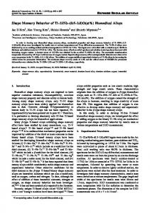
Fig. 1 Pseudo-elastic effect „T = Af…. „1… Elastic deformation of austenite; „2… austenite to single-variant martensite transformation „upper plateau…; „3… elastic deformation of single-variant martensite; „4… elastic strain recovery; „5… transformation strain recovery by unloading „lower plateau…. E = elastic modulus; h = transformation phase tangent modulus; ⑀L = maximum transformation strain; s0 = initial mean value of the mechanical hysteresis in the uniaxial tensile test; R = half of the mechanical hysteresis loop amplitude in the uniaxial tensile test; sAS = value of the stress deviatoric component inducing A \ S transformation.
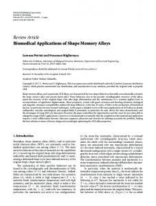
above A f at zero stress allows to recover the residual strain: indeed, the single-variant martensite is no more stable at this temperature and the inverse transformation 共S → A兲 takes place. The following cooling below M f lets the material go back to the multivariant martensite configuration 共A → M兲 but without any macroscopic deformation. This peculiar behavior is the so-called shape memory effect 共Fig. 2兲. Within the wide family of shape memory alloys, Ni–Ti associates shape memory and pseudo-elastic effects, characterized by
Fig. 2 Shape memory effect „T = Mf…. „1… Elastic deformation of multi-variant martensite; „2… multi-variant to single-variant martensite transformation; „3… elastic deformation of single-variant martensite; „4… elastic strain recovery; „5… transformation strain recovery by thermal loading. E = elastic modulus; h = transformation phase tangent modulus; ⑀L = maximum transformation strain; s0 = initial mean value of the mechanical hysteresis in the uniaxial tensile test; R = half of the mechanical hysteresis loop amplitude in the uniaxial tensile test; sMS = value of the stress deviatoric component inducing M \ S transformation; ⌬T = temperature increment above Af inducing inverse transformation.
Journal of Biomechanical Engineering
Fig. 3 Stress deviatoric component inducing transformationtemperature relation. sMS = value of the stress deviatoric component inducing M \ S transformation at temperature T Ï Mf; sAS = value of the stress deviatoric component inducing A \ S transformation at temperature T = Af.
large plateau and stress hysteresis, with good resistance to corrosion, biocompatibility and fatigue resistance 关9–11兴, magnetic resonance compatibility, kink resistance and dynamic interference 关12兴. These features explain why Ni–Ti alloys have rapidly become the material adopted for several implantable devices in the past ten years. Examples are blood flow filters, atrial septal occluser devices, self-expandable stents, spinal vertebrae spacers, orthopedic staples, plates for the recovery bones, surgical instruments such as baskets to remove kidney, bladder and bile duct stones, catheters, gripper, scissors and tongs for laparoscopic procedures 关13–26兴. The aim of these devices is to make interventional and endoscopic procedures as minimally invasive as possible exploiting Ni–Ti features. In this context, constitutive models able to describe SMA behavior and their implementation into finite element codes are becoming an important tool for designers and a requirement in Food and Drug Administration submissions. If nowadays scientific literature is very rich in numerical models able to describe with good accuracy the thermo-mechanical response of Ni–Ti 关27–37兴, the possibility of performing finite element analyses of SMA devices with commercial code is quite limited. Starting from these considerations, the authors 关38兴 developed a model able to catch the most significant SMA macroscopic features, without claiming to be complete and exhaustive in describing all the SMA peculiar properties: in particular, it accounts for the shape memory effect, the pseudo-elastic effect as well as the intermediate behaviors, the asymmetric response in tensioncompression test and the stress rate due to the thermo-mechanical coupling. Moreover, peculiar attention has been given to the algorithm development which results robust and efficient. The model is implemented into the commercial code ABAQUS 共ABAQUS Inc., Pawtucket, RI兲. After a short presentation of the model, this work is dedicated to showing the numerical algorithm ability to simulate medical devices exploiting SMA behavior. Accordingly, the comparison between experimental and numerical response of an intravascular coronary stent is used to verify the model suitability to describe pseudo-elasticity. The numerical study of a spinal vertebrae spacer, where the effects of different geometry and material characteristic temperatures have been investigated, is used to verify the model suitability to describe shape memory effect. AUGUST 2005, Vol. 127 / 717
Downloaded 14 Nov 2007 to 193.206.66.82. Redistribution subject to ASME license or copyright, see http://www.asme.org/terms/Terms_Use.cfm
Table 1 Model user subroutine input data E = Elastic modulus = Poisson’s coefficient ⑀L = Transformation strain h = Transformation phase tangent modulus  = Coefficient of the stress deviatoric component inducing transformation-temperature relation M f = Martensite finish transformation temperature T = Current temperature R = Half of the mechanical hysteresis loop amplitude in the uniaxial tension-compression case m = Coefficient related to the asymmetric behavior of SMA in tension and compression
Material and Method Numerical Model. A three-dimensional constitutive model 关38兴 has been developed within the framework of phenomenological continuum thermomechanics 关39兴. The strain, ⑀, and the absolute temperature, T, are assumed as control variables, while a traceless second-order transformation strain tensor etr is the internal variable. It means that at most the model may distinguish between a generic parent phase 共not associated with any macroscopic strain兲 and a generic product phase 共associated with a macroscopic strain兲. Moreover, indicating with ⑀L the maximum transformation strain reached at the end of the transformation during a uniaxial test, it is required 0 艋 储etr储 艋 ⑀L
共1兲
where ⑀L can be regarded as a material parameter. Assuming a small strain regime,1 the free energy function ⌿ for a polycrystalline SMA material is expressed through the following convex potential: 1 ⌿共⑀,e ,T兲 = K2 + G储e − etr储2 − 3␣K共T − T0兲 + 具T − M f 典储etr储 2 tr
1 + h储etr储2 + I⑀L共etr兲 2
共2兲
where and e are, respectively, the volumetric and the deviatoric components of the total strain, K the bulk modulus, G the shear modulus, ␣ the thermal expansion coefficient, T0 a reference temperature,  a material parameter related to the dependence of the 1 The use of the small deformation theory can be justified if one considers that in many biomedical applications large displacements but small strains are induced.
stress inducing transformation on the temperature and 具•典 the positive part of the argument, h a material parameter defining the slope of the linear stress-transformation strain relation in the uniaxial case and finally I⑀L共etr兲 is set equal to an indicator function introduced to satisfy the constraint on the transformation strain norm I⑀L共etr兲 =
再
0
if 储etr储 艋 ⑀L
+ ⬁ if 储etr储 ⬎ ⑀L
冎
共3兲
Following standard arguments, the constitutive equations are derived
冦
= K关 − 3␣共T − T0兲兴 s= = 2G共e − etr兲 e 具T − M f 典 =− = 3␣K − 储etr储 T 兩T − M f 兩 p=
X = − tr = s − ␣ e
冧
共4兲
where p and s are, respectively, the volumetric and the deviatoric part of the stress ; is the entropy; X is the thermodynamic force associated with the transformation strain and indicated in the following as transformation stress; ␣ plays a role similar to the backstress in classical plasticity and is defined by
␣ = 关具T − M f 典 + h储etr储 + ␥兴
储etr储 etr
共5兲
where the terms 具T − M f 典 and h储etr储 describe, respectively, a piecewise linear dependency of ␣ on the temperature and a linear
Fig. 4 Experimental instrumentation: thermostatic fluid circuit with the MTS SYNERGIE 200H electromechanical machine. A sketch of the circuit is shown.
718 / Vol. 127, AUGUST 2005
Transactions of the ASME
Downloaded 14 Nov 2007 to 193.206.66.82. Redistribution subject to ASME license or copyright, see http://www.asme.org/terms/Terms_Use.cfm
Fig. 5 CAD model of the Ni–Ti stent simulated
hardening behavior proportional to 储etr储 during the phase transformation; ␥ is the subdifferential of the indicator function 关40兴
再
␥ = 0 if 0 艋 储etr储 ⬍ ⑀L ␥ 艌 0 if 储etr储 = ⑀L
冎
共6兲
The model is completed introducing the associative evolution law for etr
F共X兲 e˙ tr = ˙
Fig. 6 Boundary conditions of the stent model: the highlighted points, belonging to the line tangent to the lower plane, are restrained to move along direction 1
共7兲
and the Kuhn–Tucker conditions
˙ 艌 0
F艋0
˙ F = 0
•
where ˙ plays a role similar to the plastic consistent parameter and F plays the role of a limit function. In particular a Prager–Lodetype limit surface 关41,42兴 has been assumed. Further details on the constitutive model and a discussion on the time discrete counterpart can be found in Ref. 38. The model parameter meaning can be more easily understood considering a uniaxial tensile test with 储X储 = 兩X兩 and 储etr储 = 兩etr兩 ⬍ ⑀L. In this case, the yield function becomes F共X兲 = 兩X兩 − R
共8兲
Hence, the stress deviatoric component is given by s = s0 + h兩etr兩 + R
共9兲
where the right terms of Eq. 共9兲 have the following meaning: •
s0 = 具T − M f 典 represents the initial 共etr = 0, etr ⫽ 0兲 mean value of the mechanical hysteresis 共Fig. 1兲. It varies linearly with the temperature, starting from 0 at T = M f 共Fig. 2兲. Accordingly, the value of the stress deviatoric component inducing transformation is s0 + R and depends linearly on the temperature. In particular, for the transformation A → S at
Table 2 Material parameters for stent and spacer „SMA1 and SMA2… models Values Properties
Stent
SMA1
SMA2
E ⑀L h  Mf T R m
75 000 MPa 0.3 7% 4000 MPa 7 MPa/ K 263 K 310 K 70 MPa 0
70 000 MPa 0.3 7% 500 MPa 8.3 MPa/ K 311 K 328 K 120 MPa 0
70 000 MPa 0.3 7% 500 MPa 8.3 MPa/ K 289 K 311 K 120 MPa 0
Journal of Biomechanical Engineering
temperature T = A f , it results in sAS = 共A f − M f 兲 + R; for the transformation M → S at temperature T 艋 M f it is s MS = R 共Fig. 3兲. h兩etr兩 describes linear hardening behavior proportional to 兩etr兩 during phase transformation.
Figures 1 and 2 show characteristic uniaxial tensile stress-strain curves of SMA at temperature A f 共pseudo-elasticity兲 and M f 共shape memory effect兲 respectively, as described by the model. The discretized model has been implemented through the UMAT user subroutine in ABAQUS code. Table 1 reports the material parameters to be defined into the user subroutine for the numerical analyses. Biomedical Applications. Two devices are selected to show the potentials of the model: a coronary stent and a spinal vertebrae spacer. The stent is chosen for two main reasons: 共i兲 it is one of the most diffused applications of pseudo-elastic Ni–Ti in the biomedical field; 共ii兲 the availability of some devices allows the authors to compare numerical results with experimental tests. Among the medical devices exploiting shape memory effect, the spinal vertebrae spacer is chosen for the growing interest for this type of product into the medical field. In the following a brief description of the two devices is outlined before addressing the finite element method 共FEM兲 study. Intravascular stents are expandable tube-like structures permanently placed into stenotic arteries to restore blood perfusion: they serve as a scaffold for the artery increasing the blood flow to the downstream vessels. Nowadays, different types of devices are available: stainless steel stent, Ni–Ti stent and polymer stents. The stainless steel stent is mounted on a catheter supporting a balloon and is positioned by inflating the balloon in the site of the blockage. When the balloon is deflated and retracted, the stent, plastically deformed, remains in place and maintains the artery open. The Ni–Ti stent, in austenitic phase at room temperature 共the A f temperature of the stent material is lower than room temperature兲, is mounted on a catheter and is compressed by a protective sheath: when the catheter reaches the site of the blockage, the sheath is retracted and the stent expands into the artery exploiting pseudoelastic effect. In this case, a more flexible delivery system affords lower risk to overstretch the artery during expansion and lower bending stresses when deployed in tortuous vessels. However, the self-expandibility, which avoids the stainless steel stent characteristic radial dimension reduction immediately following the balAUGUST 2005, Vol. 127 / 719
Downloaded 14 Nov 2007 to 193.206.66.82. Redistribution subject to ASME license or copyright, see http://www.asme.org/terms/Terms_Use.cfm
Fig. 7 Three-dimensional CAD model of the spinal vertebrae spacer. Due to the symmetry only one fourth of the device is simulated. The mesh of the spacer and the boundary conditions are reported in the lower panel.
loon deflation, cannot be indicated as the only reason for the differences in generated neointima noticed between slotted-tube stainless steel and Ni–Ti stents 关43兴. Indeed, also the material, the strut geometry and cell geometry influence the restenosis rate. Regarding the polymer stents, they can be either balloon- and self-expandable 关44–46兴 and can be classified in resorbable and non-resorbable stents. The intervertebral disk has several important functions, including functioning as a spacer, as a shock absorber and as a motion unit: it maintains the separation distance between adjacent vertebral bodies allowing spine large motion in several directions as well as avoiding nerve compression; it allows the spine to com-
press and rebound during activities as jumping and running and it resists the downward pull of gravity on the head and trunk during prolonged sitting and standing; last, it allows the spinal segment to flex, rotate, and bend on the side. A spinal vertebrae spacer is a device that should be able to substitute for a damaged intervertebral disk. Accordingly, metals such as stainless steel and titanium, characterized by high stiffness, if compared with biological materials, and low damping are not suitable to realize spacers. The higher compliance and the ability of damping of Ni–Ti alloy coupled with the possibility of reducing the device dimension, crimping it during implantation and then recovering the original shape through shape memory effect, indicates SMA as the best choice for manufacturing effective spinal vertebrae spacers.
Table 3 Main geometrical dimensions „Fig. 7… for the three spacers studied
SMA Coronary Stent. The model ability to describe SMA devices exploiting pseudo-elasticity is verified comparing experimental and numerical results of a crush test on a Ni–Ti new generation coronary stent: the test consists in compressing the stent between two planes parallel to the stent longitudinal axis and is usually performed to evaluate the compliance of the device. The experimental instrumentation includes a MTS SYNERGIE 200H electromechanical machine 共100 N兲 for compression test under displacement control and a thermostatic fluid circuit to control the temperature in the test chamber 共Fig. 4兲. The crush test is performed as follows 共inset of Fig. 4兲. The planes, made of polyethylene, are positioned at an initial distance of 4.25 mm 共equal to
Geometricaldimension共mm兲 r L d D a b c e f
Model A 7.0 5.6 14.0 16.0 3.0 4.0 7.0 5.6 3.8
720 / Vol. 127, AUGUST 2005
Model B 6.2 5.6 12.4 16.0 2.2 3.5 7.0 5.0 2.5
Model C 6.2 5.6 12.4 16.0 2.4 3.5 7.0 5.0 3.2
Transactions of the ASME
Downloaded 14 Nov 2007 to 193.206.66.82. Redistribution subject to ASME license or copyright, see http://www.asme.org/terms/Terms_Use.cfm
Fig. 8 Results from the sensitivity analysis of the spacer model A: comparison between the displacement histories of a central node „upper panel… and the Von Mises stresses at the end of the loading path „lower panel… of three different meshes with 1530, 3336, and 5702 elements, respectively
the stent nominal diameter value in the expanded configuration兲 and the temperature is settled at 37° C 共body temperature兲; then the upper plane is moved with a velocity of 1 mm/ min crushing the stent till the 70% reduction of the diameter is reached. The plane is then moved back with the same velocity up to the initial unloaded configuration. In order to obtain more reliable results, three tests are carried out. A 3D computer aided design 共CAD兲 model of a coronary stent resembling the tested Ni–Ti device is developed 共Fig. 5兲 on the basis of measurements obtained at the optical microscope. The
Fig. 9 Comparison between experimental results from the crush test and computational curve by the FEM analysis
Journal of Biomechanical Engineering
thickness of the stent is 0.1 mm and the external diameter in the expanded configuration is 4.25 mm. The length of the stent is 5.24 mm. The CAD model is similar to that adopted in a previous study of ours 关47兴. The model is discretized 共inset of Fig. 5兲 by means of 29 263 10-node tetrahedral elements with a corresponding number of nodes of 64 046. The material mechanical characteristics of the tested stent are not available, hence average values derived from the literature are chosen for the Ni–Ti algorithm parameters 共Table 2兲. Two analytical surfaces are considered to simulate the polyethylene parallel flat planes: these planes are supposed to be infinitely rigid compared with the stent structure. The boundary conditions are chosen to avoid the stent sliding between the two planes as well as to allow the stent deformation during crushing: accordingly, some points belonging to the line tangent to the lower plane are restrained to move along direction 1 共Fig. 6兲. In the numerical analysis a displacement control is assumed and a dynamic simulation with an implicit formulation is used to provide integration of the stress/displacement response of the device. Indeed, this approach assures a major stability of the solution of the strongly non-linear problem under study. For this reason, a fictitious value of 0.0001 kg/ mm3 is specified for the material density. Moreover, a large deformation option is set to take into account non-linear geometry. The contact between analytical surfaces and stent is treated with an exponential pressure overclosure law with a friction coefficient of 0.05. Spinal Vertebrae Spacer. The model is used to compare the response of different Ni–Ti spinal spacers during implant and physiological loading history. The device is compressed in martensitic phase, assuming a reduced shape which helps the insertion AUGUST 2005, Vol. 127 / 721
Downloaded 14 Nov 2007 to 193.206.66.82. Redistribution subject to ASME license or copyright, see http://www.asme.org/terms/Terms_Use.cfm
Fig. 10 Numerical simulation: deformed „black… and undeformed „blue… configuration in a prospective view at the end of the loading step. In the lower panel the Von Mises stresses are depicted at the end of the loading step.
between the vertebrae. Once positioned into the body, it recovers its original expanded shape by residual deformation thermal recovery 共shape memory effect兲 and starts to work opposing force to spinal compressive load. Spacers different in material and geometry are considered to compare different possible design solutions. In particular, two Ni–Ti alloys 共SMA1 and SMA2兲, characterized by the material parameters summarized in Table 2, are investigated. Using SMA1, which has M f at body temperature 共M f = 311 K兲, the spacer is compressed and implanted when in martensitic phase and hence it is heated up to Tmax ⬎ A f = 325 K to recover the original shape into the body. Using SMA2, which has M f lower than room temperature 共M f = 289 K兲, the spacer is initially cooled up to Tmin ⬍ M f to perform compression and implantation in martensitic phase and hence it returns to the body temperature 共Tbody ⬎ A f 兲 recovering the original shape. The geometry of the spacer 共Fig. 7兲 is chosen referring to pictures as reported by Ref. 关1兴 and three different models 共A, B, and C兲 are compared with some different dimensions in thickness and holes 共as reported in Table 3兲. The models are discretized by means of ten-node tetrahedral elements: the number of elements is 3336, 3163, and 3313 and the number of nodes is 6233, 5653, and 5917, for model A, B, and C, respectively. These values are suggested by the sensitivity analysis performed for each device varying the number of elements between 722 / Vol. 127, AUGUST 2005
about 1500 and 6000. The results of this analysis for the model A are depicted in Fig. 8 which compares the results in terms of Von Mises stresses at the end of the loading path and in terms of displacement histories of a central node for three different meshes with 1530, 3336, and 5702 elements 共3192, 6233, and 10405 nodes兲, respectively. Boundary conditions are chosen in order to replace symmetry conditions on the planes 2–3 and 1–3 共Fig. 7兲: only one fourth of the device in the circumferential direction is studied. Moreover, one of the nodes belonging to the symmetry plane is constrained in direction 3 to avoid rigid body motion, allowing structure transversal deformation. An analytical rigid surface moving against the spacer is considered to simulate both the device compression performed before the implantation and the following compressive action of the adjacent vertebral bodies. Simulation of implantation and physiological loading history consists of the following steps: 1. starting from T = 297 K 共room temperature兲, the temperature remains constant in the case of the SMA1 model, while it is cooled up to Tmin = 285 K in the case of the SMA2 model: in both cases the spacer material is in martensitic phase; 2. the analytical rigid surface, positioned above the spacer, is moved down to compress the device 共displacement control兲; 3. the surface initial condition is replaced and the spacer recovTransactions of the ASME
Downloaded 14 Nov 2007 to 193.206.66.82. Redistribution subject to ASME license or copyright, see http://www.asme.org/terms/Terms_Use.cfm
Fig. 11 SMA1 Spacer A: central node vertical displacement in mm at different steps and some deformed configurations „black color in the inset…. The corresponding Von Mises contour maps of the deformed configurations are reported as well.
ers its elastic strains, while residual deformations are still present; 4. thanks to thermal load 共for SMA1 from T = 297 K to T = 328 K and for SMA2 from T = 285 K to T = 311 K兲, the conversion from single-variant martensite to austenite takes place and hence the residual strains are recovered, too;
5. temperature is settled on T = Tbody = 311 K for the SMA1 spacer, while it remains constant for the SMA2 device; 6. the surface is moved in contact with the spacer 共displacement control兲; 7. the surface is loaded with a physiological force of 1500 N 关48兴; and
Fig. 12 SMA2 Spacer A, B, and C: central node vertical displacement in mm at different steps
Journal of Biomechanical Engineering
AUGUST 2005, Vol. 127 / 723
Downloaded 14 Nov 2007 to 193.206.66.82. Redistribution subject to ASME license or copyright, see http://www.asme.org/terms/Terms_Use.cfm
8. the surface is unloaded up to physiological force of 600 N, simulating variation in compressive spinal force. ABAQUS/Standard with implicit formulation and large deformation option is used to provide the non-linear force/displacement response of the device. The contact between the analytical surface and the spacer is treated as in the previous case.
Results and Discussion SMA Intravascular Stent. Figure 9 depicts the loaddisplacement curves for the experimental and computational crush tests. Because it was impossibile to perform experimental tests on the sole stent material as it was not available, and hence to fit the continuum mechanical model to these data, the obtained results cannot be used as a validation of the material constitutive model and they cannot be assumed as representative of the real stent behavior. For this reason a sensitivity analysis, which should be performed, has been avoided and can be included in the limitations of this work. However, the observed agreement between numerical and experimental curves is an encouraging result suggesting that once the exact knowledge of the real characteristic material parameters is achieved, numerical models, as the one here proposed, can be used to simulate the strongly non-linear behavior of the shape memory alloy stent. As regards to the computational results, the deformed and the undeformed configurations and Von Mises stresses at the end of loading step are reported in Fig. 10. These results show the implemented model capability to describe a fully three-dimensional behavior of SMA devices as well as the useful ABAQUS option to plot all the interesting stress and strain quantities, even for user routines. On the other hand, they are functional to understand the device response in terms of stress and strain distribution and hence they give interesting information for designing optimization. Proper changes in some stent features could produce a design where strain is well distributed throughout the stent and hence a large percentage of material exploits pseudo-elasticity with very low risk of overcoming maximum recoverable strain limit and with high deformation recovery. At the same time, the stent compliance could be optimized to make the stent able to resist the occlusion force of the artery and to maintain the artery open without excessive stretching. Spinal Vertebrae Spacer. This second example aims to show the model capability to describe shape-memory effect, as well as the potentials of the implemented routine in the device design. Figure 11 summarizes the device 共material type SMA1, model A兲 response in terms of displacement history of a central node of the model during crimping, thermal shape recovery and physiological loading steps. For the most significant steps, deformed versus undeformed shapes are also reported 共insets of Fig. 11兲. Figure 12 compares the responses obtained for the spacer changing geometry data 共models A, B, and C兲 in the case of material-type SMA2. In particular, the performed simulations highlight the excessive flexibility of spacer A, unable to support the physiological force, versus the good and quite similar performance of spacers B and C. Moreover, a lack of differences between SMA1 and SMA2 spacers is detected from the mechanical point of view. The preferred choice depends on the working condition and on the physiological temperature range. Finally, the implemented routine allows to catch the temperature dependence of the spacer response and to identify the zones where the transformation takes place and eventually to optimize the device shape. Indeed, the shape-memory effect is maximized as much as the transformation is diffused without overcoming the limit 储etr储 ⬍ ⑀L. A limitation of these models is the absence of the surrounding tissues and the connecting screws. Indeed, when implanted, a spacer is connected to the adjacent vertebrae with screws. This certainly influences the deformation behavior of the spacer under 724 / Vol. 127, AUGUST 2005
load. However, our aim is to investigate numerically the possibility of utilizing the shape memory effect for a spinal spacer as could be done in an in vitro test performed in the laboratory. This is an important step in the design and optimization of the device and before prototyping and experimental phases.
Conclusions The present study shows the potentials of the proposed model to study the performance of SMA biomedical devices exploiting both pseudo-elastic effect and shape memory effect by means of finite element commercial codes. One of the main limits of shape memory alloys is the strong dependency of the material properties from the chemical composition and thermo-mechanical treatment: even if the lack of this information makes the quantitative indications given by numerical analyses of existing SMA products not completely reliable, the results herein presented show the importance of computational studies in designing and optimizing new devices.
Acknowledgment Support from the MIUR 共Ministero dell’Istruzione, dell’Università e della Ricerca, Italian Ministry of Education, University and Research兲 through Grant COFIN 2002.
References 关1兴 Duerig, T. W., Melton, K. N., Stökel, D., and Wayman, C. M., Eds., 1990, Engineering Aspects of Shape Memory Alloys, Butterworth-Heinemann, London. 关2兴 Pelton, A. R., Hodgson, D., and Duerig, T., Eds., 1995, Proc. of First Int. Conf. on Shape Memory and Superelastic Technologies, Asilomar, CA. 关3兴 Pelton, A. R., Hodgson, D., and Duerig, T., Eds., 1997, Proc. of Second Int. Conf. on Shape Memory and Superelastic Technologies, Asilomar, CA. 关4兴 Barras, C. D. J., and Myers, K. A., 2000, “Nitinol—Its Use in Vascular Surgery and Other Applications,” Eur. J. Vasc. Endovasc Surg., 19, pp. 564–569. 关5兴 Russel, S. M., and Pelton, A. R., Eds., 2000, Proc. of Third Int. Conf. on Shape Memory and Superelastic Technologies, Asilomar, CA. 关6兴 Funakubo, H., 1987, Shape Memory Alloys, Gordon and Breach, New York. 关7兴 Otsuka, K., and Wayman, C. M., 1998, Shape Memory Materials, Cambridge University Press, Cambridge. 关8兴 Wayman, C. M., 1992, “Shape Memory and Related Phenomena,” Prog. Mater. Sci., 36, pp. 203–224. 关9兴 Trepanie, C., Leung, T. K., Tabrizian, M., Yahia, L. H., Bienvenu, J. G., Tanguay, J. F., Piron, D. L., and Bilodeau, L., 1999, “Preliminary Investigation of the Effects of Surface Treatments on Biological Response to Shape Memory NiTi Stents,” J. Biomed. Mater. Res., 48, pp. 165–171. 关10兴 Thierry, B., Merhi, Y., Bilodeau, L., Trepanier, C., and Tabrizian, M., 2002, “Nitinol Versus Stainless Steel Stents: Acute Thrombogenicity Study in an Ex Vivo Porcine Model,” Biomaterials, 23, pp. 2997–3005. 关11兴 Ryhnen, J., 1995, “Biocompatibility Evaluation of Nickel-Titanium Shape Memory Metal Alloy,” PhD Dissertation, Oulu University. 关12兴 Duerig, T. W., Pelton, A. R., and Stckel, D., 1997, “Superelastic Nitinol for Medical Devices,” Medical Plastics Biomater., 2, pp. 30–43. 关13兴 Bruckheimer, E., Judelman, A. G., Bruckheimer, S. D., Tavori, I., Naor, G., and Katzen, B. T., 2003, “In Vitro Evaluation of a Retrievable Low-Profile Nitinol Vena Cava Filter,” J. Vasc. Interv. Radiol., 14, pp. 469–474. 关14兴 Leask, R. L., Johnston, K. W., and Ojha, M., 2001, “In Vitro Hemodynamic Evaluation of a Simon Nitinol Vena Cava Filter: Possible Explanation of IVC Occlusion,” J. Vasc. Interv. Radiol., 12, pp. 613–618. 关15兴 Simon, M., Rabkin, D. J., Kleshinski, S., Kim, D., and Ransil, B. J., 1993, “Comparative Evaluation of Clinically Available Inferior Vena Cava Filters with an In Vitro Physiologic Simulation of the Vena Cava,” Radiology, 189, pp. 769–774. 关16兴 Kong, H., Gu, X., Titus, J. L., Kim, T. H., Urness, M., Han, Y. M., Hessliein, P., Bass, J., Chun, M., and Hunter, D. W., 2002, “Creation of an Intra-Atrial Communication with a New Amplatzer Shunt Prosthesis: Preliminary Results in a Swine Model,” Catheter. Cardiovasc. Interv., 56, pp. 267–271. 关17兴 Walsh, K. P., and Maadi, I. M., 2000, “The Amplatzer Septal Occluder,” Cardiol. Young 10共5兲, pp. 493–501. 关18兴 Smits, M., Huibregtse, K., and Tytgat, G., 1995, “Results of the New Nitinol Self-Expandable Stents for Distal Biliary Structures,” Endoscopy, 27, pp. 505–508. 关19兴 Tyagi, S., Singh, S., Mukhopadhyay, S., and Kaul, U. A., 2003, “Self- and Balloon-Expandable Stent Implantation for Severe Native Coarctation of Aorta in Adults,” Am. Heart J., 146, pp. 920–928. 关20兴 Dai, K. R., Hou, X. K., Sun, Y. H., Tang, R. G., Qiu, S. J., and Ni, C., 1993, “Treatment of Intra-Articular Fractures with Shape Memory Compression Staples,” Injury, 24, pp. 651–655. 关21兴 Sanders, J. O., Sanders, A. E., More, R., and Ashman, R. B., 1993, “A Preliminary Investigation of Shape Memory Alloys in the Surgical Correction of
Transactions of the ASME
Downloaded 14 Nov 2007 to 193.206.66.82. Redistribution subject to ASME license or copyright, see http://www.asme.org/terms/Terms_Use.cfm
Scoliosis,” Spine, 18, pp. 1640–1646. 关22兴 Wever, D. J., Elstrodt, J. A., Veldhuizen, A. G., and v Horn, J. R., 2002, “Scoliosis Correction with Shape Memory Metal: Results of an Experimental Study,” Eur. Spine J., 11, pp. 100–106. 关23兴 Ryhanen, J., Niemela, E., Kaarela, O., and Raatikainen, T., 2003, “Stabilization of Acute, Complete Acromioclavicular Joint Dislocations with a New C Hook Implant,” J. Shoulder Elbow Surg., 12, pp. 442–445. 关24兴 Kourambas, J., Del vecchio, F. C., Munver, R., and Preminger, G. M., 2000, “Nitinol Stone Retrieval-Assisted Ureteroscopic Management of Lower Pole Renal Calculi,” Urology, 56, pp. 935–939. 关25兴 Song, H. Y., Shin, J. H., Lim, J. O., Kim, T. H., Lee, G. H., and Lee, S. K., 2004, “Use of a Newly Designed Multifunctional Coil Catheter for Stent Placement in the Upper Gastrointestinal Tract,” J. Vasc. Interv. Radiol., 15, pp. 369–373. 关26兴 Sundaram, C. P., Ono, Y., Landman, J., Rehman, J., and Clayman, R. V., 2002, “Hydrophilic Guide Wire Technique to Facilitate Organ Entrapment Using a Laparoscopic Sack During Laparoscopy,” J. Urol. 共Baltimore兲, 167, pp. 1376– 1377. 关27兴 Auricchio, F., Taylor, R. L., and Lubliner, J., 1997, “Shape-Memory Alloys: Macromodelling and Numerical Simulations of the Superelastic Behavior,” Comput. Methods Appl. Mech. Eng., 146, pp. 281–312. 关28兴 Peyroux, R., Chrysochoos, A., Licht, C., and Lobel, M., 1998, “Thermomechanical Couplings and Pseudoelasticity of Shape Memory Alloys,” Int. J. Eng. Sci., 36, pp. 489–509. 关29兴 Souza, A. C., Mamiya, E. N., and Zouain, N., 1998, “Three-Dimensional Model for Solids Undergoing Stress-Induced Phase Transformations,” Eur. J. Mech. A/Solids, 17, pp. 789–806. 关30兴 Idesman, A. V., Levitas, V. I., and Stein, E., 1999, “Elastoplastic Materials with Martensitic Phase Transition and Twinning at Finite Strain: Numerical Solution with the Finite Element Method,” Comput. Methods Appl. Mech. Eng., 173, pp. 71–98. 关31兴 Qidwai, M. A., and Lagoudas, D. C., 2000, “Numerical Implementation of a Shape Memory Alloy Thermomechanical Constitutive Model Using Return Mapping Algorithms,” Int. J. Numer. Methods Eng., 47, pp. 1123–1168. 关32兴 Qidwai, M. A., and Lagoudas, D. C., 2000, “On Thermomechanics and Transformation Surfaces of Polycristalline NiTi Shape Memory Alloy Material,” Int. J. Plast., 16, pp. 1309–1343. 关33兴 Auricchio, F., and Sacco, E., 2001, “Thermo-Mechanical Modelling of a Superelastic Shape-Memory Wire under Cyclic Stretching-Bending Loadings,” Int. J. Solids Struct., 38, pp. 6123–6145. 关34兴 Govindjee, S., and Miehe, C., 2001, “A Multi-Variant Martensitic Phase Transformation Model: Formulation and Numerical Implementation,” Comput.
Journal of Biomechanical Engineering
Methods Appl. Mech. Eng., 191, pp. 215–238. 关35兴 Peng, X., Yang, Y., and Huang, S., 2001, “A Comprehensive Description for Shape Memory Alloys with a Two-Phase Constitutive Model,” Int. J. Solids Struct., 38, pp. 6925–6940. 关36兴 Ziolkowski, A., 2001, “Finite Element Modelling of SMA Structures,” Workshop on Shape Memory Alloy Materials-Warsaw, 3–6 September, pp. 1–33. 关37兴 Liew, K. M., Kitipornachai, S., Ng, T. Y., and Zou, G. P., 2002, “MultiDimensional Superelastic Behavior of Shape Memory Alloys Via Nonlinear Finite Element Method,” Eng. Struct., 24, pp. 51–57. 关38兴 Auricchio, F., and Petrini, L., 2004, “A Three-Dimensional Model Describing Stress-Temperature Induced Solid Phase Transformations: Solution Algorithm and Boundary Value Problems,” Int. J. Numer. Methods Eng., 61, pp. 807– 836. 关39兴 Lubliner, J., 1990, Plasticity Theory, Macmillan, New York. 关40兴 Fremond, M., 1996, CISM Courses and Lectures: Shape Memory Alloys 共Springer, Wien, New York兲 351, pp. 1–68. 关41兴 Patoor, E., Eberhardt, A., and Berveiller, M., 1996, “Micromechanical Modelling of Superelasticity in Shape Memory Alloys,” J. Phys. IV, C1–6, pp. 277–292. 关42兴 Manach, P. Y., and Favier, D., 1997, “Shear and Tensile Thermomechanical Behavior of Equiatomic NiTi Alloy,” Mater. Sci. Eng., A, 222, pp. 45–57. 关43兴 Carter, A. J., Scott, D., Laird, J. R., Bailey, L., Kovach, J. A., Hoopes, T. G., Pierce, K., Heath, K., Hess, K., Farb, A., and Virmani, R., 1998, “Progressive Vascular Remodeling and Reduced Neointimal Formation after Placement of a Thermoelastic Self-Expanding Nitinol Stent in an Experimental Model,” Cathet. Cardiovasc. Diagn., 44, pp. 193–201. 关44兴 Tamai, H., Igaki, K., Kyo, E., Kosuga, K., Kawashima, A., Matsui, S., Komori, H., Tsuji, T., Motohara, S., and Uehata, H., 2000, “Initial and 6-Month Results of Biodegradable Poly-l-lactic Acid Coronary Stents in Humans,” Circulation, 102, pp. 399–404. 关45兴 Lendlein, A., and Langer, R., 2002, “Biodegradable, Elastic Shape-Memory Polymers for Potential Biomedical Applications,” Science, 296, pp. 1673– 1676. 关46兴 Wache, H. M., Tartakowska, D. J., Hentrich, A., and Wagner, M. H., 2003, “Development of a Polymer Stent with Shape Memory Effect as a Drug Delivery System,” J. Mater. Sci.: Mater. Med., 14, pp. 109–112. 关47兴 Migliavacca, F., Petrini, L., Massarotti, M., Schievano, S., Dubini, G., and Auricchio, F., 2004, “Stainless and Shape Memory Alloy Coronary Stents: A Computational Study on the Interaction with the Vascular Wall,” Biomech. Model. Mechanobiol., 2共4兲, pp. 205–217. 关48兴 Nachemson, A., 1966, “The Load on Lumbar Disks in Different Positions of the Body,” Clin. Orthop. Relat. Res., 45, pp. 107–122.
AUGUST 2005, Vol. 127 / 725
Downloaded 14 Nov 2007 to 193.206.66.82. Redistribution subject to ASME license or copyright, see http://www.asme.org/terms/Terms_Use.cfm