I.J. Modern Education and Computer Science, 2016, 12, 31-37 Published Online December 2016 in MECS (http://www.mecs-press.org/) DOI: 10.5815/ijmecs.2016.12.05
Computer Modeling and Simulations of Logic Circuits Gergana Kalpachka South-West University „Neofit Rilski“, Blagoevgrad, 2700, Republic of Bulgaria Email:
[email protected]
Abstract—In thе article are presented possibilities of computer modeling and simulations of logic circuits using the software CircuitMaker. CirciutMaker is one of the widely used software product for quick and easy synthesis and simulating the work of the various electronic circuits. By using CirciutMaker are created logical elements and synthesized logic circuits such as decoders, multiplexers, counters, programmable logic device, etc., that allow conducting computer simulations and experiments to solve specific experimental tasks. The work of the shown circuits is illustrated with the timeimpulse diagrams. The application of the software product CirciutMaker for students who study the course „Analysis and synthesis of logic circuits“ is also considered. The computer modeling and the simulations of logic circuits can be used in the lectures and in the laboratory exercises on the course „Analysis and synthesis of logic circuits“ to conduct computer (virtual) interactive experiments. Index Terms—Computer Modeling, Computer Simulations, CircuitMaker, Logic Circuits, Analysis and Synthesis of Logic Circuits. I. INTRODUCTION Continuous development and improvement of the computer systems and the application software allows their use in to solve various tasks and problems of activity and life of contemporary person. Computer modeling is mathematical modeling, which uses computer tools to create models and to conduct computer (virtual) interactive experiments with them. Computer equipment and software (universal and specialized) are the most important parts of computer modeling. Different computer configurations and software products are created for use in certain areas – science, technique, education, healthcare, manufacturing and others. In the area of computer modeling of analog, digital and analog-digital circuits there is a huge variety of interactive environments, enabling synthesis, simulating and testing various modules, blocks, devices and others. This facilitates the synthesis of new electronic circuits. Interactive environments with such applications are: CircuitMaker, OrCAD PSpice, CADSTAR, LabVIEW,
Copyright © 2016 MECS
AutoCAD, Electronics Workbench MultiSim, Protel, Logisim, Logic Circuit, etc. The actuality of this article is determined by global trends in the development of: the automation of circuit design; the computer modeling of various electronic circuits; the computer simulations and optimization of projects; the computer processing and visualization of results. In this article are presented possibilities of computer modeling and simulations of logic circuits using the software product CircuitMaker. The application of this software for students who study the course „Analysis and synthesis of logic circuits“ is also considered in the article. In section II of the article is presented briefly the software product Circuit Maker. Main possibilities for its use in the computer modeling and simulations of logic circuits are described. In this section are presented created logic elements and synthesized logic circuits such as decoders, multiplexers, counters and other using CirciutMaker. In section III of the article are presented application possibilities of the software product CircuitMaker in teaching on the course „Analysis and synthesis of logic circuits“. The software product CircuitMaker can be used in the lectures and in the laboratory exercises for computer modeling and simulations of logic elements and circuits. In section IV of article the main conclusions that are formulated are presented. The references on the subject of the article are presented in section V. The used literature is in English and in Cyrillic.
II. COMPUTER MODELING AND SIMULATIONS OF LOGIC CIRCUITS USING THE SOFTWARE PRODUCT CIRCUITMAKER CirciutMaker is one of the most used software for synthesis and simulating of analog, digital and analogdigital circuits. CirciutMaker provides opportunities for quick and easy design of electronic circuits, testing their work and visualizing and tracking the signals from inputs to outputs of circuits, etc. [1]; [2]; [3].
I.J. Modern Education and Computer Science, 2016, 12, 31-37
32
Computer Modeling and Simulations of Logic Circuits
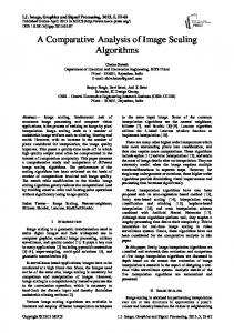
The software product CircuitMaker supports two modes of simulations – analog and digital. The software product CircuitMaker allows simulations when analog and digital elements are included in one circuit. In computer modeling and simulations of logic circuits CircuitMaker can be used for: synthesis of logic circuits by using finished elements included in program item „Library“ or by synthesis the necessary logic elements and their inclusion in the „User library“; study of the work of logic elements and circuits by conducting computer simulations; observation of internal transition states and processes; computer processing and presentation of the results (for example, by time-impulse diagrams, etc.), derived from computer experiments. CirciutMaker supports an extensive library of analog and digital elements which are necessary for the synthesis of various electronic circuits. It also supports finished exemplary circuits of certain electronic devices such as counters, security alarms, optocouplers, etc. The available items are organized into groups by name or purpose (Fig. 1). CirciutMaker enables creation of new elements and adding them into libraries with other elements. Creating a new element involves the following stages: synthesis of its circuit (Fig. 2), simulating of his work, creating a character by which the element is named in the program (Fig. 3). Adding an item to the libraries is accomplished by saving it as a macro with a name and choosing the category in which to be involved.
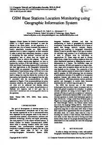
On Fig. 2 is shown a synthesized logic circuit of a decoder with four inputs and seven outputs (de 7447, Fig. 3). Its outputs are connected to the seven-segment indicator, and on its inputs the signals are from the outputs of the binary counters for example [4]; [5]; [6]; [7]; [8]; [9]. On Fig. 3 are shown some of the additional logic elements created as macros: multiplexers 2:1 and 4:1, decoder with three inputs and eight outputs, decoder with four inputs and seven outputs. For conducting computer simulations of logic circuits in the software product CircuitMaker is used digital simulations mode, because it aims measuring and researching of digital parameters. In digital simulation mode important are only the logical levels of the signals in the logic circuits. The digital simulations mode offers a variety of options: running the simulations step by step with options for determining the size of the step; visualizing the signal levels by connecting LEDs or oscilloscopes to certain points; visualizing the changes in the signals at different points of the circuits by time-impulse diagrams, etc. Integrated circuits and logic elements do not have pins for supply voltage and grounding, so that their unrelated to them does not prevent the conduct of simulations. While conducting computer simulations of logic circuits activities are summarized as follows: set the values of the input signals (variables); conducting a series of simulations to achieve the objectives;
Fig.1. Screen of CirciutMaker (Device Selection).
Copyright © 2016 MECS
I.J. Modern Education and Computer Science, 2016, 12, 31-37
Computer Modeling and Simulations of Logic Circuits
observation of internal transition states and processes; analyzing the information displayed on the screen during the simulations and then in the form of a time-impulse diagram at one point, as high or low
33
logic level signals at inputs and outputs of a logic element or circuit, etc.; recording of the obtained results; analysis and interpretation of the results and formulating conclusions.
Fig.2. A logic circuit of a decoder with four inputs and seven outputs.
Fig.3. Logic elements created as macros.
Copyright © 2016 MECS
I.J. Modern Education and Computer Science, 2016, 12, 31-37
34
Computer Modeling and Simulations of Logic Circuits
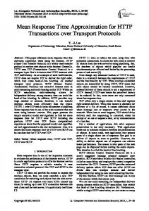
As a result of the actual application of the software product CircuitMaker are synthesized various logic circuits that allow conducting computer simulations and experiments to solve specific tasks. Logic elements, electronic devices from the library of CircuitMaker and macros created as additional elements are used for these purposes. The software product CircuitMaker allows storage of synthesized logic circuits and, if necessary, their structure can be edited. On Fig. 4 is shown a logic circuit of a reversible binary trigger counter of impulses with random coefficient of division and its simulation in a random moment of time. In this case the counter operates as a adder with coefficient of division D = 7. On the time-impulse diagram are shown input and output signals of the counter (Fig. 4). The wires which are colored in red are with high logic level signal, while the others wires colored in blue are with low logic level signal. On Fig. 5 is shown a logic circuit of a decoder with three inputs and eight outputs. This decoder is synthesized with logical NOR elements. The input and output signals of the decoder are shown on the timeimpulse diagram (Fig. 5).
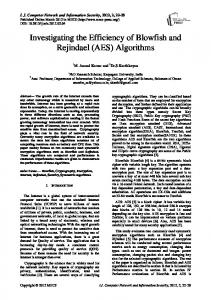
On Fig. 6 is shown a logic circuit of a programmable logic device and its simulation in a random moment of time. The synthesized programmable logic device includes AND-matrix and OR-matrix. With it can be realized logic circuits of systems with three logical functions of three variables. Opportunities offered by the software product CircuitMaker for computer modeling and simulations of logic circuits, significantly reduce the time for synthesis and study of their work.
III. APPLICATION OF THE SOFTWARE PRODUCT CIRCUITMAKER IN THE THEACHING ‘ANALYSIS AND SYNTHESIS OF LOGIC CIRCUITS’ The specific aspects of the education (content, teaching methods, used teaching aids and others.) directly dependent on the achievements of science, technique and technologies. In the teaching of students in technical specialties are increasingly used software products for synthesis, simulating and testing of analog, digital and analogdigital circuits, etc. [1]; [2]; [10]; [11]; [12]; [13]; [14]; [15]; [16].
Fig.4. A logic circuit of a reversible binary trigger counter with random coefficient of division.
Copyright © 2016 MECS
I.J. Modern Education and Computer Science, 2016, 12, 31-37
Computer Modeling and Simulations of Logic Circuits
35
Fig.5. A logic circuit of a decoder with three inputs and eight outputs.
Computer modeling and simulations of logic circuits through the software product CircuitMaker can be used in the lectures and in the laboratory exercises on the course „Analysis and synthesis of logic circuits“. In the lecture course of „Analysis and synthesis of logic circuits“ already synthesized logic circuits can be used to: illustration of educational content by conducting computer demonstration experiments (quantitative and qualitative); improving the accessibility of the statement of lectures on the course; creating of problematic situations and solve technical problems and tasks; introducing new concepts, values, etc.; researching and establishment of functional dependencies and disclosure of causal relationships; analyzing of specific situations; formulating laws, regularities and conclusions; facilitate the transition from the concrete to the abstract and back; constructing logical and creative style of thinking among students; creating cognitive interest, etc. Copyright © 2016 MECS
After students learned the opportunities of the software product CircuitMaker, they can synthesize logic elements and circuits and they can study their work in the laboratory exercises by conducting computer simulations and experiments. The shown logic elements and circuits on Fig. 2–6 can be used in the lectures and in the laboratory exercises in teaching on the course „Analysis and synthesis of logic circuits“. While conducting computer interactive experiments and exercises students see in practice applications of computers and computer technologies. They learn some of the contemporary methods and tools used in science and technique for synthesis, researching and studying of logic circuits and processing and presentation of the obtained results.
IV. CONCLUSION The computer modeling is an effective method of scientific knowledge for research the work of logic circuits. The opportunities that software products on the type of CircuitMaker offer in terms of synthesis, simulations and studying of logic circuits are widely used in science, technique, education and others.
I.J. Modern Education and Computer Science, 2016, 12, 31-37
36
Computer Modeling and Simulations of Logic Circuits
Fig.6. A logic circuit of a programmable logic device.
Computer modeling and simulations of logic circuits can be used and conducted in order to obtain results, which in real terms is need suitable material and technical basis or specific equipment. One of the modern and actual applications of computer modeling and simulations of logic circuits is in the education of students from the technical specialties at the universities. Computer modeling and simulations of logic circuits can be used in the lectures and in the laboratory exercises in the teaching on the course „Analysis and synthesis of logic circuits“. The computer modeling and simulations of logic circuits with different software producs can be used also for distance learning students. The software product CircuitMaker can be used for computer modeling and simulations not only to the logic circuits, but also to electronic circuits with different functional designation. REFERENCES [1] V. Milovanski and G. Kalpachka, „Numerical Modeling and Computer Simulations of Voltage Resonance“, Научно-теоретический журнал „Вестник современной науки“, № 4, pp. 34–38, 2015.
Copyright © 2016 MECS
[2] В. Миловански и Г. Калпачка, „Числено моделиране и компютърни симулации на токов резонанс“, Computer & Communications Engineering, vol. 9, № 1, pp. 19–22, 2015. [3] http://www.circuitmaker.com (time accessed: June 2016) [4] А. Атанасов, Основи на цифровата информационна техника, София: Страшен Вълк, 2007. [5] Л. Даковски, Анализ и синтез на логически схеми, София: Сиела, 1998. [6] Л. Даковски и Н. Николов, Ръководство по логика и програмируеми автомати, София: Техника, 1990. [7] М. Димитрова и И. Ванков, Импулсни схеми и устройства, Ч. 1, 2, София: Техника, 1989. [8] Б. Янков и П. Мартинов, Синтез на цифрови устройства с интегрални схеми, София: Техника, 1980. [9] http://www.ti.com (time accessed :June 2016) [10] V. Hristov and G. Kalpachka, „Use of Web Based Calculator of Genetic Algorithms For Optimal Coding the States of Finite State Machines“, in Proceedings of the 10th France–Japan Congress, 8th Europe–Asia Congress on Mecatronics, MECATRONICS 2014, IEEE, Tokyo, Japan, pp.274–278, 2014. POD Publ: Curran Associates, Inc., pp. 274–278, 2015. DOI: 10.1109/MECATRONICS.2014.7018571 [11] G. Kalpachka, „Computer-aided Educational Technologies in the Laboratory Exercises in Physics“, Chemistry, vol. 21, issue 5, pp. 700–707, 2012.
I.J. Modern Education and Computer Science, 2016, 12, 31-37
Computer Modeling and Simulations of Logic Circuits
[12] Marsono and M. Wu, „Designing A Digital Multimedia Interactive Book for Industrial Metrology Measurement Learning“, I. J. Modern Education and Computer Science, vol. 8, № 5, pp. 39–46, 2016. DOI: 10.5815/ijmecs.2016.05.05 [13] S. Singh, S. Pandey and S. Wairya, „Modular Design of 2n:1 Quantum Dot Cellular Automata Multiplexers and its Application, via Clock Zone based Crossover“, I. J. Modern Education and Computer Science, vol. 8, №. 7, pp. 41–52, 2016. DOI: 10.5815/ijmecs.2016.07.05 [14] V. Gautam and R. Pahuja „Web-enabled Simulated and Remote Control Virtual Laboratory of Transducer“, I. J. Modern Education and Computer Science vol. 7, № 4, pp. 12–22, 2015. DOI: 10.5815/ijmecs.2015.04.02 [15] V. Nehra and A. Tyagi, „Free Open Source Software in Electronics Engineering Education: A Survey“, I. J. Modern Education and Computer Science, vol. 6, № 5, pp. 15–25, 2014. DOI: 10.5815/ijmecs.2014.05.03 [16] M. Ferdjallah, Introduction to Digital Systems: Modeling, Synthesis, and Simulation Using VHDL, WILEY, 2011.
37
Authors’ Profiles Gergana Kalpachka is a Chief Assistant Professor of Computer systems, complexes and networks at the South-West University „Neofit Rilski“, Blagoevgrad, Republic of Bulgaria, since 2008. She is a lecturer on the course „Analysis and synthesis of logic circuits“. Gergana Kalpachka’s research interests include Computer Science and Engineering, Computer-aided Educational Technologies, etc. Gergana Kalpachka is а participant in several national and international projects. She has published papers in various international and national journals.
How to cite this paper: Gergana Kalpachka,"Computer Modeling and Simulations of Logic Circuits", International Journal of Modern Education and Computer Science(IJMECS), Vol.8, No.12, pp.31-37, 2016.DOI: 10.5815/ijmecs.2016.12.05
Copyright © 2016 MECS
I.J. Modern Education and Computer Science, 2016, 12, 31-37