I.J. Information Technology and Computer Science, 2014, 01, 1-12 Published Online December 2013 in MECS (http://www.mecs-press.org/) DOI: 10.5815/ijitcs.2014.01.01
Computer Simulation of Theoretical Model of Electromagnetic Transient Processes in Power Transformers Slobodan Bjelić Faculty of Technical Sciences, Kosovska Mitrovica, Serbia E-mail: slobodanbjelić
[email protected] Zorica Bogićević Advanced Polytechnic School of Professional Sciences, Zvecan, Serbia E-mail:
[email protected] Abstract — The paper is presenting theoretical analytical model and computer simulation of electromagnetic transient process in a transformer. Transformer parameters in a selected transitional process have been analyzed. Theoretical model refers to an energetic transformer with concentrated parameters with consideration of parameters of mutual inductance M. Simulation was performed on a personal computer using the software program MATLAB SIMULINK. The computer simulation confirmed the possibility of transitional process analysis in transformer’s windings with concentrated parameters.
Index Terms— Computer, Simulation, Transient Process, Model, Transformer, Concentrated Parameters
I.
Introduction
Transformer’s load causes a change in voltage. This change is usually manifested as a decrease (down) of voltage relative to the idle. The transformer should be designed to withstand the possible tension throughout its life. This paper describes changes in the transformer during load changes through computer simulations that indicate a failure or defect. Computer simulation today presents one of the leading methods for solving, describing, understanding and analysis of complex dynamic systems in the fields of technical sciences. The MATLAB software is designed for solving various mathematical and engineering problems Which were modeled by the application of linear algebra and a master computer where this simulation has been performed, and that is why the simulation was performed precisely in this software package. Mathematical model of power transformer is completely derived from the literature [1], and is based Copyright © 2014 MECS
on the model derived in the software package MATLAB and Simulink[7]. The simulation’s goal of the set theoretical models is to obtain relevant information about the behavior of the power transformer in the transition processes. In the first example of a transformer of high power and a second example of a transformer of low power it has been shown that such a computer simulation in a qualitative way can describe the transient processes and by doing so a better analysis of their behavior can be performed. The remainder of this paper is organized as follows: Section 2 gives a theoretical model of the transition process in the ideal and the real transformer with linear magnetic characteristics. Section 3 describes dynamic changes in real power transformer in MATLAB Simulink. It describes two simulations: Simulation 1Simulates idling of transformer. Secondary current is equal to zero. Simulation was performed for the real three-phase power transformer SIEMENS - ONAF / ONAN. Simulation 2- Simulates a short circuit and controls a secondary current set to the rated current for the real three-phase power transformer SIEMENS - ONAF. Graphs fluxes, current magnetization and voltages on the primary and the secondary are given at the end of the simulation process. Conclusion and future work are presented in the final section.
II. Theoretical Model of Transient Process in Transformer The transformer consists of ferromagnetic circuit and operates as electromagnetic connection of two electric windings: 1. primary is connected to the source of alternating current and 2. the secondary winding to which electric loading is connected. The task of the magnetic circuits is to create spatial distribution of
I.J. Information Technology and Computer Science, 2014, 01, 1-12
2
Computer Simulation of Theoretical Model of Electromagnetic Transient Processes in Power Transformers
magnetic excitation forces and magnetic fluxes which produce currents in winding at a circuit or strange magnetic fields[6]. The processes in a three-phase transformer are equivalent to processes in single-phase one if the influences of the other two phases are considered according to assumptions as in the model of an ideal and symmetric three-phase transformer, where according to figure 1:
3. According to IV Maxwell equation divB 0 , a b c 0 Currents and voltages in windings can oscillate propagation through coils if the winding includes; The theory of wave spreading through coil’s threads covers parameters of capacitance towards mass, winding inductance, capacitances between adjacent coils, mutual inductivity of one thread to another, reaction of primary coil on secondary and vice versa, turbulent currents in magnetic core , losses caused by hysteresis. In the model, values of primary and secondary winding are R p R1[] , Rs R2 [] and values of inductance are L p L1 [ H ] , Ls L2 [ H ]
Fig. 1: a)
Fig. 2: a) One equivalent scheme of three-phase transformer, with Hysteresis curve
Nonlinear characteristic of magnet biasing, figure 2 is dependence B f ( H Fe ) which has an hysteresis form of a distorted rectangle and high values of magnetic penetrability dB / dH . High values of magnetic penetrability dB / dH help to minimize influences of air gaps and magnetic contours on which magnetic fluxes close. Fig. 1: b) Fig. 1: a) Three separated magnetic circuits and b) equivalent scheme of transformer with concentrated parameters
1. Conductance of magnetic circuits for all three phases are equal: a b c 2. Sum of magnetic excitation forces of three phases equals to zero M a M b M c 0 Copyright © 2014 MECS
Magnetic induction and strength of the fields B , H have different values in different points of cross section of the core. Values are variable due to three reasons: a) due to the value change of cross section b) due to the heterogeneity of magnetic domains (ferromagnetic, gap filled with air, etc), and c) due to the dissipation of magnetic fluxes between adjacent coils.
I.J. Information Technology and Computer Science, 2014, 01, 1-12
Computer Simulation of Theoretical Model of Electromagnetic Transient Processes in Power Transformers
3
Magnetic characteristics of magnetic circuits of devices such are transformer, dependence Bsr f (H ) ,
Differences in the process of magnetic biasing, which occur on hysteresis curve.
differs from magnetic characteristics of material B f (H ) due to following reasons [1]:
Magnetic parameters must be determined on a finished magnetic circuit which has its own geometric shape and winding position.
Lengths of contours where magnetic fluxes close are not equal, and there are also fluxes of dissipation. Influence of unequal lengths of contours can be lessened only by assumption that a magnetic circuit is composed of elementary parts with the same magnetic characteristics which are packed in order in the direction of a planned contour. Inequalities of cross sections along contours of fluxes. In calculations that influence, this can be lessened with the usage of the smallest value of a cross section S m along contours of the magnetic circuit. Influence of connections, cracks and presence of magnetic gaps in the circuit filled with air along contours of flux closures. According to the second of Kirchhoff’s laws on magnetic circuits [2]:
H l
j j
hFe l
j
B 0
,
(1)
According to the Faraday law, the electro motor force of primary and secondary winding, u1 and u2 are consequences of changes of fluxes: t
t
1 1 u p dt u1dt , Np 0 N1 0
1 1 u s dt u 2 dt , Ns 0 N 2 0
t
(4)
t
(5)
2.1 Theoretical Model Of A Transitional Process in an Ideal Transformer with Linear Magnetization Characteristic
u iz . p U iz .m sin( t )
(6)
MPS H (l ) Voltage equations are:
hFe is the intensity of the field which acts as the magnetic core, B b B - is the inductance value if there is no dissipation in the gap on the cross section, H - mean value or real value of field intensity which acts on the cross section , H p - value of field intensity which would exist on the cross section if gaps would not exist.
H
MPS F B hFe hFe H p , l l l 0
(2)
where e B 0 H is the relative value of magnetic conductivity of a magnetic circuit, B / H is the absolute value of magnetic penetrability of material, l m p is the magnetic penetrability in the form of a
l
magnetic
applies
1
e
1
l
mp 1 , l
1 e 1. 1 1
de
1 1 1 H , , B de d m p
Copyright © 2014 MECS
dt
M
dis 0, dt
(7)
di p dis di M di p M 0 s dt dt dt Ls dt
Connection coefficient k c2 M
(8)
has the value
L p Ls
kc
M
1 if the fluxes include the winding of
L p Ls
the primary and secondary are equal in value. In approximate calculations, the following expressions apply:
N1 2 N ) V , Ls 0 r ( 2 ) 2 V l l , N1 N 2 M L p Ls 0 r 2 V l M L p Ls 0 r
This procedure leads to the expression for differential magnetic penetrability:
1
Ls
di p
Lp 0 r (
m p circuit.
For magnetic circuits where
uiz . p L p
(3)
N1 N 2 V , l2
(9)
(10)
H r is the magnetic m , penetrability of the air and core, N 1 , N 2 are the numbers of the primary and secondary coils and where 0 4 10 7
I.J. Information Technology and Computer Science, 2014, 01, 1-12
4
Computer Simulation of Theoretical Model of Electromagnetic Transient Processes in Power Transformers
V volume as the part of the space where the windings are placed, figure 3. In the primary transformer circuit active losses presented with resistance exist R p and in the secondary circuit with resistance Rs , if the power transformer is directly connected to voltage source:
u iz . p L p
di p dt
M
di s Rp ip , dt
c)
u p L p (1
N M 2 di p ) [ R p ( 1 ) 2 Rs ] i p L p Ls dt N2
di p dis 1 (uiz . p R p i p L p ) dt M dt (12)
d 2i p di s d 2is Rs M L 0 s dt dt 2 dt 2
(13)
(14)
(15)
When the primary transformer is connected to external electric circuit with a voltage source uiz. p U iz.m sin t and the parameters of the circuit are Riz , Liz and the secondary transformer winding is connected, loading with the parameters Rload , Lload in the primary transformer are: total active resistance R p R p Riz , total inductance
L p L p Liz , and in the secondary transformer the
Idle operation:
active resistance is Rs Rs Rload , and the total inductance Ls Ls Lload while time constants gain other values:
di p dt
Short circuit:
R s 0 Ls
of the system of (9), the following is obtained:
From the first equation of the system of (6) is also:
di p di Ls s M R s i s 0 / , dt dt t
Rs i s 0 u s M b)
(di s / dt ) in (6)
(11)
In the secondary circuit of single-phase transformer, three typical regimes can occur. a)
Substituting the values for derivative
dis di i L N M s 0 s s 2 dt dt i p M N1
p
Loading on secondary is small value but is not equal to zero us is Zload , Rs Zload 0 :
s
R p L p
R p Riz Lp Liz
R R Rload s s Ls Lp Lload
; ,
(16)
L di M di p Rs Rs 0 i s s i p s is M dt Ls dt Ls
Fig. 3: Electromagnetic connection of transformer winding with concentrated parameters
With strongly paired magnetic circuits, as in the transformer here, the following applies: M
2
k c2 L p Ls
.
With these substitutions which refer to a new connection coefficient k c , effective inductance of the Copyright © 2014 MECS
primary Lef . p and the mutual inductance M and the introduction of time constants to the primary circuit p and the secondary circuit s is:
I.J. Information Technology and Computer Science, 2014, 01, 1-12
Computer Simulation of Theoretical Model of Electromagnetic Transient Processes in Power Transformers
5
(17)
In the moment of closing of both switches, figure 3 (in the circuit of primary and secondary) values are: i p 0 0 for is 0 0 and u p 0 U iz.m sint .
For which an homogenous part according to convolution theorem / t j p applies to the equation:
From the (7) of the system we obtain the first derivative:
k c2
M2 , L p Ls
Lef . p (1 k c2 ) L p ,
p s (1 kc 2 ) p 2 ( p s ) p 1 0 , Roots of characteristic decrement D 0 , are:
p1, 2
equation,
(18)
dt when
( p s ) ( p s ) 2 4 p s (1 k c2 )
2 p s 1 k c2
,(19)
and the decrement of the equation is greater than zero, the roots are multiple and different:
p s (1 kc 2 ) p 2 ( p s ) p 1 0 ,
(20)
The current of the primary is the sum of a free component i psl and a forced component i ppr of the primary current:
i p i psl i ppr
A1e p1t
A2
e p2t
i ppr ,
(21)
The forced component is created by the voltage of the resource u iz. p U m sin t as well as the harmonic function:
i ppr I pm sin t p ,
(22)
If the expression for the forced component i ppr substitutes in (19) values for I pm , then p shall be determined: Rising to the second power and then extracting of the root of the left and right side of the last equation is obtained:
I pm [1 p s (1 k c2 ) 2 ] 2 ( p s ) 2 2 U sin( t p ) iz .m 1 s2 2 sin( t ) R p arctg
( p s ) 1 p s (1 k c2 ) 2
p arctg
I pm
U iz .m R p
arctg ( s ) ,
(25)
1 2 s
2
[1 p s (1 k c2 ) 2 ]2 ( p s ) 2 2
t 0
Ls u p (0) L p Ls M 2
uiz . p (0)
, (26)
,
(27)
L p (1 kc2 )
Integrating constants are determined from the boundary conditions:
A1 p A2 p I pm cos( p )
,
uiz . p (0)
(28)
Lp (1 kc2 )
The value of the current i s is obtained from the differential equation:
d 2is di p s (1 k ) 2 ( p s ) s is dt dt , (29) duiz. p M ( ) Rp Rs dt 2 c
For the homogenous part of differential equation the same decrement applies:
p s (1 kc 2 ) p 2 ( p s ) p 1 0 ,
(30)
The solution for the secondary current is the sum of free and the forced component:
is issl ispr B1e p1t B2 e p2t ispr ,
(31)
The forced component is defined by a time form:
ispr I sm sin( t s ) , (24)
1 p s (1 kc2 ) 2
Copyright © 2014 MECS
,(23)
, arctg ( s ) ,
( p s )
di p
(32)
If the expression for the forced component i spr is substituted in for (34) the values for I sm i s will be determined:
I sm
MUiz .m 1 2 Rp Rs [ p s (1 kc ) 2 ]2 ( p s )2 2 , (33)
I.J. Information Technology and Computer Science, 2014, 01, 1-12
6
Computer Simulation of Theoretical Model of Electromagnetic Transient Processes in Power Transformers
s arctg
( p s )
, 2 2 1 p s (1 k c ) 2
(34)
Integrated constants are obtained from two conditions: 1. At the moment of closing of both switches (on the primary and the secondary) the value is is 0 0 , and 2. from (7) the first derivative is:
dis dt
t 0
M di p Ls dt
t 0
2 c iz . p
k u
(0)
M (1 k c2 )
,
uiz . p 0 p s 1 B1 2 M p s I sm
1
p s
, p2 ,
u p u 1 M
dis , dt
u s u 2 M
di p
(36)
(37)
is issl ispr B1e
(38)
ispr ,
In transformers of 10 Vn 110kV the voltages for
basic harmonic f 50Hz values of relation of winding parameters are such an error of 0,1% occurs:
(
, L ) 4 314 1256 1 R
p s uiz . p. (0) I pm sin( p ) p s L p ,
I pm (40)
(41)
U iz .m p s L p p s
A1 I pm [
u iz . p (0)
i p I pm {e
and for secondary the are values:
M Ls
1 2
2 s
I pm ,
p s uiz . p (0) B1 I sm cos( p ) , (43) p s M
s arctg [( p s ) ] 1 I
2 pm
A1
uiz . p (0) p s L p p s
Copyright © 2014 MECS
U iz .m
2
,
(44)
2
sin 2 ( p ) ,(45)
(51)
sin( p )] ,
(52)
t
p s
[
uiz . p 0 U iz .m
sin( p )]
,
(53)
sin(t p )}
(42)
(50)
,
p s I pm L p s U iz .m p
p arctg [( p s ) ]
I sm
(49)
(39)
p I pm Um , L p 1 ( p s ) 2 1 2 s2
s
(48)
1 s2 2 s , 2 1 ( p s ) p s
2 2 U m p 1 s , L p 1 ( p s ) 2
A1
,
dt
X X L 4 R
For primary the values are:
I pm
(47)
(35)
i p i psl i ppr A1e p1t i ppr , p1t
cos2 ( p ) , (46)
The values of transformer’s voltage are calculated of the system of (9):
If there are no magnetic dissipations the values are:
kc 1 , p1
2
I sm
U iz .m p s M M I pm , L p ( p s ) Ls Ls
s p
2
B1 I pm [
(54)
sin( s ) cos( p ) , (55)
uiz . p (0) Lp U iz .m
M
M cos( p )] , (56) Ls
I.J. Information Technology and Computer Science, 2014, 01, 1-12
Computer Simulation of Theoretical Model of Electromagnetic Transient Processes in Power Transformers
In the idle mode:
Rs / Ls i s 0 u s M
I pm
di p dt
,
(57)
p U iz .m , Lp 1 ( p )2
(58)
This value also presents the current of magnetization:
im i10 I pm {e
t
p
[
uiz . p (0) U iz .m
sin( p )]
, (59)
us MI pm {
p
e
t
p
[
uiz. p (0) U iz .m
sin p ]
,(60)
Value of flux from (5) is: t
(61)
In the short-circuit mode conditions are:
dis di M s 0 dt dt , is Ls ip M
i p I pm {e
t
[
uiz . p 0 U iz .m
sin( p )]
(62)
,
(63)
t
Ls s uiz . p (0) {e [ sin( p )] , M U iz .m
Rbase 2f n , L[ H ] L( p.u ) Lbase [ H ] Lbase
the nominal voltage of the winding 1.
Transformers
in
MATLAB
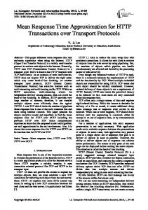
If the process is simulated with a residual flux phi0, the second point of a saturation characteristic is on the coordinate and corresponds to zero value of the current, as shown on figure 4.b. The characteristic of saturation is input with ( i , phi ) values per unit in the system, and with start from couple (0,0). The Power Block (PSB) converts vectors of flux p.u. and vectors of the current I pu into standard units which shall be used in the
pu base , pu / base (64)
sin(t p )}
2.2 Calculation of The Transformer’s Para- Meters The model of the transformer is accomplished, using the software program MATLAB-SIMULINK in such a way that its inputs are vectors of source voltage and source parameters and windings of the transformer, and outputs are vectors of flux, currents of magnetic biasing and variable equations of voltage value of both primary and secondary.
Copyright © 2014 MECS
[Vn ]2 Sn R[] R( p.u ) Rbase []
model of saturation:
sin(t p )} is I pm
effective voltage value Vrms which corresponds to winding.
III. Transients in SIMULINK
Rs 0 Ls
s
Base values are nominal output Sn VA , nominal frequency f n Hz , and nominal voltages Vn V and
The unit value of active resistance of the magnetic circuit Rm is based on indicated power Sn [VA] and on
1 u s dt , N 2 0
In accordance with technical practice it is necessary to determine resistance and inductance of windings in the system per unit.
Rbase
cos(t p )}
Simulation and analysis of the transformer’s behavior in transient processes was preformed in idle operation and is consisted of the described simulation models of voltages and source parameters and transformers along with blocks which simulate voltages of the transformer.
The base unit resistance, and base and unit inductance which are used for each winding are:
sin(t p )}
1
7
I I pu Ibase , I pu I / I base
,
where the base values of flux and current have values which correspond to nominal voltage, power and frequency. Nominal power and frequency: Nominal apparent power Sn VA , and frequency f n Hz , of transformer. Winding parameters 1: Nominal effective value of voltage in V , resistance and drive inductance of winding 1 in p.u.. Winding parameters 2: Nominal effective value of voltage in V , resistance and drive inductance of winding 2 in p.u.. The characteristic of
I.J. Information Technology and Computer Science, 2014, 01, 1-12
8
Computer Simulation of Theoretical Model of Electromagnetic Transient Processes in Power Transformers
saturation-denoted as a flow/diagram of current pair (p.u.)-flux (p.u.) which starts from the point (0,0). Active losses in the core of magnetic circuit and initial flux: Active losses of the power in the core which are included into the resistance parameter Rm in p.u.. For example: Denoting loss of active power as 0,2% at nominal voltage nominal value for Rm 500 p.u. also can be denoted as the initial flux phi0 (p.u). The initial flux has special importance in transformer feeding. If phi0 is not denoted, the initial flux is automatically set for simulation of a steady-state start. The following has been measured: Voltages of windin U1 U p U N 1 ( p.u.) , U 2 U s U N 2 ( p.u.) , Currents of winding: I N1 , I N 2 . Magnetizing current: I mag . Flux: . Outputs and inputs: One input, one output, or three outputs (if they exist) instantly have the same polarity. If on the input, with the third winding equaling 0 is found, then in the block-set it is implemented in the transformer with two windings and magnetic circuit and the display shows an icon which symbolizes a transformer. Limitations: A winding on the icon can vary. A variable winding is internally and directly connected to the resistance in the circuit, and an invisible connection has no influence on voltage and current measurement. The flux saturation model does not include hysteresis, figure 4.b. The circuit is available in the file psbxfosaturable.mdl file.
3.1
V2n 36,75 0,2988 0,3 V1n 123
Reactance of the primary and secondary windings are:
X k1
X k 15.13 7.56 2 2
X k2
X k 2 15,13 0,32 0,68 kt 2 2
Dissipative inductances of primary and secondary are:
L1 L 1
X k1
L2 L 2
X k2
7.56 0,024H 314
0.68 0.0022H 314
Impedance of magnetic biasing is:
V1nV1n
Zm X m
3 i0 % I nV1n
123210 6
V 21n i0 S n
30,26k
0,005 100 10 6
Inductance on the primary side is:
Lm
Xm
30.26 10 3 96,36H 314
Resistance of transformer winding (primary and secondary) is:
Simulation No. 1
Simulation was performed on the real three-phase power transformer SIMENS-ONAF/ONAN (dimensions: length 7800 mm , width 3250 mm , height 6100 mm , transformer has fans which start to work at higher loadings; oil flow depends only on siphon effect) with the following information: connection Yy , current of idle operation i0 % 0,5% , voltage of short circuit
uk % 10,5% , voltages of primary and secondary U np U n1 71.09kV , U ns U n2 21,24kV ,
S n 100MVA , PFe 49kW , Pcun 285 kW , Vnp Vn1 123 110 8%kV , Vns Vn2 36,75kV .
From the primary side, the reactance of the short circuit is:
u % V12n 10 1232 10 6 Xk k 15.13 100 S n 100 100 10 6
R1 R p R1k
1 Pcun 1 Pcun ( 3V1n ) 2 2 2 2 3I1n 2 3 S n
1 Pcun 2 1 285 103 V1n 1232106 0,2156 2 S n2 2 100 21012
R2 Rs R2 k
1 Pcun 1 Pcun ( 3V2 n ) 2 2 3I 22n 2 3 S n2
1 Pcun 2 V2 n 2 S n2
1 285 103 36, 752 106 0, 0194 2 12 2 100 10
Rbase
The ratio of the number of coils of the primary and secondary windings is:
Copyright © 2014 MECS
kt
Lbase
Vn 2 Sn
50.43
Rbase 50.43 0,1606 2f n 314
I.J. Information Technology and Computer Science, 2014, 01, 1-12
Computer Simulation of Theoretical Model of Electromagnetic Transient Processes in Power Transformers
base I base
V1 2f n
Sn V1
2
2
123e3 / sqrt3 sqrt2 3,19Wb 2 50
100e6 sqrt2 1983A 123e3 / sqrt3
9
1.0 1.22], residual flux = 0.6 p.u. is presented as a partially linear curve of flux dependence from the magnetization current Input values which correspond to dialog box are:
The three-phase transformer 100 MVA , 123/36.75 kV is single-phase fed from the resource 50 Hz . Transformer: Nominal power 100e6,50 Hz , parameters of winding 1 (primary): 123e3 Vrms/sqrt(3), R 0,00427 p.u., L 0,145 p.u., parameters of winding 2 (secondary): 36.7e3. Active losses in the magnetic circuit: 1000p.u. Characteristic of saturation: [0 0; 0 1.0;
R1
0.2156 0.004275 p.u . 50.43.
L1
0.024H 0,1494 p.u . 0.1606H
Fig. 4: a) Simulation of idle operation of transformer and b) characteristics of block saturation of saturated transformer
In this simulation process, figure 4 which presents a regime of idle operation of a transformer shows the influence of the characteristic of saturation and time constants of a transformer. In that moment, the values of the flux and magnetization current start to increase which cause the increase of the voltage in the primary and secondary, where the voltage on the secondary transformer can have a higher unit value from the voltage of primary transformer. During the process the time constants of the primary and secondary as well as the nonlinear characteristic of magnetic saturation have the influence. The voltage of the secondary, due to this influence, has a slight increase after a time period of 0,06 s and is permanently stable until the end of simulation, figure 5.
3.2
Simulation No. 2
Figure 6: It simulates the short circuit and only controls the current of the secondary set to the nominal
current I "n 232A , for a real three-phase power transformer SIMENS-ONAF (dimensions: length, width, height 1140x800x1700 mm , transformer has fans which start to work at higher loadings; oil flow depends only on siphon-effect) with the following information: connection Dy 5 , current of idle operation i0 % 1% , voltage of short circuit uk % 3,75% , voltages of primary and secondary U np U n1 10.5kV ,
U ns U n2 230V , S n 160kVA , PFe 500W , Vnp Vn1 10.5kV , , Pcun 3200W
Vns Vn2 0.4kV .
Copyright © 2014 MECS
I.J. Information Technology and Computer Science, 2014, 01, 1-12
10
Computer Simulation of Theoretical Model of Electromagnetic Transient Processes in Power Transformers
u % V12n 3.75 10.5 2 10 6 Xk k 25.8 100 S n 100 160 103 The ratio of number of the coils of the primary and secondary winding is:
kt
U 1n 10,5 45.652 46 U 2n 0.230
The reactance and dissipative inductance of primary winding is:
X k1
X k 25.8 12.9 2 2
L1 L 1
X k1
12.9 0,043H 314
Magnetization impedance is:
V1nV1n
Zm X m
2
10.5 10
3 i0 % I nV1n 6
0,01 160 10 3
V 21n i0 S n
68,9k
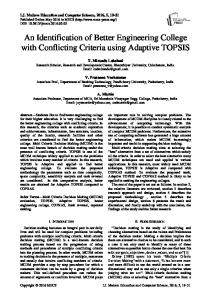
Inductance of magnetization from the primary side is: Fig. 5: Results of simulation no. 1: Time flow of flux, magnetization current and voltages of primary and secondary
Lm
Xm
68.9 103 219,36H 314
From the primary side the reactance of short circuit is:
Fig 6: Results of simulation no. 2: Short circuit is made by adjustment of loading in secondary
Pcun 3200W which was the goal of this
simulation
Copyright © 2014 MECS
I.J. Information Technology and Computer Science, 2014, 01, 1-12
Computer Simulation of Theoretical Model of Electromagnetic Transient Processes in Power Transformers
Resistance of transformer’s primary winding:
R1 R p R1k
has been shown that such a computer simulation in a qualitative way can describe the transient processes and by doing so a better analysis of their behavior can be performed. This paper described dynamic changes in real and ideal power transformer through MATLAB Simulink, which indicates possible malfunction or defect.
1 Pcun 1 Pcun 2 V1n 2 3I12n 2 S n2
1 3200 10.5 210 6 6,89 2 160 210 6
Rbase
Lbase
Vn 2 Sn
10.5 2 10 6
689
160 10 3
11
References [1] B. Mitraković: Transformatori, Beograd, 1985.
Rbase 689 2.194H 2f n 314
[2] Datasheet, online: March http://www.eps.et.tudelft.nl
For this simulation a three-phase transformer ONAN was used, Dy 5 160 kVA , 12(10.5)/0.4 kV is singlephase fed from the resource 50 Hz . Transformer: Nominal power 250e6,50 Hz . Parameters of winding 1 (primary): 10.5e3 Vrms, R 0,01 p.u., L 0,02 p.u., parameters of winding 2 (secondary): 0.4e3 Vrms/sqrt(3), active losses in the magnetic circuit: 50p.u. Characteristic of saturation: [0 0;0 1.0;1.0 1.22], residual flux = 0.6 p.u.
10th
2011,
[3] Van der Sluis, L., Rutgers, W.R., Koreman, C.G.A.: A physical arc model for the simulation of current zero behaviour of high-voltage circuit breakers, IEEE T-PWRD 7(2), 1992, p. 1016–1022. [4] Akademik Antonin Veverka: TECHNIKA VYSOKÝCH NAPĚTÍ SNTL/ALFA, DT621.3027 3:621.315.31:II, Elektrickě razově jevy ve vinutih transforma torů a točivýh strojů, Praha, 1982.
Input values which correspond to dialog box are:
[5] Mayer, D.: ŮVOD DO TEORIE ELEKTRICKÝH OBVODŮ, SNTL/ALFA, 16. Nelinearni obvody sa soustrednimi parametry, Praha, 1978.
6.89 R1 pu 0.01 p.u . 689
[6] Kvasnica, J.: Teorie elektromagnetickeho pole, Kapitola, V.: Kvayistacionárni elektromagneticke polé, ACADEMIA PRAHA, 1985.
0.043H L1 pu 0,02 p.u . 2.194H
[7] MATLAB SIMULINK Sim Power System, Copyright 1984-2002 The Math Works, Version 6.5.0,180913a, June 2, 2000.
The short circuit was simulated with adjusted current of secondary:
I "n
Sn
3Vn
160 103 3 0.4 103
232A
[9] Розенблат М.А.: Магнитные элементы автоматики й вычислительной техники, УДК 538, Наука, Москва, 1974, p. 85–101.
IV. Conclusion The application of a computer simulation of dynamic behavior of a power transformer in the software program MATLAB-SIMULINK at transient processes, the validity of a given theoretical model in extreme regimes as idle operation has been confirmed. Measurement results a) in idle operation- time change of the flux verifies the value of expression (61) time flow of a current of magnetization verifies the value of expression (59), and time flows of voltages of primary and secondary relations (47) and (48) at b) short circuit diagram verifies the value, figure 5. In the first example of a transformer of high power and a second example of a transformer of low power it Copyright © 2014 MECS
[8] Bjelić, S., Marković, N. Jakšić, U.: The simplified procedure for calculation of influence of thermal losses on decrease of technical endurance of electric equipment, III Energy efficiency in application of electricity www.society-of thermal engineering of Serbia, IEEP `2011, ISBN 978-867877-022-7, COBISS.SR-ID 184481804, 2011, Abs. p. 28.
[10] Bjelic, S., Markovic N.: Multisliced-level type phase-comparison carrier relaying system for multi-terminal lines, 16th International Telekommunication forum, TELFOR 2008, Belgrade, Session 7: AEE, work 29, Proceedings, 2008, p. 585. [11] Bjelic, S., Jaksic, U., Markovic, N.: Informatical Model of the System of Automatic Breakdown Control in Energetic Systems, ELEKTRONIKA IR ELEKTROTECHNIKA, Vol. 1, 2011, p. 87–92. [12] Markovic, N., Bjelic, S., Jaksic, U.: Development of new measuring systems based on symmetric components in electric networks, Submission
I.J. Information Technology and Computer Science, 2014, 01, 1-12
12
Computer Simulation of Theoretical Model of Electromagnetic Transient Processes in Power Transformers
ID:37, Journal Arhive Kaunas University Lithuania, ISSN 1392-1215, ELECTRONICS&ELECTRICAL ENGINEERING, T 120, No 8(104), 2010, p. 57–62. [13] Marković, N., Bjelić, S., Jakšić, U.: Calculation of influence of additional losses on decrease of time period of exploitation of power transformer, Inovacije i razvoj, Bor, br. 1, 2011, p. 75–86. [14] Bjelić, S. et al: Estimation of currents flow, loss of power and voltage fall down in distribution network by using PDM KMp.q, 19 International Conference of Electrical Distribution, Paper 0907, Block 4.2, Method and tools, Cired, Wien, 2007. [15] Bjelić, S.: Introduction in middle voltage networks and low voltage installations, BOOK, ISBN 97886-83561-15-5, Cobiss SR-ID 14100 0204 SVEN, Nis, 2007.
Authors’ Profiles Slobodan Bjelić: Professor of electrical engineering at Faculty of Technical Sciences in Kosovska Mitrovica, Serbia
Zorica Bogićević: Post-graduate student for doctor degree in electrical engineering at Faculty of Technical Sciences in Kosovska Mitrovica, Serbia
Copyright © 2014 MECS
I.J. Information Technology and Computer Science, 2014, 01, 1-12