effect of gating system geometries, iron chills, and the melt temperature on the shrinkage and porosity distribution of LPSCed Mg engine blocks have been ...
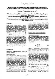
Computer Simulation and Experimental Validation of Low Pressure Sand Casting Process of Magnesium Alloy V6 engine block Yingxin WANG2, Liming PENG1,2, Penghuai FU2, Wenjiang DING1,2 1 Key State Laboratory of Metal Matrix Composite, Shanghai Jiao Tong University, Shanghai 200240 2 National Engineering Research Center of Light Alloy Net Forming, Shanghai Jiao Tong University, Shanghai 200240 Abstract:
292Mpa and 10% respectively.
1. Introduction
Aluminum alloys have commonly used for engine blocks in the past ten years, and continues to rise in automotive industry. In order
With
the
increasing
demands
to
control
to decrease the dioxide carbon emission and fuel
inter-national fuel consumption and reduce
consumption of cars in future, using magnesium
harmful
alloys instead of aluminum alloys for fabricating
automobile manufacturers are being pressured
engine blocks are very attractive for automotive
into developing more fuel efficient vehicles.
industry. This paper reports the development of
Reducing the overall weight of the vehicles is
Mg alloy engine blocks produced by low
the key to achieving this goal. A major
pressure sand casting (LPSC) process with a new
contributor to the weight of vehicle is the engine
heat-resistant JDM1 alloy. For the purpose of
itself, and the most significant component of an
predicating and eliminating the casting defects in
engine is the block, which makes up 20–25% of
Mg engine blocks, the LPSC process is modeled
the total engine weight. Aluminum alloys have
TM
and simulated by Anycasting
emission
into
the
atmosphere,
software. The
commonly used for engine blocks in the past ten
effect of gating system geometries, iron chills,
years, and continues to rise in automotive
and the melt temperature on the shrinkage and
industry for about 50% significant weight
porosity distribution of LPSCed Mg engine
savings made by introducing an aluminum block
blocks have been investigated, and then the
to replace the traditional grey iron block, which
optimum gating system design and LPSC
improves the fuel consumption efficiency and
parameters are obtained. Several engine block
power performance obviously. Further about
castings are practically casted with different
40%reduction
LPSC parameters, and the result of dissecting
magnesium alloy, which could withstand the
the block casting validates the simulation
temperature and stresses generated during the
could
be
achieved
if
a
accuracy very well. Finally, the Mg V6 engine
engine operation, were used for engine blocks[1].
block castings without defects go through GM
This will further improve the fuel consumption
leakage
efficiency and power performance and is very
test
standard
and
shows
good
mechanical properties on bulkhead, with yield
attractive for automotive industry.
tensile
tensile
To devlop a new magnesium alloy engine block,
strength(UTS) and elongation of 151Mpa,
three main problems are needed to be solved: i) a
strength(YTS),
ultimate
suitable material for magnesium engine block; ii)
predicate and eliminate the casting defects in
the structural design for magnesium engine
magnesium engine blocks. Effects of gating
block and iii) the fabrication process of
system geometries, iron chills, and the melt
magnesium engine block. For the first problem,
temperature on the shrinkage and porosity
JDM1 alloy (Mg-3wt%Nd-0.2wt%Zn-0.4wt%Zr)
distribution of LPSCed magnesium engine
[2],
Engineering
blocks were investigated. Finally, using the
Research Center for Light Alloy Net Forming,
LPSC process parameters optimized by the
Shanghai Jiao Tong University, has a better
above
comprehensive mechanical properties used for
magnesium
the sand casting in the fully heat-treated T6
fabricated and their leakage tests and mechanical
condition,
critical
properties on bulkheads were also investigated.
performance of the engine block, as shown in
The casting experimental result validated the
Table 1. For the second problem, through
simulation accuracy very well.
developed
by
which
National
can
meet
the
repeative
simulation
engine
block
work,
sound
castings
were
cooperation with GM Powertrain Lab, a new magnesium
engine
block
structure
was
2. Experimental process
re-designed. And for the third problem, the fabrication process of magnesium engine block
2.1 Simulation process
will be investigated in this paper.
Fig.1 shows the 3D model of Mg engine block cast with LPSC pouring system, as the primary
Table 1: Critical performance of the magnesium
casting case for simulation, named Case 1,
engine block [1]
where 26 inner gates are designed to feed the Mg Room temperature
engine block cast. There is just engine block cast 150℃
177℃
investigate the full defects of the engine block
Yield strength
and gating system but no chills, which used to
120
110
cast. The thermo-physical properties of JDM1
(MPa)
alloy are shown in Fig.2. The initial conditions
Creep
of Case 1 are shown in Table 2 and the LPSC
strength
110
90
Based on the simulation result of Case 1, the
(MPa) Fatigue limit (MPa) Thermal conductivity
processing parameters are shown in Table 3. other several casting cases (i.e. different chills
50
and gating systems) are designed to modify the LPSC parameters.
115W/Km
Creep strength: stress to give 0.1% creep strain after 100 hours. This target was set to be equivalent to the performance of A319.
Cast
Fatigue limit: R= -1,n=5×10⁷ cycles In this paper, magnesium engine blocks were
Gate
fabricated by low pressure sand casting (LPSC) process with a new heat-resistant JDM1 alloy. The process was modelled and simulated by use
Figure 1: 3D model of Mg engine block cast
of AnycastingTM software and self-developed
with pouring system (Simulation case 1)
thermo-phyical property databse, in order to
Table 2: The initial conditions during simulation
Some JDM1 alloy engine blocks were casted
process
according to the LPSC processing parameters Materials
Casting
Initial conditions
JDM1
740℃
suggested by the simulations and dissected for defects validation. Leakage test of the sound JDM1 alloy engine block was done according to
temperature Mold
Silica sand
air
Heat transfer
80℃
the GM HFV6_SOR_Leaktest specification. The
25℃
bulkheads (as shown in Fig.3) are the key
air-mold
5
positions of the engine block which suffers a
air-cast
11
huge load as the engine works and their mechanical properties were tested. After the
cast-mold
coefficient
400
solution treatment (540℃,10h) and the aging
100
treatment (200℃,time varied from 0.5h to 24h),
(W/m2K) fractio 640℃
the tensile test samples were cut into rectangular tensile specimens with an electric-sparking
Table 3: LPSC processing parameter for Mg
wire-cutting machine and details were shown in Fig.4. Tensile testing was carried out on a
engine block using JDM1 alloy during
Zwick/Roell
simulation process LPSC stage
Pressure/MPa
Time/s
Rising stage
0.015
20
Filling stage
0.025
17
Increasing stage
0.065
15
Dwelling stage
0.065
300
Total time
material
test
machine
at
cross-head speed of 0.2 mm/min at room temperature.
352
Figure 3: The location of the mechanical properties test on the bulkhead
Figure 4: The shape and size of the tensile Figure 2: Thermophysical properties of JDM1 alloy 2.2
specimen
3. Results and discussion Defect
property test
validation
and
mechanical
a
3.1 simulation and defects validation results
Fig.5 shows the filling sequence of JDM1 alloy
time of engine block cast is about 365s, which is
engine block for Simulation Case 1. The full
a little larger than that shown in Table 3.
basin runner, almost all of 26 ingates and a small part of engine block cast are filled with a filling fraction of 45% at 7.8s, as seen in Fig.5a. The melt surface has a little fluctuation for large difference of wall thickness of engine block cast as 55% to 75% filling fraction, as shown in Fig.5b and c. The engine block cast is filled soundly at 17.3s (as shown in Fig.5d). As a whole, the JDM1 alloy melt enters into the 26
(a) solidification time=61s and a solidification fraction of 5%
(b) solidification time=108s and a solidification fraction of 10%
ingates through the basin runner and then fill the whole engine block cast smoothly, which presents the characteristics of LPSC process. The full filling time shows a good agreement with the set filling stage in Table 2. The solidification sequence of JDM1 alloy engine block
cast
in
Fig.6
shows
a
sequential
solidification basically. The bottom part (i.e. the
(c) solidification time=156s and (d) solidification time=203s and a solidification fraction of 15% a solidification fraction of 20%
top side of figure) of engine block cast solidifies firstly (Fig.6a and b), and then the bulkhead (Fig.6c and d), finally, the whole engine block cast except for some isolated melt regions (Fig.6e and f), which leads to shrinkage defects of
engine
block
cast.
Fig.7
shows
the
probabilistic shrinkage defects estimated by Retained Melt Modulus. The total solidification
(e) solidification time=251s and (f) solidification time=298s and a solidification fraction of 25% a solidification fraction of 30%
Figure 6: The solidification sequence of JDM1 alloy engine block for Simulation Case 1
It is easy to see that, the shrinkage defect-1 of Fig.7a
connects
to
one
of
the
ingates,
defects-2,3,4,5 and 10 occur on the positions of thick-thin wall junctions, defects-6,7,8 and 9, on (a) filling time=7.8s and a fill
(b) filling time=10.4s and a fill fraction of 60%
the thick positions of engine block cast. All those defects come from the lack of feeding of melt during the solidification of the casting.
(c) filling time=13.0s and a fill fraction of 75%
(d) filling time=17.3s and a fill fraction of 100%
Figure 5: The filling sequence of JDM1 alloy engine block for Simulation Case 1
Chill-2 Defect-1
Chill-1
Defect-3 Defect-2
Figure 8: Simulation case 2 of JDM1 alloy engine block cast Therefore, based on the simulation results of Case 1, Simulation Case 2 is designed and shown in Fig.8: the bulkhead chill (named
Defect-4
chill-1 in Fig.8) and bottom chill (named chill-2 in Fig.8) are added on the thick parts of the bottom of engine block cast to see if the shrinkage defects can be removed. The initial Defect-5
conditions and the LPSC processing parameters for JDM1 alloy engine block during this simulation process is same to that in Simulation
Defect-6
Defect-7
Case 1 and the initial conditions of chills are listed in Table 4. Meanwhile, the JDM1 alloy engine block cast was casted according to the LPSC processing parameters of Simulation Case
Defect-8
2 to make the defect validations. The filling sequence of Simulation Case 2 is similar to that of Simulation Case 1 except for the final fill, as shown in Fig.9d. The engine block cast has not been filled soundly, that is, formation of cold shut on the bottom (bulkhead) of engine block, which is brought by the addition of chills. The
Defect-9
total solidification time of engine block cast is about 319s, which is smaller than that shown in Table 3 due to the addition of chills. Fig.10 Defect-2
shows the comparison between the probabilistic shrinkage defects predicted by Retained Melt Modulus method and the real casting defects in
Defect-10 Defect-7
the block which is fabricated according to the parameters in Simulation Case 2 . It can be concluded that, the shrinkage defects 1,2,3,4,5
Figure 7: Probabilistic shrinkage defects of
and 10 in Fig.7 have no change, the shrinkage
engine block cast as a simulation case 1
defects 6,8 and 9 disappear, the shrinkage defect
7 changes to porosity and a new porosity defect Defect-1
11 occurs. From dessecting block cast, it can be can that Defects 1,2,3,4,5 and 10 occur in real engine block cast, and cold shuts are also found on the bottom of engine block cast, which validates the simulation accuracy. Table 4: The initial conditions of chills Materials chill Heat
Initial conditions
iron
80℃ Defect-3
chill-cast 6000
Defect-2
transfer coefficient (W/m2K)
1000 580℃
chill-mold
640℃
500
Defect-10
Defect-5 Defect-4
(a) filling time=7.7s and a fill fraction of 45%
(b) filling time=10.3s and a fill fraction of 60%
Defect-7 Defect-11
(c) filling time=13.1s and a fill fraction of 75%
(d) filling time=17.2s and a fill fraction of 100%
Figure 9: The filling sequence of JDM1 alloy engine block as a simulation case 2
Figure10: Probabilistic and real shrinkage defects of JDM1 alloy block cast in Case 2
Due to the formation of cold shut and still existing shrinkage defects in Simulation Case 2, another 12 ingates are added and ingate connecting to shrinkage defect-1 is enlarged to enhance the melt feeding capacity during the solidification, named Simulation Case 3 as shown in Fig.11. The initial conditions and the LPSC processing parameters for JDM1 alloy engine block during simulation process is same
Figure 11: Simulation case 3 of JDM1 alloy
to that in Simulation Case 2.
engine block cast
The engine block cast can be filled soundly and
Passages
the total solidification time is about 400s, larger
Oil drains
15cc/min@25kPa
than that shown in Table 3. The probabilistic shrinkage defects estimated by Retained Melt Modulus method show that shrinkage defects-1
Defect-2
Defect-5
Defect-2
and 3 disappear and other defects in Simulation Case 2 still exist in Case 3. Hence, simulation
Defect-4
case 4 is designed base Case 3 as following: the cast pouring temperature is changed to 760℃,
Defect-2
the dwelling stage is 400s for a total time of 452s, other LPSC parameters are same to Defect-10
simulation case 3. The engine block cast can be filled
soundly
and
the
total
calculated Figure 12: Probabilistic
solidification time is about 456s, similar to the
shrinkage
designed. The probabilistic shrinkage defects
defects
estimated by Retained Melt Modulus method are
Case 4
shown in Fig.12. Shrinkage defect-2 has no change, but shrinkage defects 4,5 and 10 decrease and defects 7 and 11 disappear.
Chill-4
To eliminate the shrinkage defects 2,4,5 and 10, Simulation Case 5 is designed and shown in
Chill-3
Fig.13: chill-3 for shrinkage defect-2, bore chill-4 for defects 4,5 and 10 are added, other LPSC parameters are same to simulation case 4.
Figure 13: Simulation Case 5 of JDM1 alloy
Fig.14 shows the probabilistic shrinkage defects
engine block cast
estimated by Retained Melt Modulus. It can be seen that all of shrinkage defects are eliminated. Sound JDM1 alloy engine block is casted successfully according to the LPSC parameters in simulation case 5, as shown in Fig.15. Figure 14: Probabilistic shrinkage defects of 3.2 Leakage test of JDM1 alloy engine block
JDM1 alloy engine block cast in Simulation
Leakage test of the sound JDM1 alloy engine
Case 5
block
was
made
according
to
the
GM
HFV6_SOR_ Leaktest specification, as shown in Table 5. The sound JDM1 alloy engine block can meet
the
requirement
of
the
HFV6_SOR_Leaktest specification. Table 5: Leaktest specification of engine block Feature
Allowable Leak Rate
Water Jacket/Coolant
10cc/min@140kPa
High
Pressure
Figure 15: The sound JDM1 alloy engine block 3.3 Mechanical properties of bulkhead The mechanical properties of JDM1 alloy engine
Passages (4) Oil
12cc/min@140kPa
of
block cast in Simulation
block bulkhead under different conditions at
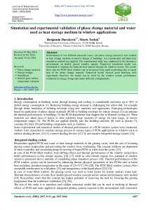
room temperature is shown in Fig.16, it
1. The sound JDM1 alloy engine blocks were
demonstrated that the alloy has a lower
casted successfully according to the optimum
mechanical strength as cast and T4 condition.
gating system,
The as-cast YTS (Yield Tensile Strength), UTS
processing parameters obtained through the
(Ultimate Tensile Strength) and elongation is
casting simulation process using AnycastingTM
77Mpa, 156MPa and 8.4%. After T4 heat
software. And the probabilistic shrinkage defects’
treatment, those increase to 87Mpa, 206MPa and
validation were confirmed by the real cast
19.4%. The UTS and YTS increase gradually
dissection.
with increasing aging time form 0.5h to 12h, and
2. The sound JDM1 alloy engine block can meet
reach the peak value of 292MPa and 151Mpa
the requirement of the HFV6_SOR_Leaktest
respectively. Both of UTS and YTS have a little
specification. The yield strength of bulkhead can
decrease for a long aging time of 24h. The
meet the critical yield strength of the engine
elongation keeps 10% nearly in the whole aging
block and the YTS, UTS and elongation are
process. It can be seen that the yield strength can
151MPa, 292MPa and 10% respectively.
chills position and
LPSC
meet the critical yield strength of the engine
Acknowledgments
block as shown in Table 1. The fatigue property test of the bulkhead area were also done according to ASTM E466-07 specification, and
This work was conducted under an alliance
shows
fatigue
between National Engineering Research Center
strength of the block castings at RT and 150°C:
good
tension-compression
of Light Alloy Net Forming, Shanghai Jiao Tong
90MPa and 70MPa respectively[3].
University and Powertrain Lab, General Motor, US. The authors appreciate the provision of the 3D structure model of V6 engine block from GM.
References 1.
C.J.Bettles,
C.T.Forwood,
D.S.Jones,
J.R.Griffiths, M.T.Frost, D.H.St.John, Ma Qian, G-L.Song,
J.F.Nie,
AMC-SC1:
A
New
Figure 16: Tensile properties of JDM1 alloy bulkhead
Magnesium Alloy Suitable for Powertrain
at room temperature in different conditions: F(as cast),
Applications, SAE paper No. 2003-01-1365.
T4(solution treated, 540℃×10h), 0.5h (solution and
2. Fu Penghuai, Peng Liming, Jiang Haiyan,
aging treated, 540 ℃ ×10h+200 ℃ ×0.5h) to 24h
Chang Jianwei, Zhai Chunquan, Effects of heat
means T6 treatment.
treatments
on
the
microstructures
and
mechanical properties of Mg–3Nd–0.2Zn–0.4Zr
Conclusions
(wt.%) alloy.Mater Sci Eng A, 486(2008), pp183-192.
The effect of gating system geometries, iron
3. Z.M. Li, Q.G. Wang, A.A. Luo, L.M. Peng*,
chills, and the melt temperature on the shrinkage
P.H. Fu,Y.X. Wang Improved
and porosity distribution of LPSCed JDM1 alloy
fatigue properties of a new magnesium alloy.
engine blocks have been investigated, it can be
Mater. Sci.Eng. A,
concluded that:
high
cycle
A 582 (2013) 170–177.