Computer Simulation of Wind Power Systems: Power Electronics and Transient Stability Analysis R. Melício, V. M. F. Mendes, J. P. S. Catalão
Abstract--This paper is concerned with the transient stability of variable-speed wind turbines with permanent magnet synchronous generators at a pitch control malfunction. As wind power generation undergoes rapid growth, new technical challenges emerge: dynamic stability and power quality. We study the influence of a pitch control malfunction on the quality of the energy injected into the electrical grid, analyzing the transient stability with different topologies for the power-electronic converters. Computer simulations obtained by using Matlab/Simulink are presented, and conclusions are duly drawn. Keywords: computer simulation, power electronics, transient stability, wind power.
T
I. INTRODUCTION
HE general consciousness of finite and limited sources of energy on earth, and international disputes over the environment, global safety, and the quality of life, have created an opportunity for new more efficient less polluting wind and hydro power plants with advanced technologies of control, robustness, and modularity [1]. In Portugal, the wind power goal foreseen for 2010 was established by the government as 3750 MW and that will constitute some 25% of the total installed capacity by 2010 [2]. This value has recently been raised to 5100 MW, by the most recent governmental goals for the wind sector. Hence, Portugal has one of the most ambitious goals in terms of wind power, and in 2006 was the second country in Europe with the highest wind power growth. Power system stability describes the ability of a power system to maintain synchronism and maintain voltage when subjected to severe transient disturbances [3]. As wind energy is increasingly integrated into power systems, the stability of already existing power systems is becoming a concern of utmost importance [4]. Also, network operators have to ensure that consumer power quality is not compromised. Hence, the total harmonic distortion (THD) should be kept as low as possible, improving the quality of the energy injected into the electrical grid [5].
The development of power electronics and their applicability in wind energy extraction allowed for variablespeed operation of the wind turbine [6]. The variable-speed wind turbines are implemented with either doubly fed induction generator (DFIG) or full-power converter. In a variable-speed wind turbine with full-power converter, the wind turbine is directly connected to the generator, which is usually a permanent magnet synchronous generator (PMSG). Harmonic emissions are recognized as a power quality problem for modern variable-speed wind turbines. Understanding the harmonic behavior of variable-speed wind turbines is essential in order to analyze their effect on the electrical grids where they are connected [7]. Variable-speed wind turbines usually employ active pitch control, where blade pitch angle increases reduce the captured wind power by reducing the angle of attack [8]. The pitch control may have a considerable effect on the dynamical behavior of wind generators. However, previous papers were mainly focused on the transient stability of variable-speed wind turbines at external grid faults [8], [9]. This paper focuses on the transient stability of variablespeed wind turbines with PMSG at a pitch control malfunction. Hence, we study the influence of a pitch control malfunction on the quality of the energy injected into the electrical grid, analyzing the transient stability with different topologies for the power-electronic converters. Additionally, we propose a new control strategy based on fractional-order controllers for the variable-speed operation of wind turbines with PMSG/full-power converter topology. The performance of disturbance attenuation and system robustness is ascertained. Computer simulations obtained by using Matlab/Simulink are presented, and conclusions are duly drawn. II. MODELING A. Wind Turbine The mechanical power of the wind turbine is given by Pt =
1 ρ A u3 c p 2
(1)
where ρ is the air density, A is the area covered by the rotor, R. Melício and J. P. S. Catalão are with the University of Beira Interior, Covilha, Portugal (e-mail of corresponding author:
[email protected]). V. M. F. Mendes is with the Instituto Superior de Engenharia de Lisboa, Lisbon, Portugal. Paper submitted to the International Conference on Power Systems Transients (IPST2009) in Kyoto, Japan June 3-6, 2009
u is the wind speed value, and c p is the power coefficient. The power coefficient c p is a function of the pitch angle θ of rotor blades, and of the tip speed ratio λ , which is the ratio between blade tip speed and wind speed upstream of the rotor.
For the simulation of pitch control malfunction, we consider that the pitch angle control of the blades imposes momentarily the position of wind gust on the blades, i.e., the blades go to the maximum pitch angle. The maximum pitch angle θ max = 55º is given for the minimum power coefficient, given by cp
= 0.0025
min
(2)
λ = 3.475
(3)
During the conversion of wind energy into mechanical energy, various forces (e.g. centrifugal, gravity and varying aerodynamic forces acting on blades, gyroscopic forces acting on the tower) produce various mechanical effects [10]. The mechanical eigenswings are mainly due to the following phenomena: asymmetry in the turbine, vortex tower interaction, and eigenswing in the blades. The mechanical part of the wind turbine model can be simplified by modeling the mechanical eigenswings as a set of harmonic signals added to the power extracted from the wind. Therefore, the mechanical power of the wind turbine disturbed by the mechanical eigenswings may be expressed by 3 ⎡ ⎤ ⎛ 2 ⎞ Ptt = Pt ⎢1 + AK ⎜ a Km g Km (t ) ⎟ hK (t )⎥ ⎜ ⎟ ⎠ ⎣⎢ K =1 ⎝ m =1 ⎦⎥
∑
(4)
t g Km = sin ⎛⎜ ∫ m ωK (t ' ) dt ' + ϕ Km ⎞⎟ 0 ⎝ ⎠
(5)
where K is the kind of the mechanical eigenswing excited in the rotating wind turbine, m is the harmonic of the given eigenswing, AK is the magnitude of the eigenswing, g Km is the distribution between the harmonics in the eigenswing, aKm is the normalized magnitude of g Km , hK is the modulation of eigenswing, ωK is the eigenfrequency of the eigenswing, and ϕ Km is the phase of the harmonic. The frequency range of the wind turbine model with mechanical eigenswings is from 0.1 to 10 Hz. The values used for the calculation of Ptt are given in Table I [11]. TABLE I MECHANICAL EIGENSWINGS EXCITED IN THE WIND TURBINE K
Source
AK
1
Asymmetry
0.01
2
Vortex tower interaction
0.08
3
Blades
0.15
ωK ωt
3 ωt
9π
⎡ ⎤ u = u0 ⎢1 + ∑ AK sin (ωK t )⎥ ⎢⎣ ⎥⎦ K
(6)
where u0 is the wind speed value, u is the wind speed value
for the tip speed ratio given by
∑
B. Wind Speed The wind speed usually varies considerably and has a stochastic character. The wind speed variation can be modeled as a sum of harmonics with frequency range 0.1–10 Hz [10]
hK
1
1
1/2 (g11+g21)
m
aKm
ϕ Km
1
4/5
0
2
1/5
π/2
1
1/2
0
2
1/2
π/2
1
1
0
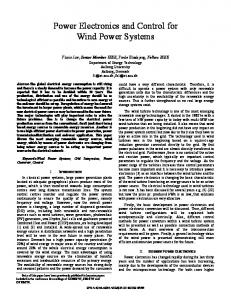
subject to the disturbance. Hence, the physical wind turbine model is subjected to the disturbance given by the wind speed variation model [11]. C. Rotor The mechanical drive train considered in this paper is a two-mass model, consisting of a large mass and a small mass, corresponding to the wind turbine rotor inertia and generator rotor inertia, respectively. The model for the dynamics of the mechanical drive train for the wind power system used in this paper was previously reported by the authors in [12], [13]. D. Generator The generator considered in this paper is a PMSG. The equations for modeling a PMSG can be found in the literature [14]. The electrical power Pe was reported in [12], [13]. In order to avoid demagnetization of permanent magnet in the PMSG, a null stator current id = 0 is imposed [15]. E. Two-level Converter The two-level converter is an AC-DC-AC converter, with six unidirectional commanded IGBTs S ik used as a rectifier, and with the same number of unidirectional commanded IGBTs used as an inverter. The rectifier is connected between the PMSG and a capacity bank. The inverter is connected between this capacity bank and a first order filter, which in turn is connected to an electrical grid. The groups of two IGBTs linked to the same phase constitute a leg k of the converter. A three-phase active symmetrical circuit in series models the electrical grid [12], [13]. The configuration of the simulated wind power system with two-level converter is shown in Fig. 1.
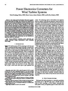
F. Multilevel Converter The multilevel converter is an AC-DC-AC converter, with twelve unidirectional commanded IGBTs S ik used as a rectifier, and with the same number of unidirectional commanded IGBTs used as an inverter. The rectifier is connected between the PMSG and a capacity bank. The inverter is connected between this capacity bank and a second order filter, which in turn is connected to an electrical grid. The groups of four IGBTs linked to the same phase constitute a leg k of the converter. A three-phase active symmetrical circuit in series models the electrical grid [12], [13]. The configuration of the simulated wind power system with multilevel converter is shown in Fig. 2.
Fig. 1. Wind power system with two-level converter.
Fig. 2. Wind power system with multilevel converter.
III. CONTROL STRATEGY
A. Fractional-Order Controller We propose a new control strategy based on fractionalorder PI α controllers for the variable-speed operation of wind turbines with PMSG/full-power converter topology. Fractional-order controllers are based on fractional calculus theory, which is a generalization of ordinary differentiation and integration to arbitrary (non-integer) order [16]. The fractional-order differentiator can be denoted by a general operator a Dtα [17], given by ⎧ dα ⎪ ℜ(α) > 0 , ⎪ dt α ⎪ α ℜ(α) = 0 1, a Dt = ⎨ ⎪t ⎪ (dτ) − α , ℜ(α) < 0 ⎩⎪ a
∫
(7)
There are two commonly used definitions for the general fractional differentiation and integration, respectively, the Grünwald–Letnikov definition and the Riemann–Liouville definition. The differentiation using the Grünwald–Letnikov definition is given by [(t − a ) h ] ⎛α⎞ 1 α = ( ) lim (−1) j ⎜⎜ ⎟⎟ f (t − jh) (8) D f t a t ∑ α h →0 h ⎝ j⎠ j =0 The differentiation using the Riemann–Liouville definition is given by α a Dt f (t ) =
dn 1 Γ(n − α) dt n
t
f (τ)
∫ (t − τ)α − n +1 dτ
(9)
a
where α can be an integer, rational, irrational, or complex number, but in our paper it is a real number satisfying the restrictions 0 < α < 1 , a and t are the limits of the operation. Usually a can be taken as a null value, Γ is the gamma function and h is the step.
The differential equation of the fractional order controller is given by
y (t ) = K p e(t ) +
K i 0 Dt− α
e(t )
(10)
where K p is the proportional gain and K i is the integration gain. We assume α = 7 10 , and for simplicity we write 7 10 0 Dt
≡ Dt7 10 . Using the Laplace transform, the transfer
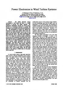
V. SIMULATION The wind power system simulated has a rated electrical power of 900 kW. The mathematical models for the wind power system with the two-level and multilevel converters were implemented in Matlab/Simulink. The parameter α has been chosen within [0,1] and equal to 7/10. The configuration of the fractional-order PI 7 10 controller is shown in Fig. 3.
function of the fractional-order PI α controller is given by −
7 10
(11)
B. Converters Control Power converters are variable structure systems, because of the on/off switching of their IGBTs. As mentioned previously, the controllers used in the converters are fractional-order PI α controllers. Pulse width modulation (PWM) by space vector modulation (SVM) associated with sliding mode is used for controlling the converters. The sliding mode control strategy presents attractive features such as robustness to parametric uncertainties of the wind turbine and the generator as well as to electrical grid disturbances [18]. Sliding mode controllers are particularly interesting in systems with variable structure, such as switching power converters, guaranteeing the choice of the most appropriate space vectors. Their aim is to let the system slide along a predefined sliding surface by changing the system structure. The power semiconductors present physical limitations, since they cannot switch at infinite frequency. Also, for a finite value of the switching frequency, an error eαβ will exist between the reference value and the control value. In order to guarantee that the system slides along the sliding surface S (eαβ , t ) , it is necessary to ensure that the state trajectory near the surfaces verifies the stability conditions given by S (eαβ , t )
dS (eαβ , t ) dt