may be overlaid, or it could be an auto-mechanic who has ... of the predefined gesture classes. ... based on a pixel representation learned from training im- ages.
In 4th IASTED International Conference on VISUALIZATION, IMAGING, AND IMAGE PROCESSING, pages 766-771, Marbella, Spain, Sep 2004
COMPUTER VISION-BASED GESTURE RECOGNITION FOR AN AUGMENTED REALITY INTERFACE Moritz Störring, Thomas B. Moeslund, Yong Liu, and Erik Granum Computer Vision and Media Technology Laboratory, Aalborg University Niels Jernes Vej 14, DK-9220 Aalborg East, Denmark {mst,tbm,yliu,eg}@cvmt.aau.dk ABSTRACT Wearable computing and Augmented Reality applications call for less obtrusive and more intuitive human computer interfaces than keyboards and mice. One way to realise such interfaces is using gestures, e.g., for pointing in order to replace the mouse. The less obtrusive way of gesture recognition is to use computer vision based methods. This paper presents a computer vision-based gesture interface that is part of an Augmented Reality system. It can recognise a 3D pointing gesture, a click gesture, and five static gestures. A lookup-table based colour segmentation and a fast gesture recognition method are presented that enable for 25Hz performance on a standard PC.
HMC HMD PHO
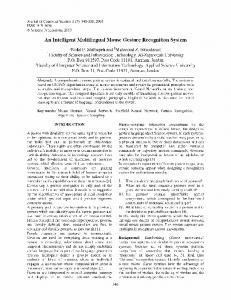
Figure 1. User doing a pointing gesture and wearing an HMD with two HMC.
KEY WORDS Computer Vision, Face and Gesture Recognition, HumanComputer Interaction, Augmented Reality
1
Another requirement is to have some kind of interface to the AR-system generating the graphics, e.g., when to add/remove the overlaid graphics. Many different approaches have been tried but so far the interface has not been constructed. However, it seems evident that hand gestures will be a part of the interface, as they are always ’at hand’ and they can provide deictic information in an easy and precise manner which modern WIMP interfaces1 have proven to be a necessity. In this paper we present an HMCbased gesture interface which is used in AR applications.
Introduction
In the last decade the idea of having computers located other places than on our desktops has been widely accepted, and terms such as pervasive computing and ubiquitous computing have become part of the vocabulary of many researchers. One aspect of this development is when the computer is worn by a human, commonly referred to as wearable computing. Among other things the notion of wearable computing covers the idea of using this worn computer to enhance the human visual sensors, the eyes, by augmenting artificially generated information on the visual input. Currently this is done by having the user wear a HMD (head mounted display) showing the real world and then overlay graphics on the HMD. This is known as AR (augmented reality) and has many applications, e.g., the surgeon who is operating a patient and meanwhile has the primary bio-parameters for the patient overlaid on his seethrough HMD – even the MR-images recorded yesterday may be overlaid, or it could be an auto-mechanic who has the proper voltage and current values overlaid on the wires he is currently looking at. The latter application example requires knowledge of the viewpoint of the HMD in order to align the overlaid data correctly, which is a requirement in many AR applications. A common approach is to use computer vision-based on the input from one or two HMC (head mounted cameras) mounted on the HMD (figure 1).
1.1
Related Work
Recognition of gestures consists of two steps: 1) capturing the motion and configuration/pose of fingers, hands, and/or arms, depending on the level of detail required (hereafter: hand), and 2) classify the captured data as belonging to one of the predefined gesture classes. A number of different devices have been applied in order to capture the data, e.g., magnetic devices, accelerometers, and bend sensors, but in general the capturing is either performed by a glove-based system, see e.g., [1], or by an optical-based system. Due to the non-intrusive nature of the latter it is the focus in much gesture research, including this paper. Optical-based gesture recognition systems may be divided into two overall categories: Model-based and 1 WIMP = Windows, Icons, Menu, Pointer. The most widely used Graphical User Interface on desktop computers and Hand-Helds (PDA).
1
appearance-based. In a model-based system a geometric model of the hand is created. This model is matched to the (preprocessed) image data in order to determine the state of the tracked hand. The model can be more or less elaborate, from the 3D model with 27 DoF (degrees-of-freedom) used in the DigitEyes system [2] over the cardboard model used in [3] to a contour model of the hand seen straight on in [4]. Continuously fitting the model to the hand in the video frames is a process of tracking the complete state of the hand and not just its position. This process is consequently called state based tracking. If the model contains a sufficient number of internal DoF, recognition of static gestures can be reduced to inspection of the state. In appearance based approaches the recognition is based on a pixel representation learned from training images. As no explicit model of the hand exists all the internal DoF will not have to be specifically modelled. However, this also means that differentiating between gestures is not as straight forward as with the model based approach. The gesture recognition will therefore typically involve a (statistical) classifier based on a set of features that represent the hand. Since a pixel-based representation of the hand is quite comprehensive a representation via Principal Component Analysis is often applied, see e.g., [5, 6]. Both approaches require a relative high computational complexity which is undesirable in an AR interface where close to real-time performance and low computational complexity is required due to the other systems that are to be driven by the wearable computer, e.g., graphics for the HMD and six DoF localisation of the head with respect to the world. To some extent this can be overcome by introducing signal-to-noise enhancements like markers on the fingers and hands, e.g., [7], or Infrared lighting [8]. For additional information regarding previous gesture recognition systems in computer vision in general and in AR in particular see [9, 10, 11, 12, 13]
1.2
of different gestures in order to make a useful interface, and have a low computational complexity. This should be achieved without introducing any enhancements like markers and Infrared lighting. In particular, we show in this paper how a computational simple yet reliable gesture recognition system can be designed, and we test it in a concrete AR interface. The paper is structured as follows: The gestures to be recognised are defined in section 2. In section 3 the segmentation of the images is described, and section 4 explains the gesture recognition. In section 5 the system performance is presented and in section 6 a conclusion is given.
2
Defining the Gestures
Like most AR interface designers we believe that a good gesture interface as a minimum requires a pointing and a click gesture. The primary argument for this is that many applications may be controlled through these two gestures. However, in order to avoid numerous pop-up menus for all kinds of interactions the interface should also include other gestures, such as shortcut commands. Furthermore, is should be easy for the user to remember how to perform these gestures. Thinking in terms of the pointing gesture, the most natural way to performing this is by an outstretched index finger. The above requirements for the additional gestures combined with this pointing gesture let to the idea of defining five additional gestures by associating each with a number of outstretched fingers. This idea let to the definition of the gesture-set illustrated in figure 2, which is an easy-toremember set of gestures that provides a rich enough vocabulary to create interesting and useful interfaces.
Context of this Paper
The gesture recognition system presented in this paper is part of an AR project which goal is to develop a multi-user AR system for round-table meetings, e.g., for architects, see [14] for additional information. Within this AR system an interface is build based on PHO (placeholder objects), pointing devices/wands, and gestures. PHO are physical objects located on a table that are tracked in position and orientation in the table plane (3DoF), whereas pointers are tracked in up to 6DoF. By moving PHO different parameters in the system may be controlled, e.g., the position or scale of a virtual object. PHO, pointer, and gestures are recognised by colour-based computer vision.
Figure 2. The six gestures applied in this work. From a technical point-of-view this set of gestures is likely to be recognisable as all gestures may be distinguished in a plane. If we ask the users only to perform the gestures in this plane, then the recognition problem is reduced from 3D to 2D, hence, an easier problem to solve. This might seem a hard limitation for the system, but as the gestures are all related to a plane, we found that different users quickly adapted to this constraint. Furthermore, our recognition method, which will be presented in section 4, is not as sensitive to small rotations (around any of
1.3 Focus of this Paper The focus of this work is to develop a gesture recognition system. The system should contain a sufficient number 2
the three rotational axes) of the hand as is usually seen in other recognition systems. In other words this is only a soft constraint. Our recognition method relies on a pre-segmented image of the hand, which is described in the next section.
by dividing the RGB elements with their first norm: r=
G B R , g = , b = , N = (R + G + B) N N N
(1)
a mapping from 3D space to a 2D plane (r + g + b = 1). Figure 4 shows the rg-distributions of the different colours in camera input image (figure 3.A).
3 Segmentation The task of the low-level segmentation is to detect and recognise the above mentioned PHO and pointers, as well as hands in the 2D images captured with the HMC (figure 3.A shows an example input image). Since both, camera and objects, may move with respect to each other the 2D projection of the objects may vary considerably in size and form. Furthermore, the form of the hand changes also depending on the gesture. In order to achieve invariance to changing size and form of the objects to be detected we use a colour pixel-based approach to segment blobs of similar colour in the image. Compared to gray tone methods colour has the advantage of providing extra dimensions, i.e., two objects of similar gray tones might be very different in a colour space [15].
1
Background
chromaticity g
0.8
0.6
Skin 0.4
0.2
0 0
0.2
0.4 0.6 chromaticity r
0.8
1
Figure 4. Chromaticity plane showing the r and g components of the colours to be detected. Colours within the ellipses are labelled as the respective object colour. The distributions within the ellipse are measured chromaticity distributions of hand and object colours.
A
These distributions are each modelled as a unimodal 2D Gaussian, i.e., their mean values and covariance matrices are estimated, which is done during an initialisation step. From these mean values and covariance matrices we calculate confidence ellipses (confidence ellipses are shown in figure 4). When segmenting an image it is tested whether the rg-chromaticity of a pixel is within one of the confidence ellipses using Mahalanobis distance. A recursive region growing is used to find connected areas in the image, and several features such as centre of mass and bounding boxes are calculated. The segmentation result using only the ellipse for skin colour is shown in figure 3.B. It can be seen that not only the hand but also other objects are detected as skin colour. Therefore we have defined that a skin blob has a certain minimum and maximum number of pixels. Also, there are some pixels within the hand that are not detected as skin, which may be due to camera noise. These are removed with an opening (morphology) filter. The final segmentation result of the image in figure 3.B can be seen in figure 6.B (ignore the concentric circles).
B
Figure 3. A: HMC input image showing PHO, a pointer and a gesture. B: Skin colour segmented image.
A problem when using colour as a feature is that the colour appearance of objects depends on the illumination the objects are exposed to. Illumination changes may be divided into intensity changes and colour changes. Intensity changes may be due to the light source itself or due to changing illumination geometry, e.g., distance to the light source. Illumination colour changes are due to the different spectral composition of light sources, e.g., daylight, fluorescent light, or tungsten light. An often used approach to achieve invariance to changing intensities is to transform the RGB colours to a colour space that separates the intensity from the colour information [16]. Such colour spaces are, e.g., HSV and normalised RGB. The problem of changing illumination colour is more complex than intensity changes and cannot be solved with a simple transformation. In this work it is therefore assumed that there are mainly intensity changes, but only small changes in the colour of the illumination. We use normalised RGB, also called chromaticities, to achieve invariance to the intensity, which are calculated
3.1
Implementation Issues
When implementing this method there are several issues to be considered. Cameras have a limited dynamic intensity range. For low RGB camera responses there is usually a high level 3
4
of noise which makes the calculation of chromaticities unreliable. Therefore only√pixels with a minimum intensity Imin should be used: R2 + G2 + B 2 > Imin . For a 24bit RGB output (8bit per channel) we used Imin = 30. Also for high RGB camera responses, when one or several elements of a pixel are overexposed, the colour information becomes distorted. Therefore we checked that each channel is less than 255 (8bit). Pixels which have at least one element = 255 are ignored. Since cameras often have a non-linear intensity response2 at high RGB outputs the maximum may be set to an even lower value, e.g., 240. Using the above explained method includes per pixel several multiplications, divisions, relational operators (less/greater than), and summations to calculate the rg-chromaticities. Furthermore, up to n Mahalanobis distances need to be calculated, where n is the number of different colours to be detected, in our example n = 7. In order to reduce the required processing we pre-calculate a 3D RGB lookup table (LUT) during an initialisation step. The rg-chromaticity ellipses in figure 4 become cones in RGB space that are truncated by the camera’s dynamic range and the minimum intensity as shown for two colours in figure 5. The triangle in the RG-plane (spanned by the R and G axis and the dash-doted line) is the chromaticity plane with two confidence ellipses (also shown in figure 4).
Gesture Recognition
After having segmented the hand pixels from the image, the task is now to find which gesture, if any, is performed. How this is done is described in this section. The approach is divided into two steps corresponding to two different algorithms, one which detects the number of outstretched fingers and one which handles the point and click gestures.
4.1
Count the Number of Fingers
In figure 2 it can be seen that the hand and fingers can be approximated by a circle and a number of rectangles, where the number is equal to the number of outstretched fingers. From this observation it follows that a very simple approach to counting the number of outstretched fingers is to do a polar transformation around the centre of the hand3 and count the number of fingers (rectangles) present in each radius. As the gestures are only performed while the hand is pointing upwards, only the interval [180◦ , 360◦ ] is investigated. In figure 6.A a polar transformation of the upper half of figure 3.B is shown, and in figure 6.C a polar transformation of the upper half of figure 6.D is shown. It can be seen that the different radii give a clear indication of the number of fingers present. In order to speed up the algorithm the segmented image is sampled along concentric circles (figure 6.B and D) instead of doing polar transformation. The step size between two consecutive circles can be set accordingly. The smallest radius where a non-skin pixel is present is denoted rmin and the greatest radius where a skin pixel is present is denoted rmax . The fist gesture corresponds to the situation where rmin ' rmax and the ratio between the width and the height of the bounding box is close to one. If the fist gesture is not present the number of fingers is counted for each radius by searching for connected skin pixels. The number of connected skin pixels has to be between an upper and lower threshold in order to be accepted as originating from a finger. The thresholds depend on the distance to the camera and the size of the hand. As the gestures are being recognised by HMC, the distance to the camera is more or less constant. The size of the users’ hands can vary and therefore requires an initialisation, however, the two thresholds are not critical and the initialisation can therefore be avoided. The final classification is carried out by finding the number of fingers which is present for the most consecutive radii (concentric circles). The algorithm does not contain any information regarding the relative distances between two fingers. The reason for this is twofold. Firstly, because it makes the system more general, and secondly because we have experienced
B
R G
Figure 5. RGB LUT example. The solid cube encloses LUT which is equal to the camera’s dynamic range. The cones are each representing one object colour. The dashed part of the cones are clipped/ignored pixels.
For an RGB camera with 8bit colour depth per channel this requires 2563 bytes (16MB). By that the calculation per pixel is reduced to a simple lookup. The required processing is further reduced by scanning the image for objects in steps of 5 pixels instead of each pixel. Only during region growing each pixel is tested. 2 Achieving invariance to intensity changes through transformation from RGB to rg-chromaticities assumes a linear relationship between intensity and camera response. Furthermore, it should be noted that gamma correction is set to one and the automatic white balance is disabled.
3 The centre of the hand may be found using distance transform, but for many of our setups it turned out that the arm was placed such that only the hand entered the field-of-view. This allows to use the centre of mass, which is much faster to calculate compared to the distance transform.
4
A
B
C
D
then searched until the final point is reached, i.e., the finger tip. In order to point in 3D the pointing gesture should be recognised in 3D, as opposed to the other gestures. Whenever the pointing gesture is recognised in the image, the segmentation and gesture recognition algorithms are also applied to the second HMC input image (the HMCs are calibrated to each other). If the pointing gesture is also recognised in the second camera, the finger tip is found using the same method as for the first camera and the 3D position of the finger tip is found by triangulation. Similar to a computer mouse we also need a click interaction which can be associated with the current position of the pointing gestures. For example, a click gesture can indicate that the virtual object currently being pointed at should be selected. We found it most natural to define a click gesture by a movement of the thumb. Again, we focused on the computational complexity and therefore excluded a number of advanced methods, e.g., Condensation tracking [17]. We experimented with a number of ways of measuring the movement of the thumb, e.g., by using difference images. Unfortunately, they all turned out to be too sensitive as the motion of the hand was difficult to adjust for, and furthermore sensitive to whether a left-handed or right-handed person was using the system. However, it turned out that the system already contained sufficient information to recognise the click gesture! We made the definition of a click gesture more detailed. Concretely we defined it to be a movement between three static states. In the first and third states the thumb is right next to the index finger. In state two the thumb has a significant angle with the index finger. The movements between these states can in most situations be recognised by the changes in the width of the bounding box, i.e., first the width of the bounding box grows and then it shrinks. This might seem to be a very sensitive approach, which is in general true. However, as we only apply this recognition when the pointing gesture has been constant for a number of consecutive frames, it becomes stable. Furthermore, the height of the bounding box needs to be stable during the transitions between the three states, which ensures that a change in the width does not originate from a scale of the hand. Note also that this approach makes the system independent on left- or righthanded users.
Figure 6. A and C: Polar transformation of an image. B and D: Polar transformation implementation. See text for details.
that different users tend to have different preferences depending on individual kinematics limits of their hands and fingers. The algorithm is, thus, robust to how the different gestures are performed, e.g., the three-finger gesture in figure 2 can also be performed by an outstretched ring finger, middle finger, and index finger. In fact, each gesture can be performed in a number of different ways, see table 1. Table 1. Number of different configurations to perform a gesture i. Gesture: i
µ ¶ 5 Configurations: i
0
1
2
3
4
5
1
5
10
10
5
1
The last step is to filter the recognised gestures by a temporal filter, which basically states that in order for a recognised gesture to be accepted it has to be recognised for a number of consecutive frames.
5
System Performance
The gesture recognition has been implemented as part of the computer vision system of an AR multi-user application [14]. The HMC are single CCD colour micro-camera heads (CV-M2250 PAL) from JAI that are connected to RGB picasso-3C frame grabbers from ARVOO4 . The low level segmentation (section 3) can robustly segment 7 different colours from the background (skin
4.2 Recognise the Point and Click Gestures When the algorithm above recognises that only one finger is present this is interpreted as a pointing gesture. The tip of the pointing finger is defined to be the actual position where the user is pointing at. This point is found as follows: For the consecutive radii used above to classify the pointing gesture, the centre of the finger is found for each radius and these values are fitted to a straight line. This line is
4 JAI A/S, Glostrup, DK; ARVOO Imaging Products, Woerden, Netherlands
5
colour and 6 colours for PHO and pointers), given there are no big changes in the illumination colour. Figure 7 shows a screen-shot of the segmentation result.
[2] J.M. Rehg and T. Kanade. Digiteyes: Vision-based hand tracking for human-computer interaction. In IEEE Works. on Motion of Non-Rigid and Articulated Bodies, pages 16– 24, Austin, USA, November 1994. [3] J. Lin, Y. Wu, and T.S. Huang. Capturing human hand motion in image sequences. In Works. on Motion and Video Computing, Orlando, Florida, December 2002. [4] J. MacCormick and M. Isard. Partitioned sampling, articulated objects, and interface-quality hand tracking. In 6th European Conf. on Computer Vision, volume 2, pages 3–19, Dublin, Ireland, May 2000. [5] H. Birk, T.B. Moeslund, and C.B. Madsen. Realtime recognition of hand alphabet gestures using principal component analysis. In 10th Scandinavian Conference on Image Analysis, Lappeenranta, Finland, 1997. [6] H. Fillbrandt, S. Akyol, and K.F. Kraiss. Extraction of 3D Hand Shape and Posture from Image Sequences for Sign Language Recognition. In Int. Works. on Analysis and Modeling of Faces and Gestures, Nice, France, 2003. [7] K.D. Ulhaas and D. Schmalstieg. Finger Tracking for Interaction in Augmented Environments. In Int. Symposium on Augmented Reality, New York, USA, 2001. [8] T. Starner, J. Auxier, D. Ashbrook, and M. Gandy. The gesture pendant: A self-illuminating, wearable, infrared computer vision system for home automation control and medical monitoring. In Int. Symposium on Wearable Computing, Atlanta, GA, October 2000. [9] J.J. LaViola. A Survey of Hand Posture and Gesture Recognition Techniques and Technology. Technical Report CS99-11, Department of Computer Science, Brown University, Providence, Rhode Island, USA, 1999. [10] T.B. Moeslund and L. Nørgaard. A Brief Overview of Hand Gestures used in Wearable Human Computer Interfaces. Technical Report CVMT 03-02, Computer Vision and Media Technology Lab., Aalborg University, DK, 2003. [11] V.I. Pavlovic, R. Sharma, and T.S. Huang. Visual Interpretation of Hand Gestures for Human-Computer Interaction: A Review. Transactions on Pattern Analysis and Machine Intelligence, 19(7):677–695, 1997. [12] R. Watson. A Survey of Gesture Recognition Techniques. Technical Report TCD-CS-93-11, Department of Computer Science, Trinity College, Dublin, Irland, 1993. [13] Y. Wu and T.S. Huang. Vision-based Gesture Recognition: A Review. In A. Braffort et al., editor, Int. Works., number 1739 in LNAI. Springer, 1999. [14] Augmented Round Table for Architecture and Urban Planning (ARTHUR). EU-IST-RTD project (2000-28559). WWW: http://www.fit.fraunhofer.de/projecte/arthur/. [15] E. Hjelmas and B. K. Low. Face detection: A survey. Computer Vision and Image Understanding, 83(3):236–274, September 2001. [16] J. B. Martinkauppi, M. N. Soriano, and M. H. Laaksonen. Behavior of skin color under varying illumination seen by different cameras at different color spaces. In M. A. Hunt, editor, SPIE Machine Vision in Industrial Inspection IX, volume 4301, San Jose, California, USA, January 2001. [17] M. Isard and A. Blake. CONDENSATION – conditional density propagation for visual tracking. Int. Journal on Computer Vision, pages 5–28, 1998.
Figure 7. HMC input image with PHOs and a hand gesture showing segmentation results.
Although the system has been used by several users – including people with no technical background – it is difficult to give quantitative results on the gesture and pointing recognition. However, qualitatively it can be stated that 1) users adapted quickly to showing gestures in the plane perpendicular to the camera’s optical axis, and 2) once this was learned users found the gesture interface useful for the AR application in [14], i.e., the recognition rate was considered sufficient for the AR interface. On a 2.4GHz P4 PC the entire computer vision system (PHO, pointer, and gesture tracking) runs 25Hz with two HMC in PAL resolution (768x576), when the camera input images contain around 30% objects and hands.
6 Conclusions This paper presented the gesture recognition part of an AR interface. The system performs 25Hz and is able to recognise a 3D pointing gesture, a clicking gesture, and five static gestures that are defined by the number of outstretched fingers. Qualitative user tests showed that the recognition rate of the gestures was robust enough for an AR interface. These tests will be validated through quantitative tests in future work.
Acknowledgements This research is in part funded by the ARTHUR project under the EU-IST program (IST-2000-28559). This support is gratefully acknowledged.
References [1] W. Piekarski and B. H. Thomas. The tinmith system: demonstrating new techniques for mobile augmented reality modelling. In Third Australasian conference on User interfaces, pages 61–70, Melbourne, Victoria, Australia, 2002.
6