2011 IEEE International Conference on RFID-Technologies and Applications
Merging RFID, visual and gesture recognition technologies to generate and manage smart environments Alessandra Costanzo, S. Bartolini, L. Benini, E. Farella, D. Masotti and B. Milosevic DEIS, University of Bologna Bologna ITALY
[email protected]
L. Di Stefano, A. Franchi, T. Salmon Cinotti ARCES , University of Bologna Bologna ITALY
Abstract— A multi-technology platform is considered to interact and cooperate with complex heterogeneous domestic or industrial environments. This way an automatic set up of the digital representation of such spaces is possible, that we shall call smart spaces, in which identifying, localizing, monitoring and updating different real objects is carried out in real time. Natural interaction with tagged and untagged items may then be carried by different users’ categories having various needs. This may be accomplished by augmenting the RFID technology with a) direction finding capabilities of a monopulse radar, to remotely discover and select items; b) gesture recognition, to enable the user to interact with the Smart Space and the devices in a natural way; c) computer vision based item recognition, to allow objects themselves to act as natural tags. Interoperability of all these technologies is made possible by a suitable software infrastructure.
INTRODUCTION
An increasing research and industrial activity is carried out in intelligent building implementation thanks to the availability and possibility to deploy systems of devices, such as sensors and actuators, capable of improving the living conditions of people both at home and in a work space. For example in a large complex building they are expected to significantly improve facility management. It is the case of Building Management System with the unwitting presence of numerous electronic devices distributed in the physical environments that operate with codified rules based on a set of functions previously assigned to each component. A significant drawback from the point of view of a successful implementation of these approaches is represented by the fact that they still do not fully cooperate with each other, due to different communication protocols or individual behaviour. New technologies, such as those following the idea of the internet of things, make possible to introduce new axioms. The
This work was supported in part by the MIUR (Ministero dell'Istruzione, dell'Università e della Ricerca) and by the European Commission, within the framework of the ARTEMIS JU SP3 SOFIA project (http://sofia-project.org/).
978-1-4577-0027-9/11/$26.00 ©2011 IEEE
Consorzio Cooperative Costruzioni, Bologna ITALY
ultimate objective is to connect everything by means of more than the current 7 trillion of sensors, to extend the network to a shared and sentient resource [1]. We propose an innovative contribution to this goal by combining different technologies capable of adding intelligence to traditional artefacts and their behaviour. In order to present and demonstrate the effectiveness of our approach, we consider the facility management and maintenance of complex buildings where physical spaces, multiple actors (real estate owners, maintenance company, operators and tenants) and multiple technologies are involved. A typical management workflow problem is addressed by this technology platform to demonstrate improvements in the efficiency of the maintenance process [2]. We investigate the validity of the proposed approach all over the entire flow of the management of a faulty item: from the fault detection, both automatic and manually, up to the on-site support of maintenance operator. By the proposed approach, a person entering the physical space and detecting some faults can apply for a maintenance assistance by using a smart object (SO), able to localize the faults of an item, both tagged or untagged. At the same time the maintenance company receives detailed data about the fault and its physical location. An integrated system is able to record events and to manage communication among the actors, such as requesting for intervention, scheduling maintenance operator, retrieving data of the fault items and so on. These data may be subsequently used first for faster detection of the precise location of the intervention and later to update about its operations, using same or similar smart objects. This research activity is held within the European Project SOFIA [3]. It is easy to deduce how translating physical world into digital information is an extremely important task [4]. This operation is particularly challenging when generic and vastly heterogeneous physical environment is concerned. To achieve the goal of
Keywords- RFID, smart space, monopulse radar, computer vision, gesture recognition.
I.
Sandra Mattarozzi,Valerio Nannini
521
interoperability of physical information and communication aspects, objects of different categories and types must communicate and share their status (obtained from the In available sensors), which can be used to create further information. particular, we make use of an interoperable digital representation of the physical world [3] that we shall call “Smart Space” (SS) to perform tasks such as a) detection, localization and identification of items (also hidden); b) storage and update of items’ information; c) automatic request of item maintenance. The associated process will be called “Smartification” [5]. Great relevance in this process has the device (or method), which can help the user in these tasks. After briefly summarizing the main operating principles of the middleware system we introduce three complementary devices to build the SS. They combine state-of-art technologies for localization, visual and gesture recognition, with RFID capabilities to enable the user to interact with the SS by updating item (both tagged and untagged) information in a natural way.
II.
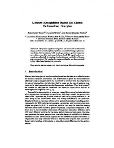
Fig. 1. Smart-Space architecture.
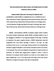
Our process of “Smartification” starts from a generic physical environment, such as a building whose rooms are first uniquely identified (by a barcode, or an RFID tag). To perform the “Smartification” process, each item of interest in the physical environment is first univocally identified and associated to the room in which it is located. This action creates the digital copy of the item in the SS. Further item characteristics may then be added and are available to the SS at any time. For example the smart objects described in the following sections may discover item typology or its status, i.e. if it is working or not, which are exchanged with the SS. The representation of this knowledge is carried out by means of an ontology which is described in Fig. 2: • the digital representation of the object is created as an instance of the Object class (Object_UUID) coupled with an instance of the IdentificationData class, which has the value of the associated RFID tag. • The digital representation of the environment is created as an instance of the Environment class (Room_UUID) coupled with an instance of the IdentificationData class, which has the value of the associated RFID tag. • To achieve the Smartification process the user has to read the room and the object identifiers. The connection between them is created by means of the ContainsEntity property, which connects the room and the object
SYSTEM MIDDLEWARE
Smart environments support dynamic and context-aware applications where artificial entities may collaborate and adapt to the user needs with minimal visibility or impact on user’s life. As a requisite, it is necessary to dispose of a Context Management System (CMS) accessible by all the relevant interacting entities in order to know their context and behave in the most appropriate way. The work described herein is based on Smart M3 [6], the interoperability platform that is under development in the SOFIA European project. The interoperability at information level is carried out by the Semantic Information Broker (SIB) and is provided by the adoption of machine readable technologies for data representation. In particular, the Resource Description Framework (RDF) triple is used as the elementary piece of information in which the subject and the predicate are represented by unique identifiers (URI), while the object may be a URI or a literal value. The use of ontologies specify the domain of interest by means of a representation of the knowledge Figure 1 shows the SS architecture and its connected components: • legacy adapter knowledge processor (KP) is a software program which inserts into the SS all information relevant to the legacy device considered • a consumer KP is a software program which queries, subscribes and inserts into the SS high level information starting from the previously inserted one.
Fig. 2. The “Smartification” process.
III.
ENABLING TECHNOLOGIES FOR THE AUTOMATIC DEVELOPMENT OF A SMART SPACE
Technological objects to assist the user in creating and updating a SS need to be highly effective and reliable but at the same time easy to interact with the user. This is accomplished by augmenting the RFID technology with A) direction finding monopulse radar, to remotely discover and select items (RID) [7]; B) gesture recognizer (GOR), to enable the user to interact with the Smart Space and the devices in a natural way; C) computer vision based item recognizer
522
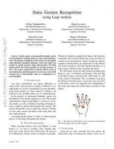
(VOR), to allow items themselves to act as natural tags. These technologies may be adopted, alternatively or simultaneously, to fulfill information exchanges required by the facility management of large buildings described above. This is schematically depicted in fig. 3 where the smart objects ability of perceiving information, such as the item ID, its status and its image, are considered with respect to user-item relative locations (distance and visibility). Intersections between an information level and a smartifier mean that this level of information is made available to the SS. The map clearly demonstrates that joining together these technologies in a smartifier can provide full coverage of the SS needs for this class of applications. The operating principle and preliminary results of these smart objects are described in the following.
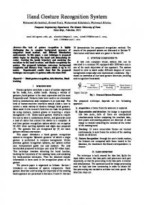
The user starts the interaction with a tagged item by pointing to it: in this way all the tagged items located in close proximity are turned on. The Σ and ∆ transceivers start sending NTX-replica of identical RF signal: the received signal strength indicators (RSSI) are then stored at the tags side. Once the acquisition frame is completed the Σ transceiver, acting as the master, starts to collect back the same data from each tag. From the pointed direction a narrow rotation is performed to resolve the correct ID reception. (a)
(b)
dual-element 2.45 GHz antenna in-phase ports
rat-race coupler Σ − port
item type I n f o r m a t i o n
visible untagged
hidden/visible tagged
∆ − port
2.45 GHz Transceivers
2.45 GHz Transceivers
MSP430
MSP430
Button LEDS
discovery status image
V O R
G O R
R I D
Fig. 4. RID block diagram (a) and prototype (b).
Two RSSIs databases are then available, providing a location map of the objects available in the proximity of the wanted one. A straightforward application of the amplitude comparison monopulse technique (MPR) allows the selection of the wanted ID. To overcome selection and detection errors, which occur in complex indoor environments, a post processing algorithm is carried out based on the knowledge of the tracking orientation at the beginning of the scanning process. For this purpose a window centred around the initial tracking direction is considered and the ID associated with the absolute MPR peak closest to the window centre, rather than highest one, is finally chosen by the SO. Selection/detection time frames are functions of the number of tagged objects and of the number of RSSI acquisitions. The latter may be tuned, at the firmware level, depending on the objects spacing and on the complexity of the ambient. The SO operations are made possible by means of the synergies of the MSP430 firmware of the three involved actors: the active tag at the object side the Σ and ∆ tags at the SO side. Fig. 5 describes the interaction of these actors in the current implementation, which has been used as a test prototype. The measure is started at the PDA by driving initializations of Σ− and ∆− tags peripherals and transceivers. The Σ processor, acting as the master of the entire operation, sends a “wake up” message to the active tags (for the present implementation this is done every 4.6 ms for 1.5 s). On the objects side each active tag switches on every 1 sec and listens for 10 ms the command to activate its transceiver for reception; this process is independent from the Σ−processor temporization. If the “wake up” is received, the active tags are settled in receiving mode. After a 1.5 sec period they are all turned on and the Σ−processor is enabled to
ID short/medium distance
short distance
long distance
user/item distance Fig. 3. Smartifiers operation map.
A. RF-ID enabled remotely identifying and discovering (RID) objects by EM interference A smart object, based on the monopulse radar operating principle, which simultaneously combines maximum and null radiation pattern data of an antenna array [7], is used to remotely select or detect fixed tagged objects, equipped with some intelligence to be exchanged and updated several times for several purposes. The SO operates wirelessly at 2.45 GHz. Its building blocks and a first prototype are shown in Fig. 4. It consists of a two-patch antenna array whose ports are connected to the in-phase port of a rat-race coupler. The coupler Σ and ∆ outputs are matched to two identical low-cost 2.45 GHz transceivers (TI CC2500). Data processing is performed at the same ports by two TI MSP430 processors connected to the transceivers. Similar transceivers are used at the objects side as active tags. They are enabled to interact with the SO by the SO itself using radio-frequency scanning. Two main operations are possible: 1) to select a tagged item and send its identification and characteristics to the SS for subsequent usage; 2) to locate the item selected by another user (e.g. for maintenance applications), update the object’s intelligence with new characteristics to be sent again to the SS.
523
acquire their ID’s. The object selection is then set up and the SO is able to retrieve further data (e.g. last test, faulty, etc.) from the addressed tagged object and to exchange them with the SS. A first test scenario is shown in Fig. 6: it is an office room in which four typical artifacts, placed at a minimum relative distance 50 cm, are equipped with tags. The DIR is intended to interact with the artifact attached to tag #2. PDA
Σ tag start measure
0.5 s
objects tags
∆ tag
initializing and radio wake- up
B. Short range RFID gestural recognizer In this section we present a smart object provided with an RFID reader and a gesture recognizer (GOR). This device enables the user to interact with the SS and devices which have RFID tags gs or appropriate adapters. After reading the RFID tag of an object or a smart device, GOR can interact with its digital properties, stored in the SS, and can send commands or information to the Smart Space. The prototype, shown in Fig. 8 along with its building block diagram, iss composed of three main blocks: the RFID reader, the gesture recognizer and the control unit. In addition, it has a vibro motor and three LEDs to provide feedback to the user. The RFID reader is used to identify the item to interact with. The gesture recognizer has a 3-axis 3 accelerometer and an embedded microcontroller capable to process acquired data. This microcontroller implements a fixed point gesture recognition algorithm, based on Hidden Markov Models [8]. It is capable to recognize a limited set of gestures, such as changes in orientation, continuous rotations of the device around a horizontal axis, or directional movements (e.g. up, right, left). The control unit is a Gumsitx Verdex Verd Pro board [9], it has a Wi-Fi Fi module to communicate with the SS and implements the main KP.
radio ON
initializing and radio wake- up
command: wake up
set RX mode
1.5 s command: send your name active tags name measure and store Σ and ∆ RSSI
Σ burst command: measure + burst
2s RSSI vectors transmission
∆ burst
RSSI vectors transmission store Σ and ∆ RSSI vectors
Fig. 5 Activity diagram of the RID.
to the initial position while sending bursts from its Σ and ∆ ports, according to the timing of Fig. 5. The computed MPR is plotted in Fig. 7: successful selection is obtained by choosing the best centered absolute maximum, which corresponds to tag #2.
2 4
3 1
Fig. 8 Gestural recognizer prototype and block diagram
Considering the Smartifiers described in this work, work the GOR has an intermediate position. It can read unique identifiers from RFID tags, but only from a short distance of a few centimeters. Then it can retrieve or modify status information of the selected object, stored in the SS. In order to employ this SO, wee need to place RFID tags on the desired objects and in the rooms we want to identify as their location. To smartify an environment by using GOR we proceed as follows: first the user adds a room instance in the SS, by performing the corresponding gesture and a then reading the tag identifying the room. In a similar way the user can add an object to the SS, by reading its tag and performing the addObject gesture. Now to enhance the information in the SS the user can add location information placing an object into i a room: for this purpose the user selects the smartification command executing the appropriate gesture and then reads in sequence a room and an object tags. Figure 9 represents a detailed sequence diagram of the interactions between the Smartification involved actors: after the selection of the application, with the corresponding
Fig. 6 Test scenario for the RID proptotype.
Normalized MPR
0 -10
#1 #2 #3 #4
-20 -30 -40 -50 -60 0
50
100
150
200
250
N° of bursts
Fig. 7 RID acquisition performnce.
524
gesture, the user selects a desired object, reading its RFID tag. If it is not already in the CMS, then its digital representation is created, as an instance of the Object class coupled with an instance of the IdentificationData class, which has the value of the RFID tag, as is illustrated in Fig. 2. To create positional information, the user can identify a room by reading the corresponding RFID tag and performing the addRoom gesture. This is equivalent to create an instance of the Environment class and to associate to this an instance of the IdentificationData class (Identification_UUID), which has the value of the room RFID tag. To locate the object into the room, the user reads the room and the object identifiers and executes the addObjectToRoom gesture; this association is created by means of the ContainsEntity property, which connects the room and the object.
order to retrieve the specific object instance from the Smart Space. Instead of RFID, 2D barcodes are used as identification technology. In particular we use Quick Response (QR) codes, which are widely adopted 2D barcodes. QR codes can be scanned at a high speed and can store up to 2.953 bytes; the actual storage capacity depends on the size of the code and on the error correction level, but it is large enough to encode the identifiers associated to the smartified entity in the form of alphanumeric strings. With respect to the operation map in fig. 3 this Smartifier has short identification distance but the quantity of perceived information is higher since we can also detect the ItemModelType of an object. Also the smartification process is quite fast, since the object recognition algorithm takes around 1-2 seconds, depending on the type of object, while decoding of QR codes is almost instantaneous. The system is based on the architecture of the Mobile Visual Search engine [10] shown in fig. 10. It is composed of a mobile device equipped with on-board camera and touch screen (e.g. a smartphone), a Map Server, an Image Processing Server and a remote storing device called Image Store, wherein the pictures to be analyzed are temporary stored. Since the processing capabilities of mobile devices are limited, image analysis is carried out by the remote Image Processing Server. This server contains a database of recognizable models which is loaded during an offline initialization step.
Fig. 9: Activity diagram of a smartification action as executed by a GOR user
C. Object recognition and identification for environment digitalization and hyperlinking The Smartifiers described in the previous sections are all based on the RFID technology. In this section we introduce a Computer Vision based Smartifier, which uses Visual Object Recognition (VOR) and graphical tags to implement an alternative solution to RFID based Smartifiers. The advantage of VOR over RFID or other tag-based identifiers, is that it does not require the user to manually instrument the environment by adding tags, since objects themselves act as natural tags. The main drawback is that the information it provides does not identify the actual instance of an object but rather its model (represented by the ontology class “ItemModelType”). However VOR can be useful in the context of Object Hyperlinking i.e. linking real world objects and locations to relevant information stored in the Smart Space, generally in the form of URLs. In this scenario, indeed, it is not important the instance, but the model (e.g. when information on how to repair a certain type of device is needed). Alternatively, VOR can be combined together with other sensor information (e.g. location and orientation) in
Fig. 10 Visual Smartifier Architecture.
Each time the user takes a picture of an object or of a QR code, the mobile device stores the picture in the Image Store and then inserts a new instance of the ontology class ImageData into the Smart Space. The Image Processing Server is notified by the SIB that there is a new image to be analyzed. The server processes the image and inserts into the SIB the ItemModelType or the decoded string (in the case of QR codes). The Map Server stores the maps of the building floors. The user can download the map of the current floor in his mobile device, modify it and then synchronize all the modifications to the server. The idea behind the Visual Smartifier is that each floor of the building is already identified inside the Smart Space and the
525
In addition to smartification, this device offers functionalities to support the maintenance process. The operator can retrieve his current location by taking a picture of the nearest item or room QR code. He can also ask for the shortest path from its current location to a given item or location. Another useful feature is Object Hyperlinking. Each instance of ItemModelType represents a recognizable object which can be linked to a RelatedInfo instance that ties the item to relevant information. When the maintenance operator requires some technical information regarding a particular type of object, she/he can take a picture of the item and a list of available information is displayed.
corresponding QR code is placed in a suitable location such as close to the elevator or the main stairs. Also an association between the floor ID and the link to the corresponding map in the server is stored within the SIB. When the user wishes to download the map of a floor to start or continue smartification of the floor, he takes a picture of the QR code and then the device retrieves the URL of the related map from the Smart Space and downloads it.
IV.
CONCLUSIONS
We have described a set of smartifiers consisting of highly heterogeneous technologies to be suitably integrated together and with RFID capabilities. They have demonstrated to allow fast and natural operations to automatically set up and update digital representation of physical spaces. Their operating principles and timings are considered for the specific case of the automatic management of the facility maintenance of large complex building, both domestic and industrial. The main features of the middleware to ensure automatic cooperation among these technologies are also accounted for.
Fig. 11 VOR activity diagram
REFERENCES [1] [2]
http://www.theinternetofthings.eu/. D. Manzaroli; L. Roffia; T. Salmon Cinotti; E. Ovaska; P. Azzoni; V. Nannini; S. Mattarozzi; “Smart-M3 and OSGi: The interoperability platform” IEEE ISCC, p.1053-1058, June 2010. [3] http://sofia-project.org/ [4] A. D'Elia, L. Roffia, G. Zamagni, F. Vergari, P. Bellavista, A.Toninelli, S. Mattarozzi, “Smart applications for the maintenance of large buildings: How to achieve ontology-based interoperability at the information level” IEEE ISCC, p.1077-1082, June 2010. [5] S. Bartolini, L.Roffia, T. Salmon Cinotti, D. Manzaroli, F. Spadini, A. D’Elia, F. Vergari, G. Zamagni, L. Di Stefano, A. Franchi, E. Farella, P. Zappi, A. Costanzo, E. Montanari “Creazione automatica di ambienti intelligenti”. Patent Pending. March 2010, BO201A000117. [6] J. Honkola. (2010, December 30). Smart-M3 public source code [Online]. Available: http://sourceforge.net/projects/smart-m3/ [7] A. Costanzo, D. Masotti, S. Bartolini,T. Salmon Cinotti, E. Montanari and N. Arbizzani, " Design and test of a smart-space interaction device combining RFID and electromagnetic interferometry”, 2011 IEEE IMS, Baltimore, June 2011. [8] B. Milosevic, E. Farella, L. Benini, “Continuous Gesture Recognition for Resource Constrained Smart Objects”, Int. Conf. on Mobile Ubiquitous Computing, Systems, Services and Technologies (UBICOM), pp.391-396, October 2010. [9] http://www.gumstix.com/store/catalog/product_info.php?products_id=2 10 [10] A. Franchi, L. Di Stefano, T. Salmon Cinotti, "Mobile Visual Search using Smart-M3," Computers and Communications (ISCC), 2010 IEEE Symposium on, pp.1065-1070, 22-25 June 2010 .
Fig. 11 shows a sequence diagram describing the interaction between the various entities during the Smartification process. The user can add new items to the map by simply taking a picture of the physical object. The identification process detects the object in the picture and the corresponding item icon appears in the map (see fig. 12). The user, after placing the item in a room of her/his choice, can confirm the addition. In order to smartify an item or a room, the user has to attach a QR code to the entity and then take a picture of it (fig. 12).
Fig. 12 Visual Smartifier usage example
526