handle the inter-procedural calls. They had used the ... S6: System.out.println(âPRODUCT NUMBER=â+number); ... of the user-defined class will be created and used to call the methods ..... Proceeding of the ACM SIGPLAN'90 Conference on.
International Journal of Computer Applications (0975 – 8887) Volume 80 – No.8, October 2013
Computing Dynamic Slices of Object-Oriented Programs using Dependency Information Swatee Rekha Mohanty
Prafulla Kumar Behera
Durga Prasad Mohapatra
Department of Computer science, Rourkela Institute of Management Studies, Rourkela, India
Department of Computer Science and Application, Utkal University, Vani Vihar, Bhubneswar, India
Department of Computer science and Engg., National Institute of Technology, Rourkela, India
ABSTRACT Now a days, object-oriented programs are becoming very popular amongst the developers and hence almost all software are designed using the object-oriented paradigm. Advanced features of object-oriented programming has made it complicated to understand, test, debug and maintain. To better manage these software, slicing techniques have been proved to be quite efficient. This paper proposed an algorithm for dynamic slicing of object-oriented software. It uses SDG(System Dependence Graph) and DG(Dynamic Graph) as the intermediate program representation while computing the dynamic slices. In this paper dynamic slicing algorithm is based on traversing through the outgoing control dependence edges and incoming data dependence edges of Dynamic Graph. The major advantage of the proposed algorithm is that the time required to compute the dynamic slice of the objectoriented programs is directly proportional to the number of dependencies (control and/or data) arising during the run time. Also the proposed algorithm depends on the numbers of nodes present in the intermediate program representation.
GENERAL TERM Program analysis, Dynamic slice, Object-oriented programs.
KEYWORDS Program Slice, Dynamic Slice, System Dependence Graph, Class Dependence Graph, Dynamic Graph.
1. INTRODUCTION Software is playing a crucial role in our day to day transactions. It is very much associated with the hardware and it enables a system to work properly. Each day we are coming across several software directly or indirectly. Software were evolved with their basic applications in scientific and mathematical calculations. They were adopting the procedureoriented approach, and were very simple to test, debug and maintain. But to eradicate some problems in procedural languages, object-oriented programming paradigm has come to the existence. The object-oriented languages are enriched with some additional features, such as classes, objects, data abstraction, encapsulation, inheritance, polymorphism, dynamic binding, message passing etc. The main purpose was to treat the data as the most critical element in the software, hence do not let it move freely throughout the system and to visualize the problem in terms of entity instead of focusing on the procedures. Due to these features, object-oriented software became bit complicated to test, debug and maintain. Now a days almost all software are adopting the object-oriented features. They are complicated as well as lengthy. Hence it is
a challenge in front of the software developers to test, debug and maintain those software. Slicing is a technique that has its application in software understanding, testing, debugging, maintenance, reverse engineering etc. It was a concept developed by Mark Weiser[2] in the year 1979. According to Weiser[2], a slice of a program P with respect to a slicing criterion is the set of all statements of the program P that affect the slicing criterion for any possible input to the program. This slice was named as static slice and it was not precise, because Wiser had computed the slice without considering the possible input to the program. Hence the computed slice may contain some statements which may not be executed for an actual run of the program. From this, it is very clear that the slice should be statement minimal i.e. it should contain those statements which actually affect the variable var computed at the slicing criterion. In this context, it is realized that the dynamic slice will be much effective, as it is computed taking into consideration the input to a program. It is precise and it contains those statements which actually affect the variables at the slicing criterion for a specific input to the program. Dynamic slicing concept was first introduced by Korel and Laski[3], who computed the slice corresponding to an actual run of a program. Dynamic slice was found to be useful in various software engineering activities such as program understanding, debugging, testing, software maintenance etc. Before computing the dynamic slice of a program, this paper represent the object-oriented program using an intermediate program representation. To represent the intra-procedural programs, PDG (Procedure Dependence Graph) is useful[11]. To represent inter-procedural programs SDG (System Dependence Graph) is useful[12]. But these two representations are not suitable to represent the objectoriented programs. So, this paper uses the ClDG (Class Dependence Graph) proposed by Larsan and Harrold [13] for representing the object-oriented programs. A dynamic slice can be computed by applying the slicing algorithm on the intermediate program representation. It has been found in the literature that researchers have emphasized on developing the algorithm in terms of less time complexity and space complexity. This paper proposed an efficient algorithm to compute the dynamic slices of object-oriented programs. This paper developed an algorithm to compute the dynamic slices of object-oriented programs. Before implementing the algorithm, it created a suitable system dependence graph to represent object-oriented programs. Then, it created a dynamic graph out of the system dependence graph which
1
International Journal of Computer Applications (0975 – 8887) Volume 80 – No.8, October 2013 represents the data and control dependencies between the actual executable statements of the program. The algorithm computes precise dynamic slices of object- oriented programs by traversing the dynamic graph through the outgoing control dependence edges and incoming data dependence edges. The rest of the paper is organized as follows: Section 2 contain review the available related work. This paper present some basic concepts and definitions in Section 3. Section 4, contain proposed algorithm. Section 5 implements the proposed algorithm. The work is compared with the existing ones in Section 6. In Section 7 present conclusion and future work.
2. REVIEW OF RELATED WORK Weiser[2] introduced the concept of static program slice for intra-procedural programs. He used CFG(Control Flow Graph) as the intermediate representation of the program. His approach was based on solving the data flow equations iteratively. But his approach was not able to handle the interprocedural programs i.e. programs having multiple procedures. To overcome this problem Weiser[2] developed a two-phase interprocedural static slicing algorithm. Ottenstein and Ottenstein[11] introduced PDG (Program Dependence Graph) to represent the intra-pocedural programs while computing static slices. They have performed the graph reachability analysis using PDG. But their approach was not able to compute the dynamic slices of inter-procedural programs. Horwitz et al[12]. extended the representation proposed by Ottenstein and Ottenstein[11] to construct SDG(System Dependence Graph), which was capable of representing the inter-procedural programs efficiently. Korel and Laski[3] introduced an algorithm to compute the dynamic slices of inter-procedural programs. They had extended the approach proposed by Weiser[2] to compute the static slices of intra-procedural programs. Korel and Laski[3] computed dynamic slices of inter-procedural program by solving the data flow equations. Korel and Laski needed O(N) space to store the execution history and O(N2) to store the dynamic flow of data, where N is the number of statements executed. It may be noted that the, in case of loop control structure, N may be unbounded. The dynamic slice computed by Korel and Laski may be imprecise, that means it may contain some of the statements which do not affect the value computed at the slicing criterion. Agrawal and Horgan[6] proposed an algorithm for computing the dynamic slices of programs using the dependence graph. Then, many researchers had proposed algorithms for computing the dynamic slices of programs. But many of them found to be imprecise. To compute precise dynamic slice, Agrawal and Horgan[6] introduced the DDG(Dynamic Dependence Graph) which can be constructed by using the PDG(Program Dependence Graph). But, The DDG of a program can be computed by creating a new node for each occurrence of a statement along with its associated control and data dependence edges. The major disadvantage of this approach was that the number of nodes in the DDG may be unbounded for programs having loops. Agrawal and Horgan[6] modified their approach by introducing RDDG(Reduced Dynamic Dependence Graph). They tried to reduce the number of nodes in the DDG by
including a node if and only if it can create a new dynamic slice. Mund et al[10] taken MPDG (Modified Program Dependence Graph) as intermediate program representation. They had used the concept of stable and unstable edges. They had proposed an edge-marking algorithm where they marked and unmarked the unstable edges of MPDG when a dependence arise and cease during the execution time. Mund et al.[9] proposed another algorithm for computing intra-procedural dynamic slices. They had used PDG as the intermediate program representation. The space complexity of their algorithm is quadratic in the number of statements in the program, and the time complexity of their algorithm was O(n2), where n was the number of the statements in the program. Mund and Mall[10] proposed an efficient inter-procedural dynamic slicing algorithm for structured programs. They proposed an intra-procedural algorithm for computing dynamic slices of structured programs and then extend it to handle the inter-procedural calls. They had used the CFG(Control Flow Graph) as the intermediate representation of the program. They explained that their dynamic slicing algorithm was efficient than the existing dynamic slicing algorithms. Larsen and Harrold [13] had proposed the construction of SDG(System Dependence Graph) for computing interprocedural dynamic slice of object-oriented programs. They had correctly represented all the features of object-oriented programs in the SDG. The major advantages of their approach was that the SDG can be constructed incrementally because representation of the classes can be reused. Another advantage of their approach is that the slices can be computed for incomplete programs such as classes or class libraries. Their slicing algorithm consisting of two passes. The first pass traverses backward along all edges except parameter-out edges and marks those vertices reached. The second pass traverses backward from all vertices marked during the first pass along all edges except parameter-in edges and marks the reached vertices. They had computed the dynamic slices as the union of vertices marked during pass one and pass two.
3.
BASIC CONCEPTS AND DEFINITIONS
This section focuses on two major aspects: first on description of the intermediate representation needed to represent an object-oriented program, and second on description of the various basic concepts and definitions used in our algorithm.
3.1 Intermediate representation of objectoriented programs A suitable intermediate representation of the program is needed to compute precise dynamic slices. For the representation of OOPs, This paper uses SDG (System Dependence Graph) and DG (Dynamic Graph).
3.1.1.
System Dependence Graph(SDG)
Ferrante et al. proposed Program Dependence Graph(PDG) to represent the intra-procedural programs. But it was not suitable to represent the programs having multiple procedures. Horwitz et al.[12] proposed System Dependence Graph (SDG) to represent the inter-procedural programs. Larsen and Harrold[13] extended the System Dependence Graph to represent the features of object-oriented programs. This paper uses the representation of Larsen and Harrold [13] with little
2
International Journal of Computer Applications (0975 – 8887) Volume 80 – No.8, October 2013 modification. Let us consider the example program given in Figure 1. import java.lang.*; CE1: Class Product { int number; float cost; public: ME2: void getdata(int a, float b) { S3: number=a; S4: cost=b; } ME5: void putdata() { S6: System.out.println(“PRODUCT NUMBER=”+number); S7: System.out.println(“PRODUCT COST=”+cost); } } MCE8: class Example { MME9: public static void main(String args[]) { S10: Product p1=new Product(); S11: p1.getdata(100,299.95); S12: p1.putdata(); S13: Product p2=new Product(); S14: p2.getdata(200,175.50); S15: p2.putdata(); } } Figure 1: An example program
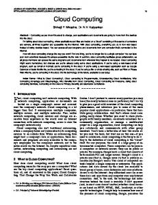
Representation of a class This paper taken ClDG to represent the class defined in the example program. A class is basically a combination of data and methods. Using the ClDG the data and control dependencies can be represented within the class. Each method of a class is represented by the procedure dependence graph. Each method has a method entry vertex which describes the entry to that method. Each class is having a class entry vertex. There is an edge between the class entry vertex and the class members (i.e. data or methods). That edge is known as class member edge. Figure 2 shows the ClDG of the class product in the example program of Figure 1.
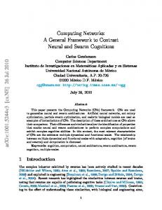
Larson and Harrold[13] had constructed the SDG of a complete object-oriented program by connecting the procedure dependence graphs of main method to methods in the ClDG. This paper done little bit modification in the representation as the example program is in Java instead of C++. The representation of Larson and Harrold is best suited to the programs written in C++. The example program have two ClDGs. One for the user defined class and another for the main class where the objects of the user-defined class will be created and used to call the methods of the respective classes. Figure 3 describes the class dependence graph (ClDG) for the main class of in the Example program given in Figure 1.
Figure 3: ClDG of the main class given in Figure 1
Representation of the complete program The ClDGs of the user-defined class and the main class in the example program (in Figure 1) are shown in Figure 2 and 3, respectively. But, both are incomplete until unless there is some connection between the call vertex in the main class and the method entry vertex in the user-defined class. Figure 4 represents the complete intermediate representation of the example program given in Figure 1. This paper referred the intermediate representation of Larsen and Harrold[13]. They have constructed intermediate representation for the C++ programs. This paper extends the representation of Larsen and Harrold[13] to handle Java programs. The basic difference is that, as Java is a pure object-oriented programming language, this paper constructs an intermediate representation by considering two types of ClDGs (Class Dependence Graph). One for representing the user-defined class and another for the main class where objects for the user-defined class will be created. That means, this paper not taken PDG(Procedure Dependence Graph) to represent the main method. After constructing the individual ClDGs, the procedure call vertex joined with its respective procedure by means of a control dependence edge.
Figure2: ClDG of the example program given in Figure 1
3
International Journal of Computer Applications (0975 – 8887) Volume 80 – No.8, October 2013
3.2. Basic concepts and definitions used in our algorith This section, explain the basic concepts and definition used in our algorithm.
3.2.1 Control Dependence Let x and y are the two different nodes in a system dependence graph. Node y depends on node x if there is a directed path \from x to y, indicating that execution of y depends on execution of x. Then, node y is said to be control dependent on node x.
3.2.2.Data dependence Let x and y are two different nodes in a system dependence graph, then node y is data dependence on node x, if a variable var defined at x is used at y. There exists a directed path exist from x to y.
3.2.3 Def(var) Let var be a variable in a program P. Then a node u is said to be Def(var)node, if u defines variable var.
3.2.4 Use(var) Let var be a variable of the program P. Then a node u is said to be Use(var) node, if u uses the value of the variable.
3.2.5 DefVarSet(u) After constructing the SDG of the example program its Dynamic Graph can be constructed as follows.
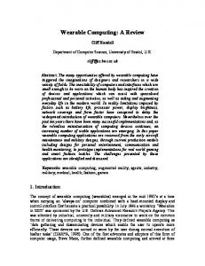
3.1.2.Dynamic Graph(DG): After constructing the SDG of the program, this paper construct the Dynamic Graph of the program. Purpose of constructing the DG is that, to consider only the control dependencies and data dependencies between the statements, which are actually executed depending on a specific input to the program. In that way, the intermediate representation of the program will be simple to manage during implementation, and will be convenient for traversal to compute the dynamic slices. The Dynamic Graph of the example program is given in Figure 5.
Let var and u be the variable and the node respectively. DefVarSet(u)={var : var is a variable of the program P and u is a Def(var) node}.
3.2.5 UseVarSet(u) Let var be a variable and u be a node then UseVarSet(u)={var: var is a variable of the program P and u is a Use(var) node}. Considering the example program taken in Figure 1, This paper state that S11 is data dependence on S10, S12 is data dependence on S10, S14 is data dependence on S13, S15 is data dependence on S13. S10 to S15 are control dependence on MME9. Def(p1)=S10, Def(p2)=S13. Use(p1)=S11, S12, Use(p2)=S14, S15. DefVarSet(S11)=p1, DefVarSet(S12)=p1, DefVarSet(S14)=p2, DefVarSet(S15)=p2.
3.2.6 ActiveControlSlice
Figure 5: Dynamic Graph of the example program
If s be the test node in the SDG of the program P and UseVarSet(u)={var1, var2, ……, vark}. Before execution of the program P ActiveControlSlice(s)= φ, After each execution of the node s in an actual run of the program, ActiveControlSlice(s)={s} U ActiveDataSlice(var1) U ……U ActiceDataSlice(vark) U ActiveControlSlice(t). Where t is the most recently executed predicate node of s in the SDG.
4
International Journal of Computer Applications (0975 – 8887) Volume 80 – No.8, October 2013 a)
3.2.7 ActiveDataSlice(var) Let var be a variable of the program P. Before execution of the program P ActiveDataSlice(var)= φ. Let u be a Def(var) node and UseVarSet(u)={var1, var2, ……, vark}. Let the program P will run with a given set of input value. After each execution of the node u in the actual run of the program, ActiveDataSlice(var)={u}U ActiveDataSlice(var1) U…………UActiveDatSlice(vark) U ActiveControlSlice(t). Where t is the most recently executed predicate node of s in the SDG.
Compute DyanSlice(u, var)= ActiveDataSlice(var) ActiveDataSlice(var) cab be computed by traversing through the incoming data dependence edges and list the reached nodes. b)
ActiveDataSlice(var) represents the set of nodes that affect the most recently updated value of the variable var. For execution of the node s, the set of nodes on which the execution of s has the direct or indirect control dependence is ActiveDataSlice(t), where t is the most recently executed predicate node of s in the SDG.
ActiveCallSlice(u) can be computed by traversing through the outgoing control dependence edges and incoming data dependence edges and list the reached nodes.
Let s be a node of the program P and var be a variable in the set DefVarSet(s) U UseVarSet(s). Before execution of the program P, DyanSlice(s, var)= φ. Let us run the program with a given set of input value. For each execution of the statement s, DyanSlice(s, var) =ActiveDataSlice(var) U ActiveControlSlicet(t), where t is the most recently executed predicate node of s.
c)
ActiveControlSlice(u) can be computed by traversing through all the control dependence edges and list the reached nodes.
Let ucall be a call node. Then ActiveCallSlice(ucall)=ActiceDataSlice(var) U ActiveControlSlice(ucall), where var is the variable/ object used to call the method. d)
PROPOSED ALGORITHM
Step 1: Consider an object-oriented program P. Step 2: Construct the SDG of the program.
a)For each node u do the If u is a predicate node then ActiveControlSlice(u)= φ For each variable var є DefVarSet(u) U UseVarSet(u), set DyanSlice(u, var)=φ b)For every variable var of the program P, set ActiveDataSlice(var)= φ. c)Set ActiveCallSlice= φ. Step 4: Run the program P with the given set of input value.
If u is a Def(var) and Use(var) node Compute DyanSlice(u, var)=ActiveDataSlice(var) U ActiveControlSlice(t), where t is the most recently executed predicate node.
This section presents algorithm to compute dynamic slice of object-oriented programs.
followings:
If u is a test node Compute DyanSlice(u, var)= ActiveControlSlice(u)
3.2.9 ActiveCallSlice
Step 3: Do the followings before execution of the program
If u is a call node Compute DyanSlice(u, var)= ActiveCallSlice(u)
3.2.8 DyanSlice(s, var)
4.
If u is a Def(var) node and not a call node
Step 7: Exit when execution of the program P terminates.
5.
IMPLEMENTATION OF THE ALGORITHM
This paper implemented the slicing algorithm in Java. and computed slice of several object-oriented programs. The proposed algorithm works efficiently and generates precise slices. The proposed algorithm is not based on traversing the complete SDG rather it works on the Dynamic Graph, which is created using the real executable statements with respect to particular input to the program. Let us consider the program in Figure 1. This paper constructed the system dependence graph of the program as shown in Figure 4. Then, this paper run the program to get the actual executable statements. The data and control dependencies between those statements are represented by the dynamic graph as shown in Figure 5. When the Dynamic Graph is traversed using the proposed algorithm the following updates can be found:
Step 5: Construct the DG(Dynamic Graph) by considering the dependencies(control/data) between the actual executable statements based on the input to the program. Step 6: Computation of the dynamic slice
5
International Journal of Computer Applications (0975 – 8887) Volume 80 – No.8, October 2013 Table 1: Slice computation time of the nodes of Example program 1 No. of Nodes in DG
Type of Node
Slice Node
Slice
Computation Time(in Millis)
13
Def(var)
S10
{ S10}
3.5013
Def(var)
S13
{ S13}
1.0616
Call
S11
{ S10, S11,ME2,S3,S4}
4.5513
Call
S12
{ S10, S12, ME5, S7, S6}
4.7100
Call
S14
{ S13, S14, ME2, S3, S4}
3.4615
{ S13, S15, ME5, S6, S7}
4.6642
Call
To illustrate the example program, Dynamic Graph is a particular node nodes 5, 9, 13.
S15
6.
This paper analyze the work done by Korel and Laski[3] and found the time required to compute the dynamic slice is O(N 2) where N is the numbers of nodes in the program. Major disadvantage of the approach of Agrawal and Horgan[6] is that the numbers of nodes in the DDG(Dynamic Dependence Graph) may be unbounded for program having loops. Hence the time of computation of slice must be increase. Mund et al.[9] proposed algorithm for computing intra-procedural dynamic slice. And the time complexity of their algorithm is O(n2) . Where n is the number of the statements in the program. But the proposed algorithm computes the dynamic slice in such a way that the slice extraction time is directly proportional to the number of edges (control and/or data) of the Dynamic Graph. It does not depend at all on the number of nodes in the intermediate representations.
7.
above point, this paper considered the where the total number of nodes in the 13. This paper computed dynamic slice of say Def(var) node 2 by considering the
COMPARISON WITH RELATED WORK
CONCLUSION AND FUTURE WORK
This paper explained how to construct the Dynamic Graph which will show the control and data dependencies among the real executable statements. The objective was to minimize the time of computation of slice. And also to avoid the complete traversal of the SDG. The proposed algorithm efficiently works on the Dynamic Graph and generate precise slice. This paper observed that the time of computing dynamic slice is not depends on the numbers of nodes in the DG. It depends on the number of edges (control and/or data) exists in the Dynamic Graph. This paper does not consider the concept of polymorphism and Inheritance of object-oriented features. Next, we will be extending our algorithm to compute the dynamic slice of object-oriented programs with those object-oriented features. Along with that in future, we will focus on computing dynamic slices of concurrent object-oriented programs and distributed object-oriented programs.
8.
REFERENCES
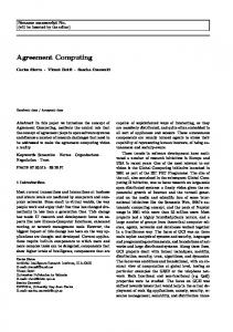
[1] M. Weiser, “Programmers use slices when debugging”, communications of the ACM 25 (7)(1982) 446-452. [2] M. Weiser, “Program Slicing”, IEEE Transactions on Software Engineering 10 (4) (1984). Figure 6: Graph during computation of slice in Def(var) node in S10 example program 1 From the graph it can be clearly observed that, the proposed algorithm takes approximately same time while computing the dynamic slice, even if the numbers of node increases. Time of computing slice is directly proportional to the number of dependencies (control and/or data) The complexity of our algorithm is O(n2) where n is the number of edges (control and/or data) of the program.
[3] B. Korel, J. Laski, “Dynamic program slicing”, Information Processing Letters 29 (3) (1988). [4] J Lyle, “Evaluating variations on program slicing for debugging”, PhD Thesis. [5] M .Karmakar, “Interprocedural dynamic slicing with applications to debugging and testing”. [6] H. Agrawal, J. Horgan, “Dynamic program slicing”, Proceeding of the ACM SIGPLAN’90 Conference on programming Languages Design and Implementation, SIGPLAN Notices, Analysis and Verification, White Plain, New York, vol 25, no. 6, 1990, pp. 246-256. [7] Zhang, X., Gupta, R., Zhang, Y.,2003. “Precise dynamic slicing”. In:Proceeding of the 25th International conference on software Engineering, Porland, Oregan, pp. 319-329.
6
International Journal of Computer Applications (0975 – 8887) Volume 80 – No.8, October 2013 [8] Mund et. al., “An efficient dynamic program slicing technique”, Information and Software Technology 44(2002) 123-132. [9] Mund et. al., “Computation of intra-procedural dynamic program slices”, Information and Software Technology 45(2003) 499-512. [10] Mund et. al., “An efficient inter-procedural dynamic slicing method”, The Journal of Systems and software 79(2006) 791-806. [11] Ottenstein, K., Ottenstein, L.,. “The program Dependence Graph in software development
IJCATM : www.ijcaonline.org
environment”. In: Proceedings of the ACM SIGSOFT/SIGPLAN Software Symposium on Practical Software Development Environments, SIGPLAN Notices, vol. 19(5), pp 177-184(1984). [12] Horwitz , S., Reps, T., Binkley, D., “Interprocedural slicing using dependenc e graphs”. ACM Transactions on Programming Languages and Systems 12(1), 26-61, 1990. [13] Loren Larsen, Mary Jean Harrold, “Slicing Objectoriented Software”, Published in proceeding of ICSE, 1996, PP-495-505.
7