Concept validation of a MEMS powered, automatic multichannel pipetting device Ana L. Quintanar-Meléndez, C. Amnael Orozco-Díaz, Rogelio Bustamante-Bello, José R. ÁlvarezBada, M. Karla Muguerza-Jiménez, and Jessica Nava-Rojas, Microsystems Research and Biodesign Center, Instituto Tecnológico y de Estudios Superiores de Monterrey, Campus Ciudad de México. those found in the former. These devices work through various mechanical components to regulate de amount of sample volume that will be delivered. Due to their nature, however, there are intrinsic disadvantages that call for the introduction of microelectromechanical systems (MEMS) to compensate for in order to automate the preparation processes described above. Due to the very nature of biochemical procedures and their required precision, it is necessary to carry out extensive characterization tests to evaluate the performance of the MEMS devices and compare them to the mechanical actuators of conventional pipettes in order to define their functionality, viability, and operation range. This is an industrial application-oriented development. This project’s main objective is to create a device that, with the use of automation technology, can adequately undertake and enhance the hereby studied process. The result should be a more precise, faster, low-cost and high quality piece of equipment.
Abstract— Small liquid volumes are commonly handled in biological research by means of manual devices or by rather complex automatic systems. Micropipettes, which are the most used devices, require manual operation, which limits their accuracy and may lead to sample contamination if improperly used. Diaphragm micropumps are proposed as an alternative to micropipettes for the liquid-manipulation system reported in this work. The average difference in the delivered volumes is of 0.66 microliters for a total volume of 22 microliters, the difference being attributable to experimental conditions requiring a more precise adjustment. Furthermore, to facilitate the MEMS-based automation process, a functionality analysis of the micropumps was performed in an 8-output circuit. A satisfactory result was obtained, with a more uniform set of volumes obtained in these tests.
Index Terms— fluid delivery, fluid sampling, characterization, diaphragm micropump
I. INTRODUCTION
II. MOTIVATION
T
HE preparation of biomolecular solutions for different instances of qualitative and quantitative conformational analyses in the diverse areas of biological research requires the distribution of small-volume samples in container-matrix arrays of standard sizes. Manual, mostly mechanical devices such as micropipettes are widely used, while automated devices rely on design and operation principles similar to
A. State of the Art The automation proposed in this work has the main goal of reducing the time – and manpower – required for filling the sample container’s matrix arrays with biological solutions in such a way as to reduce the monetary cost of the procedure and aiming towards a minimization in the long run. There are similar existing technologies that seek to achieve this goal but they carry out many other lab protocols and applications, integrating several high-technology applications onto an excessively complex product which, occasionally, leads to an important underutilization of the technologies. The manual instruments currently used – micropipettes – rely almost entirely on mechanical principles for their operation – although some more expensive models integrate electronic regulation for volume delivery [1]. Due to this fact, they can experience mechanical deviations such as friction and wearing-off of components that worsen their precise functionality. As these instruments are manually operated, there are also some slight variations between samples due to human error. The automation here proposed will deal with both issues. MEMS elements were chosen to replace mechanical actuators to achieve this aim because of their intrinsic calibration reliability, reduced temperature drift, and convenient size, all of which allows for an efficient performance and a reduced usage of space and power supply.
This work was supported by the Instituto Tecnológico y de Estudios Superiores de Monterrey - Mexico City Campus. Ana L. Quintanar-Meléndez is now research assistant at the Research Center on Microsystems and Biodesign, Instituto Tecnológico y de Estudios Superiores de Monterrey - Mexico City Campus, Mexico City, 14390, Mexico. She was research assistant at the National Institute of Genomic Medicine, Mexico City, 01900, Mexico (e-mail:
[email protected]). C. Amnael Orozco-Díaz is now research assistant at the Research Center on Microsystems and Biodesign, Instituto Tecnológico y de Estudios Superiores de Monterrey - Mexico City Campus, Mexico City, 14390, Mexico. (e-mail:
[email protected]). Rogelio Bustamante-Bello is Head of the Research Center on Microsystems and Biodesign at the Department of Mechanics and Electronics Engineering, Instituto Tecnológico y de Estudios Superiores de Monterrey - Mexico City Campus, Mexico City, 14390, Mexico (phone: (+52)(+55)54832202). José R. Álvarez-Bada is working with the Research Center on Microsystems and Biodesign, Instituto Tecnológico y de Estudios Superiores de Monterrey Mexico City Campus, Mexico City, 14390 Karla Muguerza-Jiménez is currently working at the Program Managment Department in Chrysler de México, Mexico City, 05109, Mexico. Jessica Nava-Rojas is currently working at the Product Engineer Department at Chrysler de México, Mexico City, 05109, Mexico.
978-1-4244-4480-9/09/$25.00 ©2009 IEEE
325
B. Both versions utilized Eppendo orf® 10-20 µl micropipette disposable tips at their outputs.
As main MEMS actuator diaphragm micro pumps were module). Previous chosen [2] (two of them for the actuation m analyses [3] with these components show wed that, for an approximate actuation signal frequency of 110 Hz and a duty cycle of 70/30, the used micropumps show a linear dependence of the expelled volume with timee.
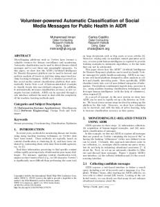
Figure 1a represents the coupling g utilized for a single-exit tests of the microactuator system. Further discussion on this first approach is presented on the results section below. For the single-output system, an activaation voltage train for the actuators of 85 Hz was employed as well as a suction time of 4 seconds an expulsion time of 12 seconds. t microactuator system The intended application for the demands an eight-output array. This T design is graphically represented in Figure 1b. In order to handle the new load of the system without varying the sucttion and expulsion times, a frequency of 110 Hz for the activ vation voltage train of the actuators was selected to compensaate for the new load of the circuit.
B. Objectives mplementation of The proof of concept in regards of the im MEMS devices for suction and ejection of lliquids through a bidirectional fluidic and pipetting automationn system was the main goal of this work. This actuation modulle, however, must be housed in a complete system that alllows for a full automation of the process described in the Introduction section. It is also very important to have a quantitative and trustworthy concept-validation protocol in orrder to be able to evaluate the amount of volume sampled in each of the matrix’s cells during the tests and to comparre their mass and volume with those parameters obtained frrom the samples using manual micropipettes as a control refereence. III. METHODOLOGY A. Protocols In order to carry out the tests for charactterization, it was necessary to develop a protocol to be follow wed and to reduce possible variations in the results due to thhe methodology. Among those variables evaluated in the tessting process, we should mention the volumes delivered by thhe microactuators, which were compared to those from a commercial micropipette (a brand-new Eppendorff® 10-100 µl monochannel micropipette with its retail calibration seal untouched). Intended volume delivery settingg for both devices was set to 20 µl. Such amounts were analyzedd in terms of their weight, volume and environmental evaporatiion factor, which depend on the environmental pressuure and other environmental conditions. For the testingg stage, a fourdecimal-digit analytical balance AB265-S S from Mettler Toledo Inc. was used. As a base for the elaboration of the protocol to be utilized in the testing, the compparatively similar Eppendorf® and Rainin® micropipette callibration manuals were consulted [4], [5]. After the determ mination of the evaporation rate in the laboratory environm ment [5], it was necessary to take at least 10 fluid samples inn order to validate a test, evaluate their weight and obtain an avverage weight and standard deviation. The average delivereed volume was determined from equation (1).
V = (w + e ) ⋅ Z
Fig. 1. Schematic representation of (a) the constructed circuit for one output and (b) the constructed circuit for eight outpu uts.
IV. RESUL LTS The following results from the critical testing stages are discussed in this section: compariison of the microactuator versus micropipette performancess, and the performance evaluation of the eight-output systeem. The same Eppendorf® pipette with 200 µl disposable tips and a laboratory-grade water were used for all single-output tests. A. Performance comparison of miccroactuators and micropipettes For the single-output system, the protocol described in the oyed. Two sets of 17 methodology section was emplo independent samples were evaluateed for this phase; one set corresponds to the microactuator sy ystem, and the other one to the micropipette.. Figure 2 provides a graphical comparison of the output volumes.
(1)
In (1), w was the average weight of the saample, e was the evaporation factor and the Z-factor was caalculated, for the experimental site’s altitude and environmentaal pressure, to be equal to 1.003102 [4], [5]. The average voluume in each of the tests was determined to be the average of every prior measurement of that same test [4], [5].
326
D. Process protocol considerations This project is intended to widen the use of automated devices which work only with non-biologic substances by designing it to work with biological, genetic and abiotic solutions indistinctively. To accomplish this objective, special considerations must be taken: 1. Materials, such as tips and well-plates, must remain in a sterile environment before being used, and must not interact physically or chemically with the substances they host. 2. Each tip must only be used for one cycle which includes: one suction and one ejection of the solution. 3. To fill the tips with the solution, these must remain at least 3 seconds submerged into the solution before taking in the sample; this action is intended to avoid turbulence generated by the introduction of the tip to the media[4], [5]. 4. After obtaining the sample and lifting the tips, they must be left steady at least 3 seconds to eliminate solution residues on the external part of the tip. 5. Transportation of tips carrying samples must be smooth and at a low acceleration rates to prevent the solution from mixing in case of abiotic solutions and recombining or denaturalizing in case of biological solutions. 6. Used tips must be safely disposed to avoid possible contamination.
B. Eight-output system performance evaluation For a simplified analysis of this system, samples for outputs numbered 4 and 6 were measured. For this test, 10 samples were simultaneously taken out of each of the outputs; their measurements were weighted together. Figure 3 displays the results of this analysis. Optimized connections and their safer securing can account for the more stable results, although a degree of variation was still present. Another determining factor could be that the output resistance of the system is lowered by the addition of parallel outputs, thus reducing the backpressure on the actuators.
V. SYSTEM OVERVIEW In order to have a better understanding of the system, the operation of the systems must be described. This may be divided into three main groups: Base Plate Preparation, Volume Selection and Filling Cycle. A. Base Plate Preparation: A base plate with the proper geometry and distribution was designed for this project. Its main objectives are to optimize the sampling cycle time by designing a horizontal distribution of the system components to avoid redundant movements. Also, its objective is to establish a single, vertical level of the system’s components in order to reduce the number of vertical positions the mobile components must assume, as shown in Figure 4. The procedure for the usage of the equipment should be the following:
C. Design restrictions for the full system This project was designed according to five major constraints that define its scope: 1. Portability: commercial automated sampling devices [2] are very large and are essentially stationary; this project is restricted to occupy the least volume possible (in the scale of a tabletop piece of equipment) and to be self-contained. 2. Standard material and components: automated equipments use integrated tubing, disposable tips to manipulate solutions or sample. [6]. These tips are designed and manufactured by each of the equipment suppliers.
1. A new tip- rack must be placed in the first base plate’s position. 2. The solution must be poured into a proper container and placed in the second base plate’s location. This container has a cover with the adequate number of pipette-tip entry holes to avoid sample contamination. 3. A ready-to-use well-plate must be placed in the third base plate’s position. 4. The tip-disposal container is to be located in the fourth position and must be emptied at the end of the filling cycle.
In order to comply with standard protocols, this project requires the use of standard, disposable Rainin® pipette tips. 1. Capability: this system has to be capable of handling the same volume ranges as manual and automated systems (using pipette tips of various sizes in the 1 to 1000µl interval) [3]. 2. Distinctiveness: the core of the project is the use of MEMS (Micro ElectroMechanical Systems).
327
hrough thermal isolation, need of heat-transfer handling th active refrigeration or other adequate means. As the device is projected to have laboratory person nnel as end users, a simple and comprehensive user interface fo or the programming of the device’s operation, calibration and d operation tests is to be developed as well. The use of dispo osable pipette tips calls for the evaluation of the device’s perfo ormance using filtered tips, which will pose a different – most likely, higher – resistance put, for which specific to flow at the system’s outp characterization may be neccessary. An additional characterization should be mad de regarding the fluid characteristics of the sample, which w can vary greatly depending on the nature of the samp ple to be used.
Fig. 4. Base plate diagram showing first, second, third annd fourth positions.
VI. CONCLUDING REMARKSS A. Discussion The functionality of the microactuator systeem was put to the test with encouraging results. The micrropump working conditions at the nominal frequencies weree found to be of practical interest. Both the environmental and construction conditions of the device proved to be importtant factors in the proposed operation of the module, and theey may be more difficult to handle in the multiple-output veersion. They may produce random errors and variations in the delivered results, which might be partially avoided by a more robust construction. Nevertheless, they are likely to remain up to some extent due to hysteresis. A major complication arises from the leaks inevitably present in tthe experimental construction. The system itself is pending for patent registry. This device was proved in modular andd complimentary ways. In modular testing, most of them prroved to perform according to the design objectives. Howeveer, several others proved to need additional work in order to peerform as required by the system. Along with the tests performed to validdate the modules previously described, another research teeam worked to validate and characterize the micro-pumpingg system [4]. This me ranges and work specifies the frequencies, volum repeatability that micro-pumps require. m is given by a The main characteristics of this system mechanical piece of the actuation modulee (which will be disclosed in future work) which gives thhe possibility of selecting the volume range-tip automaticallyy; this element is pending on patent registry. The use of standarrd disposable tips will offer a better cost-benefit relation to the laboratories since it does not require new and specialized expenndables.
REFERENCE ES [1] [2]
[3]
[4] [5] [6]
B. Future work The largest difficulties arising in the devvelopment of the proposed device were found in terms of prressure and flow leaks, which could not be avoided in tthe experimental apparatus. The performance improvementt that could be achieved by implementing the definitive components for a pre-commercial-grade prototype is still to bbe determined. A closed-loop control system is definitively to be implemented. Control variables and their measurement aare currently the main concerns in terms of further developmennts. Another potential problem arises from device heating, mple evaporation which can directly incite – or worsen – sam and affect the net delivered quantities. The actuators’ performance as a module of a greater systeem that integrates several other modules, such as motor annd power source modules, is to be evaluated in order to discarrd or confirm the 328
Rainin Advanced Manual and Electron nic Multichannel Pipettes, Rainin Instruments, LLC., Oakland, CA, 2003.. A. L. Quintanar, C. A. Orozco, and G. G Jiménez “Proyecto Integrador. Diseño de Sistema Automático para Muestreo M Masivo de Soluciones Biológicas en Micro-Volúmenes Variables,” B. E. dissertation, Dept. Health Sc., Tec. Monterrey, Mexico Citty, 2007. J. I. Nava, K. P. Muguerza, and J. Florees “Proyectos de Ingeniería I y II. Diseño de Sistema Automático para Muestreo M Masivo de Soluciones Biológicas en Micro-Volúmenes Variables,” B. E. dissertation, Dept. Mec. Elec. Eng., Tec. Monterrey, Mexico City, 2007. Eppendorf SOP - Standard Opera ating Procedure for pipettes, Eppendorf, AG., GE, 2008. Procedure for Evaluting Accuracy and Precision of RAININ Pipettes, Rainin Instruments, LLC, Oakland, CA A, 2003. Freedom EVO. Tecan Group Ltd. 2008 8. URL:http://www.tecan.com/platform/ap pps/product/index.asp?MenuID= 1049&ID=83&Menu=1&Item=21.1.1