monitor all direct jumps and branches as well as calls and returns form ... of an autonomous control flow checker for a given real Leon3 [4] CPU and analyze.
Concepts for Autonomous Control Flow Checking for Embedded CPUs⋆ Daniel Ziener and J¨ urgen Teich Hardware/Software Co-Design Department of Computer Science University of Erlangen-Nuremberg, Germany email: {daniel.ziener, teich}@cs.fau.de
Abstract. In this paper, we introduce new concepts and methods for checking the correctness of control flow instructions during the execution of programs in embedded CPUs. Detecting and avoiding the execution of faulty control flow instructions is a problem of growing importance w.r.t. reliability and security. On the other hand, hardware cost overheads and an easy integration into the design flow are of utmost important for cost sensitive embedded systems. Our proposed methodology is able to monitor all direct jumps and branches as well as calls and returns form subroutines autonomously during program execution. Furthermore, we propose and evaluate an implementation of an autonomous checker unit which is closely coupled to the processor and can detect and even avoid the execution of a faulty control flow instruction. Upon detection of a faulty instruction, we propose a method to refetch and reexecute the incorrect jump or branch instruction. Other benefits of this novel approach are that the application code must not be changed or augmented by signatures or additional instructions, and that there is no measurable performance impact in terms of execution latency. From the user point of view, our approach is completely transparent to a program developer.
1
Introduction
Modern electronic systems are integrated more and more together with communication devices. In the past, aero planes were steered by cables, axes and hydro pneumatic systems. Now, planes become fitted with ”fly-by-wire” systems without any direct mechanical coupling between the pilot’s control elements and the actuators. Clearly, such systems require a very high standard of reliability. The Airbus A380, for instance, has reached a new dimension on integration of wire-based and wireless communication components [1]. Thus, from the researcher’s point of view, the focus is constantly shifting from the integration of new technologies to the effort to increase the reliability and security of existing systems. ⋆
This work has been supported by BMBF project 01 M 3083 “Autonome Integrierte Systeme.” Autonomic and Trusted Computing, 5th International Conference (ATC-08), LNCS c Springer-Verlag Berlin Heidelberg 2008 5060, pp. 234-248, Available at http://www.springerlink.com/content/g18p323k5h453145/
2
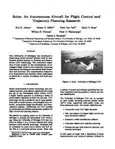
Fig. 1. Concepts of autonomously interacting control flow checker that can monitor the program counter and detect false jumps or branches based on information of the compiled code. Moreover, the checker should also be able to correct false jumps or branches.
Robustness, reliability and security are essential requirements of todays SoCs (Systems on Chips). Modules and their integration in the system have to be designed to be still operational also in difficult and inference-prone areas as well as insecure environments. In this paper, our goal is to investigate methods to recognize, analyze, and correct sporadic and/or permanent errors occurring in the control paths of embedded RISC-CPUs. Our vision thereby is to define autonomously behaving elements to resolve functional errors of a RISC-CPU-Core locally inside the core. These autonomous elements called control flow checkers are supposed to recognize, evaluate, and correct errors during the program execution of the processor. In particular, soft errors [2] as well as malign security attacks [3] are in the focus of this paper. In the following, we propose such concepts and an implementation of a corresponding control flow checker hardware (see Figure 1). The main task of the control logic in a CPU is to control the program flow. The actual state of execution of a program is, in general, given by the value of the program counter and the CPU registers. Usually, the next instruction to fetch is given by an increment of the program counter, but also branches and jumps may occur. Sources of errors that we want to autonomously detect and correct include accidental sporadic, permanent, or intended errors caused by local attacks that try to manipulate the program execution. These errors can effect a wrong program counter value. Errors may also be caused by pure software means such as buffer overflows. Here, a wrong jump destination or a wrong return address from a subroutine might cause an execution of infiltrated code. If an error is detected, the control flow checker should be able to initiate the reexecution of the control flow instruction. Definition 1. Control flow checking denotes the task to test whether a sequence of program counter values is correct with respect to a given program specification. The paper is structured as follows: In Section 2, a general overview of related work is given. In Section 3, we present a classification of control flow instructions. Subsequently, in Section 4, two different methodological concepts for control flow
3
checking are introduced. Architectural concepts for implementing these ideas present the focus of Section 5. Finally, in Section 6, we present an implementation of an autonomous control flow checker for a given real Leon3 [4] CPU and analyze the corresponding overheads for control flow checking in Section 7. Section 8 concludes the work.
2
Related Work
Error detection and correction methods have important roots in the area of fault-tolerance. Here, one of the most familiar method for error detection is the duplication of a given processor core with subsequent comparison of the results [5]. Duplication of processing units is, however, too cost-intensive and thus often prohibitive due to cost (area) and power consumption. Hence, these approaches are only used in safety-critical systems with a high demand on reliability. In the following, we first define relevant criteria when comparing different methodologies for control flow checking quantitatively. Here, the following criteria will be used: Error coverage denotes the degree of faults that can be detected by a method. For example, some methods for control flow checking discussed in the following can only detect a certain type of control flow instructions (e.g., direct branches and jumps). Some may detect not 100% of all control flow errors. Another criterion for comparison is the detection latency. The detection latency denotes the time between occurrence of a fault and its detection. This time is important to prevent a system failure. Only if an error is detected with a low latency, the error handling can react to transfer the system into a secure state or to trigger error correction measures. On the other hand, the following overheads may be caused: execution time overheads (CPU time), memory overheads and area overheads (hardware cost overheads). Related work on control flow checking can be divided into approaches using an additional hardware checker unit or a watchdog processor [6–10], and approaches which are completely software-based [11]. In these approaches, the program code is first structured into basic blocks1 . Control Flow Checking using Assertions (CCA) [11] denotes a software-based approach. After creating a basic block graph, a sequence of special control instructions is inserted into the program code at the beginning as well as at the end of each basic block. These additional instructions verify that only legal branch or jump destinations according to the specification, given by the basic block graph is taken. The advantage is that no additional hardware (area overhead) is required, but this approach has an obvious impact on the performance of the program code (execution time overhead). Undesired jumps caused by faults occurring on instructions inside a basic block cannot be detected at all. 1
A basic block is a sequence of code which is executed successively without any jumps or branches except at the end. The basic block can only be left at the end of a block and can only be entered at the beginning. Only the last instruction can be a jump or branch and only the first instruction can be a jump or branch destination (see Section 4.1).
4
A good overview over software methods for control flow checking for security and fault tolerance is given in [12]. To check all types of instructions, a signature (hash or a CRC value) of all instructions of a basic block can be calculated offline (at compile time). At runtime, a hardware checker can calculate the signature of the executed instruction in a basic block. When leaving a basic block, the signatures can be compared and errors inside the basic block can be found. Signature methods can be divided into two groups, namely Embedded Signature Monitoring (ESM) [6–8] and Autonomous Signature Monitoring (ASM) [9, 10]. In the ESM methods, the offline calculated signature (golden signature) is stored in the program code with additionally inserted instructions at the end of each basic block. These instructions read out the calculated signature of the executed instructions from the checker unit and compare it to the golden signature. The advantage of these methods is that all types of instructions can be checked and a new program contains already the corresponding signature. The disadvantages are a significant performance impact (execution time overhead) and that a fault can only be detected at the end of a basic block which may be too late to prevent a system failure (detection latency). Also, a single event upset during the execution of the additionally inserted instruction can lead to a false detection or spoofing of an error. In the ASM methods, the golden signature is stored in a separate memory belonging to the checker unit. Also, the comparator for the golden and the calculated signature is implemented in hardware. The information of the basic block graph is mapped into microinstructions, located inside the instruction memory of the checker. Jumps and branch destinations can thus also be checked. The advantages are that the program code must not be altered and that there is no performance impact. Also, all types of instructions can be monitored. The disadvantages are that an extra memory for the checker unit is required (memory overhead) and that synchronization between the CPU and the checker unit is difficult. So, interrupts, multi threading, and indirect jumps cannot be completely covered. An ASM approach for security applications is described in [10]. The IntraProcedural Control Flow Checking is similar to our method. The advantages of our methods however is, that we are a) more flexible in using memories to store the control flow (instruction) graph instead of a finite state machine in logic. Moreover, we have b) no performance impact in the error free case, and c) our checker unit is simpler and thus requires less resources. Finally, the Diva approach [13] describes a pipeline which accepts only checked results for the further processing after the commit phase. A redundant second pipeline is a simple rudimentary pipeline, where the results of arithmetic functions are recalculated with a separate checker, and memory items are refetched. The weakness is that the second pipeline is assumed to be fault-free, which might not be the reality in today’s deep submicron designs. The area overhead of Diva is lower than in the case of fully redundant units, but also performance reduction exists due to a longer pipeline.
5
3
Branches and Jumps
Control flow instructions (CFI) can be categorized into conditional branches and unconditional jumps. Conditional branches depend on the result of a logical or arithmetic operation. Both groups of control flow instructions can be subdivided into direct (static) and indirect (dynamic) jumps or branches. The destination of direct branches or jumps is fixed at compile time and is encoded into the jump or branch instruction in an absolute or relative address. For indirect jumps or branches, the destination address is determined during program execution. The destination address is given by either a register value or as the result of an operation with registers or the result of an operation with a register and a constant value which is encoded into the instruction. Absolute or relative addressing modes can be used there. Summarizing, four types of control flow instructions exist: (Unconditional) direct jumps (e.g., call, goto), (Conditional) direct branches (e.g., if .. then .. else), (Unconditional) indirect jumps (e.g., return from subroutine), and (Conditional) indirect branches. Furthermore, the class of unconditional indirect jumps can be subdivided into returns from subroutine, register indirect calls and other jumps. A return from subroutine is an example of an indirect jump, because the program counter jumps to the address where the routine is called from, and this address is only known at runtime. Register indirect calls are calls where the address of called subroutine is determined at runtime. Finally, also jumps which are not triggered by an instruction can occur such as interrupts and traps. The destinations of interrupts are typically given by the start address of the main interrupt service routine, and so, interrupts are direct jumps. Traps occur on exception conditions (like divide by zero). Here, the program jumps to the address of an exception handler, and so, traps can be treated as direct jumps. Table 1 presents an analysis of the occurrence rates of these different types of branches and jumps on the SPARC architecture for the SPEC CINT2000 benchmark [14] for a given list of programs. As been seen, indirect calls and jumps occur relatively rarely as opposed to direct branches and jumps.
4
Methods for Autonomous Control Flow Checking
In SoCs, a CPU often executes only a few specified programs over lifetime. This holds true particularly for embedded applications where the system is often only programmed once, and the code is never changed during the lifetime of the product, except for the update of the SoC with a new firmware and software. Furthermore, it is well known that in many computational intensive problems, most of the execution time is spent in only few subroutines. So, it is beneficial to analyze these subroutines for branches and jumps statically. If we assume that only direct jumps and branches exists in a given code segment, we are able to check the control flow of this code by verifying the
6 SPEC direct indirect program branches jumps returns calls other jumps gzip 1426 599 111 4 0 gcc 54676 22340 2188 140 273 vpr 2810 2065 248 2 7 mcf 288 82 26 0 0 crafty 4544 3848 77 0 11 parser 3189 1703 320 0 2 gap 18733 4158 828 1262 5 vortex 12537 8491 913 15 21 bzip2 748 380 73 0 0 twolf 5701 2060 189 0 2 Table 1. Accumulated number of control flow instructions of benchmarks of the SPEC CINT2000 test suite [14] when compiled to the SPARC [15] architecture.
correct execution of each direct control flow instruction as well as the (successively) linear execution of all the other instructions (the program counter value is incremented by one word address after each instruction). To check the correct execution of control flow instructions, we need to check the correct address of the control flow instruction and the correct target address. The program counter value before and after the execution of a control flow instruction can be compared to these addresses. If there is a mismatch, an error signal may be raised. In the following, we propose two alternative methods to obtain the correct addresses of control flow instructions of a given machine program and the corresponding targets. The first method is called basic block or control flow method (CF). The second method is called control flow instruction method (CFI). 4.1
Control Flow (CF) Method
First, a given compiled machine code is separated into a set of basic blocks BB. The following instructions define the begin of a basic block: a) the first instruction in a program or segment, b) the instruction following a control flow instruction, c) instructions which are destinations of control flow instructions. From this information, the control flow graph CF G(BB, T ) is built: Each node BBi ∈ BB of the control flow graph represents a basic block. The nodes are sorted with increasing start address of the corresponding basic block in ascending address order. Each edge t ∈ T represents a transition of the control flow from one basic block to another. If the last instruction of a basic block BBi is a direct branch instruction, the basic block has two successors. One is the basic block next in the list BBi+1 (if the branch is not taken), and to a basic block where the first instruction is the branch destination (if the branch is taken). Jumps have only one successor, and if the last instruction is not a control flow instruction, the successor basic block is always the next basic block BBi+1 . An example
7
Fig. 2. An example program code is given on the left side with the corresponding assembler code. The CFIs are denoted A to C, and the CFI destinations with a to c. D denotes the end of the program or segment to be checked. Furthermore, the code is divided into basic blocks, denoted with 1 to 6. In the middle, the corresponding CFG and on the right side, the corresponding CFIG are shown.
program is shown in Figure 2 which is separated into basic blocks. Also, the corresponding CFG is shown. With the given CFG, we have all information to check a sequence of program counter values for correctness as follows: The information of the CFG can be either used to directly define a finite state machine (FSM) to check the correctness of control flow instructions. Alternatively, an implementation using microinstructions of a microprogrammed circuit can be deducted from the CFG. For an implementation of a microprogrammed circuit, the information of the CFG can be stored inside memories. We need for each basic block, the start and the end address and also the successors basic blocks indexes. The start address of a basic block is the end address of the previous basic block incremented by one. To minimize the memory overhead, we need only the end address and a global start address. Also, we need to store only one successor of the basic block for branches because if the branch is not taken, always the basic block with the next index (BBi+1 ) is the successor. The correct control flow instruction address may directly be stored inside the memory (basic block end address). The corresponding target address is the start address of the successor basic block, given by its index. To get this address, the end address of the basic block with the previous index is fetched and the address is incremented (BBi−1 + 1). Having both addresses, the control flow instruction can be verified. For example, [10] describes a CF method, where the CFG is implemented in a FSM and the lookup table for resolving the control flow instruction addresses and indexes is implemented in memories.
8
4.2
Control Flow Instruction (CFI) Method
In case of direct branches and jumps, the start and target address is known at compile time. So, it is possible to extract this information from the binary or the disassembled program code by decoding the instructions. The control flow instructions are then sorted by increasing addresses in ascending address order. Then, the control flow instruction graph (CF IG(CF I, T )) is built: Here, each control flow instruction in the code which should be checked represents a node (CF Ii ∈ CF I). The edges of the CFIG denote transitions t ∈ T to the following control flow instruction. Like in a CFG, each node can have a maximum of two successors: two for a branch instruction and one in case of a jump instruction. For a branch instruction CF Ii , one successor is CF Ii+1 (branch is not taken). The other successor of a direct branch and jump instruction is CF In which is the next control flow instruction in the program code after the branch destination (branch is taken). The CFIG from the example program code is shown on the right side in Fig. 2. Like in the CF method, the information of the CFIG can be used as a specification of a control flow checker unit and implemented either directly by a FSM or as microinstructions of a microprogrammed circuit. For the microprogrammed circuit, we store for each CF I the start and the target address in memory. Also the index of the successor CF I must be stored inside this memory. For direct branches, we store the successor CF I for taken branches. If the branch is not taken, the successor CF I is CF Ii+1 . 4.3
Methods Conclusions
Both introduced methods can only check direct branches and jumps, where start and destination address can be extracted from the compiled code. For indirect control flow instructions, we will present extensions for both methods. Some of these extensions are discussed later. The advantage of the CF method is that in the most cases, fewer additional memory resources are needed than the CFI method. Furthermore, we can extend this method to check the integrity of all types of instruction sequence inside a basic block with a CRC or hash value. This value can be run time calculated from the executed instructions and can be compared at the end of a basic block with a precalculated value [9]. The disadvantage of the CF method is that we need two times access to the memory for each control flow instruction. One access for the end address of the basic block and one for the start address of the successor basic block. To ensure that on a branch or jump the correct start and destination address is available, we can preread both values. But this preread can only be done if the basic block has more than one instruction. If a basic block consists only of one instruction, we must stall the processor pipeline to verify the control flow instruction. The advantages of the CFI method are that the checker unit is very simple and uses only few logic resources. Also we have no performance impact, because the correct control flow instruction address and target address may be loaded from the memory in a single clock cycle. The disadvantages are that usually
9
more memory resources are needed as for CF method, and that we are not able to check the integrity of non-control flow instructions.
5
An Architecture for Lightweight Control Flow Checking
In the following, we introduce an architecture of a lightweight control flow checker to monitor and to correct the executed control flow instructions of a RISC CPU. Our approach can monitor direct jumps and branches as well as call and returns from subroutine. To achieve a correction of a corrupt program, a detected incorrect jump or branch can be reexecuted. Our checker is called lightweight, because with little area overhead, we can detect and correct many though not all errors. Our architecture concept is modular in the sense that coverage aspects can be treaded off with implementation overheads. 5.1
Handling of Direct Jumps/Branches
We are using the CFI method described in Section 4.2 to check direct jumps and branches where the CFIG is implemented in a dedicated memory. The checker must know the instruction’s program address and the address of the next instruction to execute. Since most CPU architectures today are pipelined, these addresses can easily be taken from successive pipeline stages of the program counter. If no jump or branch instruction occurs, the next instruction address P Cn+1 is typically one instruction word higher than the value of the current program counter P Cn . So, an incremented instruction address can be compared to the address after the instruction (see comparator a in Figure 3). If the current instruction is a direct jump or branch instruction, the next program counter is the jump destination, or, in the case of a branch the branch destination, or, if the branch is not taken, the next address in the program code. Each pair of control flow instruction address and target address is stored in two RAMs of the checker unit, one for the start and one for the target address (see Figure 3). The addresses of the branch or jump instructions are stored successively in the start address RAM (sAdrRam) and the corresponding targets in the jump address RAM (jAdrRam). Also, a checker unit program counter (CUPC ) is needed which points in these RAMs to the cell, where the address of the next direct branch or jump is stored. This start address is compared to the current program counter to determine when the branch or jump instruction is executed (comparator b). In this case, the following program counter value is compared to the address of the jump address RAM to verify the correct execution of the branch or the jump (comparator c). Now, the CUPC must point to the next branch or jump address. This can be achieved by introducing a third RAM (ctrlRam) where the next CUPC is stored for each branch or jump. In the case of a branch, it must also be determined if the branch is taken or not. If the branch is taken, the next CUPC has the value which is stored in the ctrlRam. If the branch is not taken, then the CUPC can be incremented. The CUPC and the
10
Fig. 3. Architecture for control path checker with the three Rams and comparators. Also, the control unit program counter (CUPC ) is shown.
ctrlRam presents a microprogrammed architecture which implements the CFIG. The CUPC can be compared with the index of the CF I. The transitions of the CFIG are stored in the ctrlRam. Also, control flags are stored in the ctrlRam. So, the checker unit can distinguish between jumps or branches or can activate or deactivate the checker unit based on specific program addresses. This can be done by storing the checking start or end address in the sAdrRam and setting the checking start or end flag in the corresponding cell in the ctrlRam. If the program flow reaches the starting address, the checker unit will be activated, or, if the checking end address is reached, the checker unit deactivates itself. Finally, parts of the program flow, e.g., non-critical sections or sections which can not be checked due to not supported indirect jumps, might be excluded from the checking process by setting the checking start and end flags.
5.2
Handling of Calls and Returns
The most frequent use of indirect jumps occur in the form of returns from subroutine. By executing a return from subroutine instruction, the program counter jumps to the next address after the instruction from where the subroutine was called from. The return address is typically stored in a CPU register, so the return instruction is a special indirect jump. Returns can be verified also in our approach by introducing an additional hardware stack. Upon a call (direct or indirect), the return address is stored in the stack and when the return instruction is executed, the target address can be verified.
11
5.3
Correction by Reexecution
If a faulty jump or branch instruction occurs, this instruction will be reexecuted as follows: The error can be detected fast enough to ensure that the state of the CPU is not altered by the faulty instruction execution. To guarantee this, the checker must monitor the program counter in the first pipeline stage of a CPU. Unfortunately, in most architectures, the jump or branch instructions need more than one cycle to execute. So, until the error is detected, some other instructions after the jump might be executed. After error detection, the program counter is reset to a value previous the error occurs by looping back the program counter value from a subsequent pipeline step. The details of the reexecution process depends highly on the processor architecture and design. The SPARC architecture allows to execute one instruction after a branch instruction or two instructions after a jump instruction before the branch or jump is performed (see [15]). If an error is detected and the jump or branch instruction must be reexecuted, also these following instructions must be reexecuted. It must also be ensured that these instruction cannot alter the state (e.g., register content or memory operations) of the CPU before reexecution (see Section 6).
6
Implementation
We implemented and analyzed our methods of lightweight control flow checking for the open source SPARC CPU Leon3 from Gaisler Research [4] in a Virtex 4 FPGA from Xilinx. The checker can monitor direct branches, jumps and calls as well as indirect returns and has also the possibility to reexecute a corrupted jump or branch instruction by fetching it again from the memory. Other features of the checker are the support of the activate and deactivate procedures described in Section 5.1. The complete methodology for control flow checking consists of the concept of checking of direct jumps and branches (Section 5.1), the return stack (Section 5.2) and the repair mechanism (Section 5.3). To minimize the resource overhead, some features can be disabled (see Section 7). Indirect jumps which are not returns, are not supported so far, but many application programs or routines in embedded systems have none of these instructions. The checker is placed between the first pipeline stages of the Leon3 core (see Figure 4). The current program counter for the checker is the program counter in the decode pipeline step and the next program counter is the program counter of the fetch pipeline step. For reexecuting a jump or branch, the program counter of the memory step is looped back to the program counter generation (a step prior to the fetch step), and the instructions are annulled after the memory step, so the incorrect instructions are not executed and no registers or memories are written. Because of the loop back, the jump is executed again, and if this execution is correct, the program is continued normally. To prepare an application, the compiled code is analyzed by a program which decodes the instructions and searches for jumps, branches, calls and returns (see Figure 5). The addresses of these instructions are stored in the sAdrRam initialization file and the destination address, except for the return instruction,
12
Fig. 4. The checker unit is placed between the first pipeline stages of the Leon core [4]. All bold lines denote new paths for monitoring and reexecution of jump and branch instructions.
Fig. 5. From the compiled code, the program analyzer extracts all branches, calls, and returns and generates the memory initialization files for the sAdrRam, jAdrRam, and ctrlRam. The checker rams can be initialized during the synthesis or later in the bitfile with the data2mem tool.
is stored in jAdrRam initialization file. Also, the initialization file for the control Ram (ctrlRam) is generated, and the activate and deactivate instructions for the checker unit are inserted. The original program of the application remains completely unchanged. The memory initialization files can be used for the synthesis of the checker unit, or the content of the rams can be initialized directly in the bitfile of the FPGA with the Xilinx tool ”data2mem”. For future FPGA and ASIC versions of the checker, the memories could be initialized also at runtime over a memory bus or the processor.
7
Overhead Analysis
Next, we analyze the number of entries of the checker rams (sAdrRam, jAdrRam, and ctrlRam) and the area overhead of the checker for different supported features. Furthermore, the verification process of the checker unit is described in this section.
13 SPEC program gzip gcc vpr mcf crafty parser gap vortex bzip2 twolf checker ram entries 2138 79206 5125 398 8471 5214 23721 21943 1203 7952 Table 2. Number of required entries in the checker rams for different programs of the SPEC CINT2000 benchmark [14].
Overhead LUTs Flip Flops BRAMs LUTs Flip Flops BRAMs LUTs Flip Flops BRAMs LUTs Flip Flops BRAMs
Leon3 Version A Version B checker rams with 512 entries % 17031 106 0.62% 242 1.42% % 5412 11 0.20% 17 0.31% % 50 3 6% 3 6% checker rams with 1024 entries % 17031 111 0.65% 248 1.46% % 5412 12 0.22% 18 0.33% % 50 5 10% 5 10% checker rams with 2048 entries % 17031 112 0.66% 250 1.47% % 5412 13 0.24% 19 0.35% % 50 8 16% 8 16% checker rams with 4096 entries % 17031 105 0.62% 251 1.47% % 5412 14 0.26% 20 0.37% % 50 10 20% 10 20%
Version C 259 1.52% 20 0.37% 3 6% 265 1.56% 21 0.39% 5 10% 267 1.57% 22 0.41% 8 16% 268 1.57% 23 0.42% 10 20%
Table 3. Area overheads of different checker unit versions for a Leon3 core without PCI and Ethernet. The area and memory overhead of the full version C and the reduced versions (A and B) and for different checker ram sizes are shown.
We analyze the number of required entries of the checker ram for the SPEC CINT2000 benchmark [14] compiled to the Leon processor. Table 2 shows the number of checker ram entries of different programs of the benchmark. Operating system routines and standard library functions are not included in this analysis. Next, we provide different versions of the checker which support different jump instructions and error detection features resulting in different area overheads. The smallest version of the checker (version A) can only monitor direct jumps or branches. All indirect jumps are not supported and not allowed in the code, but it is allowed that indirect jumps can occur in the unchecked code. This includes also returns from subroutine, so this technique can only be used for a single procedure or function. But many of these procedures and functions can be checked if the checker unit is deactivated at calls and returns, and activated inside the function. The second version (version B) is version A with an additional 32 entry return stack. With this version, we can also monitor calls and returns, so the most application programs can be fully monitored.
14
The last version (version C) has the additional capability of repeating an incorrect jump or branch instruction as described in Section 5.3 and Section 6. Table 3 shows the overhead of different versions, synthesized and implemented on a Virtex 4 with ISE 8.2 with different checker ram sizes. The results show that the area overhead for logic (lookup tables and Flip Flops) is very small. If more control flow instructions shall be monitored and more checker ram entries are needed, only the overhead of the block rams increases. A qualitatively comparison of the overhead to other approaches is difficult due to different target architectures. The verification of the checker has been performed by simulation and the Leon in-circuit debugger. Instruction faults are simulated between the instruction cache and the integer unit by an XOR with an error mask, read in from a file. With the in-circuit debugger, control flow instructions can be altered inside the memory (for example the jump destination encoded inside the instruction). With these techniques, the checker and the correction of incorrect jump instruction has been verified.
8
Conclusions and Future Work
We introduced a systematic methodology for autonomous control flow checking for embedded RISC CPUs which can monitor direct jump and branches as well as returns from subroutine. Experimental results show that the additional hardware overhead is small. In particular, lookup tables and Flip Flops overhead amount to an overhead of less than 2% in all cases. So, the only overhead results from the additional memory needed to monitor the control flow instructions. A modular concept for generation of checker units has been proposed, so the area overhead can be further reduced, by removing some functions. The detection of faults is very fast, so we have the possibility to react immediately during the execution of a faulty instruction and are able to prevent incorrect instructions from being executed. Furthermore, an incorrect jump or branch instruction can be refetched and reexecuted. With this technique, we therefore have no performance impact on the CPU and the compiled program code remains unchanged. We introduced a second independent program counter CUPC with its own state machine and own microcode with own microinstructions (ctrlRam). The checker program code is based on the extracted branch and jump instructions from the program code at compile time. This reduced code covers only direct branches or jumps without the instructions between two branch points. With this technique, we enhanced the CPU with a reduced second independent program counter and instruction unit at minimum additional hardware cost and full control of the program flow. Further extensions can be the support of indirect jumps, multi threading, and the check of the conditionals of branches. Also, an interface to the operation system could be usefully to count the errors and to report the reliability of the CPU. Finally, if the checker unit has a bus interface, the contents or part of the content of the checker rams may be stored in the system memory. Only the
15
content for checking the current part of program (e.g. the current function or a set of functions which are current in use) may be hold in the local checker rams. If the checker needs informations which are not stored inside the local checker rams, the checker can generate a page-fault-like event to signal the operating system to reload the checker rams with the needed contents. This concept of caching can reduce the the among of memory overhead significantly.
References 1. P. Ziegler, B.B.: Fliegendes Rechnernetz. In: CT, Heise Verlag (2005) 2. Lee, K., Shrivastava, A., Issenin, I., Dutt, N., Venkatasubramanian, N.: Mitigating soft error failures for multimedia applications by selective data protection. In: CASES ’06: Proceedings of the 2006 International Conference on Compilers, Architecture and Synthesis for Embedded Systems, New York, NY, USA, ACM (2006) 411–420 3. US-CERT: Vulnerability notes database CERT Coordination Center. http://www.kb.cert.org/vuls/ 4. Gaisler Research: LEON3 SPARC V8 Processor core. http://www.gaisler.com 5. M. Mueller, e.a.: RAS strategy for IBM S/390 G5 and G6. IBM J. RES. DEVELOP. 43(5/6) (1999) 6. Lu, D.J.: Watchdog processors and structural integrity checking. IEEE Trans. Computers 31(7) (1982) 681–685 7. Schuette, M.A., Shen, J.P.: Processor control flow monitoring using signatured instruction streams. IEEE Trans. Comput. 36(3) (1987) 264–277 8. Majzik, I., Pataricza, A., Cin, M.D., Hohl, W., Honig, J., Sieh, V.: Hierarchical checking of multiprocessors using watchdog processors. In: European Dependable Computing Conference. (1994) 386–403 9. Michel, T., Leveugle, R., Saucier, G.: A new approach to control flow checking without program modification. In: FTCS. (1991) 334–343 10. Arora, D., Ravi, S., Raghunathan, A., Jha, N.K.: Hardware-assisted run-time monitoring for secure program execution on embedded processors. In: IEEE Transactions on VLSI Systems, Washington, DC, USA, IEEE Computer Society (2006) 11. Goloubeva, O., Rebaudengo, M., Reorda, M.S., Violante, M.: Soft-error detection using control flow assertions. In: DFT ’03: Proceedings of the 18th IEEE International Symposium on Defect and Fault Tolerance in VLSI Systems, Washington, DC, USA, IEEE Computer Society (2003) 581 ´ 12. Abadi, M., Budiu, M., Ulfar Erlingsson, Ligatti, J.: Control-flow integrity. In: CCS ’05: Proceedings of the 12th ACM Conference on Computer and Communications Security, New York, NY, USA, ACM Press (2005) 340–353 13. Austin, T.M.: DIVA: A reliable substrate for deep submicron microarchitecture design. In: International Symposium on Microarchitecture. (1999) 196–207 14. Standard Performance Evaluation Corporation (SPEC): SPEC CPU2000 V1.3. http://www.spec.org 15. SPARC: The SPARC Architecture Manual V8. http://www.sparc.com/standards/V8.pdf