Software Signatures (CFCSS); CFCSS is a pure software method that checks .... Signature monitoring and pure software methods have been proposed to ...... Detection Mechanism,â Dependable Computing for Critical Applications 2, Springer-.
Center for Reliable Computing
TECHNICAL REPORT
Control Flow Checking by Software Signatures Nahmsuk Oh*, Philip P. Shirvani and Edward J. McCluskey
CRC-TR 00 - 4 April, 2000
Center for Reliable Computing Gates Building 2A, Room 236 Computer Systems Laboratory Dept. of Electrical Engineering and Computer Science Stanford University Stanford, California 94305-9020
ABSTRACT This paper presents a new signature monitoring technique called Control Flow Checking by Software Signatures (CFCSS); CFCSS is a pure software method that checks the control flow of a program using assigned signatures. While special hardware for error checking is required in other signature monitoring techniques, CFCSS does not need the help of extra hardware for error detection; this is the advantage of CFCSS. We have developed an algorithm that assigns a unique signature to each node in the program graph and adds instructions for error detection. Signatures are embedded into the program during compilation time using the constant field of the instructions and compared with run-time signatures when the program is executed. Furthermore, we have developed an algorithm to reduce the code size and execution time overhead caused by checking instructions in CFCSS. We performed a branching fault injection experiment with benchmark programs. In the benchmark programs without CFCSS, an average of 33.7% of the injected branching faults produced undetected incorrect outputs; however, in the programs with CFCSS, only 3.1% of branching faults produced undetected incorrect outputs. CFCSS increased the error detection capability by an order of magnitude without the help of extra hardware added for error detection. The distinctive feature of the CFCSS over previous signature monitoring techniques is that CFCSS needs no dedicated hardware such as a watchdog processor for control flow checking because it is a pure software method. A watchdog task in multi-tasking environment also needs no extra hardware, but the advantage of the CFCSS over it is that CFCSS can be used even when the operating system does not support multi-tasking. FUNDING This work was supported in part by the Ballistic Missile Defense Organization, Innovative Science and Technology (BMDO/IST) Directorate and administered through the Department of the Navy, Office of Naval Research under Grant Nos. N00014-92-J-1782 and N00014-951-1047 Imprimatur: Nirmal Saxena and Subhashishi Mitra
i
TABLE OF CONTENTS
1.
INTRODUCTION .....................................................................................................1
2.
SIGNATURE ANALYSIS BY INSTRUCTIONS ......................................................2
3.
PRELIMINARIES.....................................................................................................3
4.
DESCRIPTION OF CFCSS ......................................................................................4 4.1
THE RUN-TIME SIGNATURE G......................................................................................4
4.2
THE RUN-TIME ADJUSTING SIGNATURE D......................................................................9
4.3
ALGORITHM A........................................................................................................11
4.4
ALIASING ...............................................................................................................13
5.
EXPERIMENTAL RESULT....................................................................................15
6.
OVERHEAD REDUCTION AND EXAMPLES.....................................................18
7.
SUMMARY.............................................................................................................20
8.
REFERENCES ........................................................................................................20
ii
LIST OF FIGURES Fig. 3.1. A program and its graph..........................................................................................3 Fig. 4.1. The detection of an illegal branch............................................................................5 Fig. 4.2. A basic block with checking instructions................................................................55 Fig. 4.3. The checking instructions in a correct control flow..................................................7 Fig. 4.4. The detection of an illegal branch............................................................................8 Fig. 4.5. The detection of a branch illegally jumping to the middle of a basic block..............9 Fig. 4.6. The detection of a branch illegally jumping to the second instruction of a basic block.............................................................................................................................9 Fig. 4.7. Nodes v1 and v3 have the same signatures ...............................................................10 Fig. 4.8. Nodes v1 and v3 have different signatures ...............................................................11 Fig. 4.9. Aliasing causing an undetectable control flow error...............................................14 Fig. 5.1. Percentage of faults not detected............................................................................17 Fig. 6.1. Two examples of Algorithm B................................................................................19 Fig. 6.2. Checking instructions in Algorithm B.....................................................................19
iii
1. INTRODUCTION Transient or permanent faults introduced in a computer system during runtime can cause an incorrect sequence of instruction execution in the program and may cause control flow errors. If the system does not perform some run-time checking, the erroneous output may not be detected and serious damage may result. Therefore, it is important to monitor the program to detect any abnormality in the control flow or other error, and to take appropriate actions to avoid any incorrect output. Signature monitoring and pure software methods have been proposed to check the control flow of a computer system. Signature monitoring is a signature analysis method in which a signature associated with a block of instructions (one or more nodes in the control flow graph) is calculated and saved somewhere during compile time; then, the same signature is generated during run time and compared with the saved one. Signatures are assigned arbitrarily (assigned signature) or derived from the binary code or the address of the instructions (derived signature). Structural Integrity Checking (SIC) [Lu 82] employs an assigned signature method while Path Signature Analysis (PSA) [Namjoo 82], Signatured Instruction Streams (SIS) [Shen 83], Asynchronous SIS (ASIS) [Eifert 84], Continuous Signature Monitoring (CSM) [Wilken 89],[Wilken 90], extended-precision checksum method [Saxena 90], and On-line Signature Learning and Checking (OSLC) [Madeira 92] all use derived signatures. In many signature monitoring techniques, dedicated hardware is used to calculate the run-time signatures and to compare them with the saved signatures. A watchdog processor is proposed for this purpose in [Lu 80] and [Mahmood 85].
On the other hand, when the
hardware is fixed and cannot be changed, a software method that does not need any extra hardware has to be developed. Examples of software methods are assertions [Andrews 79], [Ersoz 85], watchdog task [Ersoz 85], Block Signature Self-Checking (BSSC) [Miremadi 92], Error Capturing Instructions (ECI) [Miremadi 92], timers to check the behavior of the program [Madiera 93], Available Resource-driven Control-flow monitoring (ARC) [Schuette 94], and temporal redundancy methods [Ignatushchenko 94]. An assigned signature monitoring technique called Versatile Assign Signature Checking (VASC) has been proposed and evaluated in [Furtado 96], in which the comparison of the ratio between control flow errors and data errors in RISC and CISC processors are reported.
1
2. SIGNATURE ANALYSIS BY INSTRUCTIONS This paper presents a new assigned signature monitoring technique called Control Flow Checking by Software Signatures (CFCSS), which monitors assigned signatures for interblock control flow checking using instructions without using any special hardware.
The
program is divided into basic blocks. A basic block is a branch-free sequence of instructions; no jumps into or out of the block except for the first and last instruction of the block.
A
node in the program graph (explained in detail in Sec. 3) represents each basic block.
All
nodes in the program graph are assigned different arbitrary numbers (signatures), which are embedded into the program during preprocessing or compile time.
During program
execution, a run-time signature G is stored in one of the general purpose registers called the global signature register (GSR), and compared with the stored signature of the node whenever control is transferred to a new node. A run-time adjusting signature D is combined with G for multiple branching cases. The complete algorithm and an example program are presented in Sec. 4. CFCSS differs from other signature monitoring techniques in using no watchdog processor or extra hardware to achieve inter-block control flow checking.
CFCSS uses an
assigned signature technique similar to Structural Integrity Checking (SIC) [Lu 82], but does not need to send check-labels to a watchdog processor since it checks the signatures using instructions.
Block Signature Self-Checking (BSSC) [Miremadi 92] is also an assigned
signature technique that uses a subroutine to replace the watchdog processor. However, its drawback is that the code depends on the location of the code because the signature consists of an absolute address. The control flow checking scheme presented in [Yau 80] is a pure software method but it constructs a database containing information about concurrent control flow checking, thus it may require significant memory overhead. The watchdog task described in [Ersoz 85] also needs no extra hardware, but the operating system must support a multi-tasking environment. On the other hand, a watchdog processor or similar monitoring hardware is required in the derived signature techniques as in Path Signature Analysis (PSA) [Namjoo 82], Signatured Instruction Streams (SIS) [Shen 83], Asynchronous SIS (ASIS) [Eifert 84], Continuous Signature Monitoring (CSM) [Wilken 89] [Wilken 90], extendedprecision checksum method [Saxena 90], On-line Signature Learning and Checking (OSLC) [Madeira 92] and Implicit Signature Checking (ISC) [Ohlsson 95].
They check the intra-
block and inter-block control flow by observing the signatures derived from the instruction bit patterns or addresses of a basic block while CFCSS checks the inter-block control flow by monitoring assigned signatures in the GSR. The GSR differs from the reserved register in [Tung 90]; the reserved register stores the program or procedure name whereas the GSR stores the signature of the current node. The GSR is not a special or additional register in the CPU. It is one of the general purpose registers of the CPU picked by the compiler or
2
assembler to serve as the GSR. In addition, CFCSS differs from VASC [Furtado 96] in the way it embeds and checks for the signatures.
3. PRELIMINARIES Before we present our approach, we define the terminology that will be used later. A basic block is a maximal set of ordered instructions in which its execution starts from the first instruction and terminates at the last instruction.
There is no branching
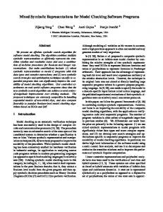
instruction in a basic block except possibly for the last one. A basic block terminates at either an instruction branching to another basic block or an instruction receiving transfer of control flow from two or more places in the program [Yau 80] [Namjoo 83]. By defining V = {v1, v2, ..., vn} as the set of vertices denoting basic blocks, and E = {br ij| br ij is a branch from vi to vj} as the set of edges denoting possible flows of control between the basic blocks, a program can be represented by a program graph, P = {V, E}. These brij’s are not necessarily explicit branch instructions. They also represent fall through execution paths, jumps, subroutine calls and returns. An example is shown in Fig. 3.1.
L1:
I1 I2 I3
V1
L2:
I4 I5
V2
I6 I7 I8
I1,I2,I3
I4, I5
V3
I6,I7,I8
V4 I9,I10
L3:
I9 I10
L4:
I11 I12
V5
I11,I12
E = { br12, br23, br24 , br34, br42, br45, br15 } V = { v1, v2, v3, v4, v5 } Fig. 3.1. A sequence of instructions and its graph Vertex vj is in the set suc(vi) if and only if brij is included in E. Similarly, vertex vi is in the set pred(vj) if and only if brij is included in E. If a program is represented by its program graph P = {V, E}, brij (a branch from vi to vj during the execution of P) is illegal if br ij is not included in E [Yau 80]. This illegal branch indicates a control flow error, which 3
can be caused by transient or permanent faults in the hardware such as the program counter, address circuits, or memory system [Lu 82]. If a node receives more than two transfers of control flow, it is said to be a branchfan-in node. It means that the number of nodes in pred(v) is greater than one. A branch insertion occurs when one of the instructions in the node is changed to a branch instruction as the result of an error. A branch deletion occurs when an error causes the branch instruction of a node to change to a non-branch instruction. As a result, the node without the branch instruction merges with the node that is adjacent to it in the memory address space. The xor-difference of a and b is the result of performing the bitwise XOR operation of a and b, i.e., xor-difference = a ⊕ b, where a and b are binary numbers.
4. DESCRIPTION OF CFCSS 4.1 The run-time signature G The CFCSS checks the control flow of the program by using a dedicated register called the global signature register (GSR), which contains the run-time signature G associated with the current node (the node that contains the instruction currently executed) in the program flow graph. Every basic block (represented by a node v i in the program flow graph) is identified and assigned a unique signature si when the program is compiled.
Let G i be the run-time
value of G when the program flow is in node vi. Under normal execution of the program (no errors), G i should be equal to si.
If G contains a number different from the signature
associated with the current node, it means an error has occurred in the program. When control is transferred from one basic block to another, a new run-time signature G is generated by a signature function f at the destination node of the branch. A signature function f is a function that updates G for the current node by using two values: the signature of the previous node (source node of the branch) and the signature of the current node (destination node of the branch). We use these two values since the source and destination nodes of the branch uniquely determine each branch in E. Suppose that the signature function f is defined as f(G,di) = G ⊕ di, and ss and sd are the signatures of the source node vs and the destination node vd of branch brsd. The signature difference d d (d d = ss ⊕ sd) is calculated in advance at compile-time and stored in the destination node vd. Before the branch brsd is taken, G contains Gs (the signature ss of the source node vs). After the branch is taken, G is updated with a new value, Gd = f(Gs, dd), based on the previous value G s and the signature difference d d. If Gd is equal to the signature sd of the destination node vd, it means there is no control flow error. On the other hand, if Gd is different from sd, it tells us that a control flow error has occurred.
4
We chose the XOR operation as the signature function because the XOR operation is better than other ALU operations for the purpose of checking or generating signatures. As AND, OR and XOR operations use fewer gates in the ALU than addition and multiplication, they have less chance of having an error in the ALU than addition and multiplication. We want to check the correct control flow in the original program and minimize the probability of error in the signature function. The fewer gates the signature function uses, the smaller area in ALU an error can occur, so that the probability of error in the signature function decreases. Furthermore, AND and OR operations cannot uniquely determine one input given the other input and output. Therefore, the best candidate for the signature function is the XOR operation.
G1 = s 1
V1
s1 d1
G1 = s1
V1
V3
s1 d1
s3 d3
Illegal branch
G2 = s 2
V2
Correct branching
s2 d 2 = s1 ⊕ s2
V2
V4 G4 s4
s4 d 4 = s 3 ⊕ s4
Incorrect branching Gn : Run-time signature at the node vn sn : Signature assigned to the node vn d n : Signature difference
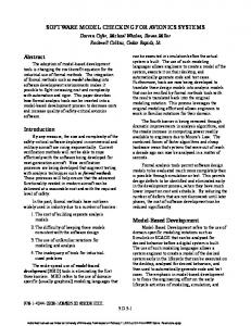
Fig. 4.1. The detection of an illegal branch For example, in Fig. 4.1, the signature function f is defined as f (G, di) = G ⊕ di and s1 and s2 are the signatures of the source node v1 and destination node v2 of the branch br12, respectively. Note that nodes are assigned unique numbers as their signatures. Before a branch is taken, G is equal to G1 that is the same as s1, the signature of the source node of the branch. After the branch is taken, G is updated with a new run-time signature G2, G = G2 = f(G1, d2) = G1 ⊕ d2. Since the signature difference d2 is d2 = s1 ⊕ s2 and G1 was s1, the new runtime signature G2 is G2 = f(G1, d 2) = G1 ⊕ d 2 = s1 ⊕ (s1 ⊕ s2) = s2, i.e., the updated run-time signature G2 is the same as the signature s2 of the current node v2, therefore, no error has occurred. On the other hand, suppose that an illegal branch from node v1 to node v4 is taken. In other words, the control should have moved from node v1 to node v2, but an error causes an
5
illegal branch from v1 to v4. Before the illegal branch is taken, G1 is equal to s1 as before. However, after the branch is taken, at node v4, the new updated run-time signature G4 is different from the signature s4 of the new node v4 because G 4 = f(G 1, d 4) = G1 ⊕ d 4 = G1 ⊕ (s3 ⊕ s4 ) =
s1 ⊕ (s3 ⊕ s4) ≠ s4, i.e., the control flow error can be detected by observing that the
run-time signature is different from the signature of the new node. Before going into the exact algorithm, the following describes the outline of the algorithm. A brief description of Algorithm A: All basic blocks (nodes) in the program are identified and numbered. Each basic block is assigned a unique signature. The signature difference (XOR-difference between the source and destination node) of all branches is also calculated and stored in the destination nodes of all branches. Whenever the control enters a new node, the run-time signature is updated to a new value G new by the signature function f that uses the previous run-time signature Gprev and the signature difference dnew as the arguments. If the new run-time signature G new is the same as the signature of the new node, the instructions in the node are executed. If G new is different from the signature of the new node, it means a control flow error has occurred and control is transferred to the error handling routine.
. . I1 I2 . . . In . .
G = G ⊕ dk
Bk
Bk
Instructions
br G≠sk error
I1 I2 . . . In
Basic block
Checking Instructions
I1 I2 . . . In
Basic block with checking Instructions
Vk
Node in the program flow graph
Fig. 4.2. A basic block with checking instructions To check the control flow, checking instructions are located at the top of each basic block, in other words, checking instructions are executed prior to the execution of the original instructions in the basic block. In Fig. 4.2, the basic block Bk consists of instructions I1, I2, ..., I n and additional checking instructions located at its beginning. The checking instructions consist of two parts: the signature function that generates the run-time signature (G = G ⊕ dk), and the branch instruction, ‘br (G≠s k) error’, that compares the run-
6
time signature with the signature of basic block Bk. In this way, a node vk represents a basic block Bk with the checking instructions associated with Bk.
G = G ⊕ d1 br G≠s1 error
V1
s 1 = 1011
V2
d2 = 1001 s 2 = 0010
B1
G1 = s1 = 1011
G = G ⊕ d2
G2 = G1 ⊕ d2 = 1011 ⊕ 1001 = 0010 = s 2
br G≠sk error
B2
G = G2 = s2 = 0010
Fig. 4.3. The checking instructions in a correct control flow
Fig. 4.3 shows how the checking instructions work to detect errors. The control is going to be transferred from node v1 to node v2. G is equal to G1 = s1 = 1011, the signature of the current node v1. After the branch br12 is taken, the signature function f generates the new run-time signature G = G2 = G1 ⊕ d2 = 1011 ⊕ 1001 = 0010, and G is compared with the signature s2 by the ‘br (G ≠ s) error’ instruction. The conditional branch instruction ‘br (G≠s) error’ branches to the error handler if G and s2 are different. In contrast, Fig. 4.4 shows the case where an illegal branch is taken and how it is detected by the checking instructions. Before an illegal branch br 14 is taken, G has the value s1. However, at node v4, the new run-time signature G = G4 is different from s4 since G is 0101 and s4 is 0110 (G4 = G 1 ⊕ d4 = 1011 ⊕ 1110 = 0101 ≠ s4 = 0110). This mismatch causes the following instruction ‘br (G≠s) error’ to transfer the control to the error handling routine.
7
G1 = s 1
V1
V3 s1 = 1011 d1 Illegal branch
V2
V4 G4 ≠s4
G = G ⊕ d1 s3 = 1000 d3
s4 = 0110 d 4 = s3 ⊕ s4 = 1110
br G≠s1 error
G = G ⊕ d3 G1 = s1 = 1011
br G≠s3 error
B1
B3
G = G ⊕ d2
G = G ⊕ d4
br G≠s2 error
br G≠s4 error
B2
B4
G4 = G 1 ⊕ d4 = 1011 ⊕ 1110 = 0101 ≠ s4
Fig. 4.4. The detection of an illegal branch Fig. 4.4 is the case where the illegal branch is taken to the location where the signature function instruction is located, i.e., the first instruction of the node.
Fig. 4.5
illustrates the case in which an error occurring in the branch instruction, for example, a bit flip in the destination field, causes an unpredictable jump to any place in the entire program, i.e., any basic block in the program and any place in that basic block. G has the value s1 at node v1. The illegal branch from node v1 to node v4 is taken and the control is transferred to one of the instructions in the basic block B4, not the checking instructions. As a new run-time signature is not generated at v4, G is still equal to the previous value G1. G is not updated to s4 although control is transferred to node v4. After the instructions in node v4 are executed, the branch from node v4 to node v5 is taken. At node v5, G is updated to a new value G5, but it is not equal to the signature of node v5 because the previous G before the branch br45 was G 1(= s1), not the correct value G 4(= s4). Thus an illegal branch to any instruction in the node will also be caught. The detailed calculation of G is shown in the figure. Fig. 4.6 shows the case where an illegal branch br14 lands at the second instruction of the node, i.e., ‘br (G≠s) error’. In a similar way, as the new run-time signature is not generated at v4, G is still equal to the previous value G1 that is not equal to s4. Therefore, ‘br (G≠s) error’ catches this mismatch and the error is detected.
8
B3 G = G ⊕ d1 G1 = s1
V1
s1 = 1011 d1
V3
br G≠s1 error s3 = 1000 d3
G1 = s1 = 1011
B1
G = G ⊕ d4 br G≠s4 error
Illegal branch
V4 V2
G4 ≠ s 4 V5
s4 = 0110 d 4 = s3 ⊕ s4 = 1110 s5 = 0011 d 5 = s4 ⊕ s5 = 0101
Illegal branch
B4
G4 = G1 ≠ s 4
G = G ⊕ d2 br G≠s2 error
B2
G = G ⊕ d5 br G≠s5 error
B5
G5 = G1 ⊕ d 5 = 1011 ⊕ 0101 = 1110 ≠ s5 G5 ≠ s5
Fig. 4.5. The detection of a branch illegally jumping to the middle of a basic block
G = G ⊕ d1 br G≠s1 error G1 = s1
V1
s1 = 1011 d1
G1 = s1 = 1011
B1
G = G ⊕ d4
Illegal branch
V4 V2
G 4 ≠ s4
br G≠s4 error G = G 1 = s1 ≠ s4 s4 = 0110 d 4 = s 3 ⊕ s4 = 1110
B4 G = G ⊕ d2 br G≠s2 error
V5
B2
G = G ⊕ d5 br G≠s5 error
B5
Fig. 4.6. The detection of a branch illegally jumping to the second instruction of a basic block
4.2 The run-time adjusting signature D It was shown that illegal branches violating the control flow can be detected by assigning unique signatures to each of the nodes in the program graph and adding signature checking
9
instructions to them. However, there are cases where the same signature has to be assigned to multiple nodes, for example, a branch-fan-in node. In Fig. 4.7, the two nodes, v1 and v3 have branches to the same node, a branch-fan-in node v5. If d 5 is the signature difference between nodes v1 and v5 as stated before (d5 = s1 ⊕ s5), there is no problem when the branch br15 is taken because G5 = G1 ⊕ d5 = s1 ⊕ s1 ⊕ s5 = s5, which is the signature of node v5. If the branch br35 is taken, however, the run-time signature G at node v5 is not equal to s5 as G5 = G3 ⊕ d 5 = s3 ⊕ s1 ⊕ s5 ≠ s5, if s3 ≠ s1. However, if we use s1 = s3 as the signatures, then an illegal branch from v1 to v4, or from v3 to v2, will not be detected. In order to solve the problem of assigning a same signature to multiple predecessors of a branch-fan-in node, a run-time adjusting signature D is introduced.
After the run-time signature G is generated by the signature generation
function, G is XORed with D to get the signature of the branch-fan-in node, thus, at the source node, D has to be set to the value which makes G equal to the signature of the destination node. Fig. 4.8 illustrates an example where D is used in the branch-fan-in node. At node v5, one more checking instruction G5 = G3 ⊕ D added.
After the signature
generation function G = G ⊕ d5, G is XORed with D which should be determined at the source nodes v1 and v3. Since d5 is initially set to the XOR-difference between s1 and s5 (d 5 = s1 ⊕ s5), when the branch br15 is taken, the updated run-time signature G is already the same as s5; we do not need to change G, thus, D is set to zero at v1 (G5 = G5 ⊕ D = s5 ⊕ 0000 = s5). When the branch br35 is taken, the updated G at the first line of v5 is G5 = G3 ⊕ d 5 = s3 ⊕ (s1 ⊕ s5). To make G equal to s5, G should be XORed with s1 ⊕ s3 at the second line, i.e., G = G5 ⊕ D = s3 ⊕ (s1 ⊕ s5) ⊕ (s1 ⊕ s3) = s5. Therefore, at the source node v3, D should be set to D = s1 ⊕ s3 .
G = G ⊕ d1
V1
V2
br G≠s1 error
G = G ⊕ d3 br G≠s3 error
B1
B3
V3
V5
V4
G = G ⊕ d2
G = G ⊕ d5
br G≠s2 error
br G≠s5 error
B2
B5
Fig. 4.7. Node v1 and v3 have the same signatures
10
G = G ⊕ d4 br G≠s4 error
B4
V1
V2
V3
V5
V4
G = G ⊕ d1
G = G ⊕ d3
br G≠s1 error D = 0000
br G≠s3 error D = s1 ⊕ s3
B1
B3
G = G ⊕ d2 br G≠s 2 error
B2
G = G ⊕ d5 G=G⊕D br G≠s 5 error
G = G ⊕ d4 br G≠s 4 error
B4
B5
Fig. 4.8. Node v1 and v3 have different signatures For the branch br12, D is not necessary as node v2 is not a branch-fan-in node; only one branch is coming into v2 and d 2 is equal to s1 ⊕ s2. Thus, the updated G at node v2 is equal to s2 as in the previous case in Fig. 4.7. In summary, if one source node has a branch to the branch-fan-in node, the node has to have one extra instruction for D in the checking instructions to set D to the appropriate value before branching. If the branch to the branchfan-in node is taken, D is XORed with G at the destination node. If not, D is just ignored. In this way, we can assign arbitrary different numbers to all nodes in the program graph. 4.3 Algorithm A The following is the complete description of Algorithm A that assigns signatures to each node in a program flow graph when a program is compiled. Algorithm A 1. Identify all basic blocks, build program flow graph and number all nodes in the program flow graph. 2. Assign a signature si to node vi in which si ≠ sj if i ≠ j, i,j = 1,2,...,N, N is the total number of nodes in the program. 3. For each node vj, j = 1,2,…,N.
11
1) For node vj whose pred(vj) is only one node vi, the signature difference dj is calculated as dj = si ⊕ sj. 2) Insert an instruction G = G ⊕ dj into node vj. 3) For node vj whose pred(vj) is a set of nodes vi1,vi2,...,viM – therefore, vj is a branchfan-in node − the signature difference is determined by one of the nodes (picked arbitrarily) as d j = si1 ⊕ sj. For node vim, m = 1,2,...,M, the run-time adjusting signature Dim is set to Dim = si1 ⊕ sim. 4) Insert an instruction G = G ⊕ D im into node vim. 5) Insert an instruction G = G ⊕ D into node vj 6) Insert an instruction ‘br (G≠s j) error’ into node vj.
When a branch brij is taken, if the destination node vj is not a branch-fan-in node, the run-time signature G j is generated by the signature function f(Gi, d j) = G i ⊕ d j and compared with the signature sj of node vj. If they match, it means no control flow error occurs in taking branch brij. In addition, when a branch br ij is taken, if the destination node vj is a branch-fan-in node, the run-time signature G j is generated by the signature function and D, i.e., G j = f( f(G i, dj), D j). If they match, it means no control flow error has occurred in taking branch brij. CFCSS will detect the following control flow errors: Corollary 1. An illegal branch taken to the signature function instruction – the first line of the node – will be detected. Proof. Suppose that brij is an illegal branch, thus vi ∉ pred(vj). At node vi, G is equal to si. After the branch is taken, the new run-time signature is generated, G = Gj = G i ⊕ d j = si ⊕ sk ⊕ sj in which sk is the signature of node vk, where vk = pred(vj). Since si, sk, and sj are all
different numbers, G = si ⊕ sk ⊕ sj ≠ sj. Mismatch occurs and the error is detected. Corollary 2. An illegal branch taken to the instruction br (G≠s) error – the second line of the node – will be detected. Proof. Suppose that brij is an illegal branch and the branch is taken to the second line of the node, i.e., skipped the signature function. Since the new G was not generated, G is still equal to si, not sj. Therefore, br (G≠s) error instruction sees the mismatch and detects the error.
12
Corollary 3. An illegal branch to the body of the node where the original basic block sits will be detected. Proof. Suppose that brij is an illegal branch and the branch is taken to a place where one of the instructions in the original basic block is located, i.e., skipped the checking instructions and landed at one of the instructions in the original basic block. Since the new G is not generated at node vj, G is equal to si, not sj although the control is transferred to the node vj. After the instructions in node vj are executed, brjk is taken, where vk = suc(vj). The checking instructions in node vk generate the updated G = Gk = Gj ⊕ dk = G i ⊕ (sj ⊕ sk) = si ⊕ sj ⊕ sk. Since si, sk, and sj are all different numbers, G = si ⊕ sk ⊕ sj ≠ sj. Mismatch occurs and the error is detected. Corollary 4. A branch insertion inside a node will be detected. Proof. Suppose that brik is inserted at node vi, br ik ∉ E. At node vi, G is equal to si. After brik is taken to the first instruction of node vk, the new updated G is G = G k = G i ⊕ d k = si ⊕ (sk ⊕ sl) in which sl is the signature of node vl, where vl = pred(vk). Since si, sk, and sl are all different numbers, G = si ⊕ sk ⊕ sl ≠ sj unless aliasing occurs (discussed later in Sec. 4.4). Mismatch occurs and the error is detected. By Corollary 3, a branch to other instructions of the node will also be detected. Corollary 5. The deletion of an unconditional branch instruction from the node will be detected. Proof. Suppose that the branch instruction br ij at node vi is changed to another instruction; therefore, brij is removed from E and an adjacent node vk is merged into the node vi. Then, the signature of this node is changed from si to sk in the middle of the node where vi and vk are merged; thus, the G updated in the beginning of the node does not match with sk when control reaches the merged point. This is the same case as when an illegal branch brik ∉ E occurs. Therefore, the error is detected.
4.4 Aliasing If multiple nodes are sharing multiple branch-fan-in nodes as their destination nodes, aliasing may occur between legal and illegal branches, and cause an undetectable control flow error.
13
V1
V2
V3
G = G ⊕ d1
G = G ⊕ d2
G = G ⊕ d3
br G≠s1 error D = s2 ⊕ s 1
br G≠s2 error D = 0000
br G≠s3 error D = s2 ⊕ s3
B1
B2
B3
Illegal branch br16 V4
V5
V6
G = G ⊕ d4 br G≠s4 error
G = G ⊕ d5 G=G⊕ D br G≠s5 error
G = G ⊕ d6 G=G⊕ D br G≠s6 error
B4
B5
B6
Illegal branch br16
Fig. 4.9. Aliasing causing an undetectable control flow error In Fig. 4.9, node v5 is a branch-fan-in node that has three source nodes v1, v2 and v3 (pred(v5) = {v1, v2, v3}). Node v6 is also a branch-fan-in node but it has only two source nodes v2 and v3, not node v1 (pred(v6) = {v2, v3}). According to Algorithm A 3.4, first, the signature difference d5 of node v5 is determined as d5 = s2 ⊕ s5. The runtime signature D2 of node v2 is D2 = s2 ⊕ s2 = 0000, D3 is D3 = s2 ⊕ s3, and D1 is D1 = s2 ⊕ s1. Furthermore, for the branchfan-in node v6, the signature difference d6 should also be calculated with node v2 (d6 = s2 ⊕ s6) since {v2, v3} is a subset of both pred(v5) and pred(v6). In other words, d6 can be either d 6 = s2 ⊕ s6 or d6 = s3 ⊕ s6. However, since pred(v5) ={v1, v2, v3} and pred(v6) = {v2, v3} have the same
subset {v2, v3} and d5 of v5 is already calculated with the signature of v2, d6 of v6 should also be calculated with the signature of v2 ,i.e., d6 = s2 ⊕ s6. As a result, both nodes v5 and v6 have the difference signature calculated with the same s2 (d5 = s2 ⊕ s5, d6 = s2 ⊕ s6). Suppose that an illegal branch br16 occurs and lands at the first line of node v6, where the instruction of signature function f(Gprev, d 6) is located. Gprev is G1 = s1 and updated G is equal to G = G 6 = f(G prev, d6) ⊕ D = (G 1 ⊕ d6) ⊕ (s2 ⊕ s1) = (s1 ⊕ (s2 ⊕ s6)) ⊕ (s2 ⊕ s1) = s6. The updated G 6 is equal to s6, therefore, this illegal branch is not detected. This aliasing error is caused by the fact that more than two branch-fan-in nodes have their signature differences calculated with the signature of the same node, and their predecessor sets are not equal. More specifically, the condition for aliasing error is: Aliasing error occurs when di = ss ⊕ si, dj = ss ⊕ sj, but pred(vi) ≠ pred(vj). If pred(vi) pred(vj) ≠ ∅, an illegal branch from a node in pred(vi) - pred(vj) (assuming pred(vj) ⊂ pred(vi)) to node vj is undetectable when that branch is taken to the location of the instruction for the signature function.
14
If the illegal branch is taken to any location except for the first line of the node — the instruction for the signature function —, the control flow error is detected because the new run-time signature associated with the destination node is not generated. In other words, the illegal branch is detected unless it lands at the first line of the destination node that satisfies the condition described above. With this observation, we can avoid the undetectable illegal branch if we assign signatures to the nodes in the following way. If we assume one bit error, and the Hamming distance between the addresses of the first instructions in node v5 and v6 is greater than one, this undetectable illegal branch is avoided; one bit error in the destination field of the branch instruction at node v1 cannot cause an illegal branch to the location of the first line of node v6. Similarly, if we assume m bit error and the addresses of the first instructions of all successor nodes are different by hamming distance greater than m, undetectable illegal branches caused by aliasing will be avoided.
5. EXPERIMENTAL RESULTS Seven benchmark programs are chosen for the experiment: LZW (compression), FFT , Matrix multiplication, Quick sort, Insert sort, Hanoi, and Shuffle. First, the source files were compiled and assembly codes were generated. One of the branch deletion, branch creation or branch operand change was randomly applied to the assembly code, then a machine code was generated by compiling the faulty assembly program. This machine code is executed and the result of 500 iteration is shown in Table 1. The numbers in the second row (an incorrect result is produced) of the table indicate the number of faults that cause the programs to produce incorrect results, which look like correct ones to the observer. The third row means that erroneous result is infinitely produced because the fault creates an infinite loop in the program. In the fourth row, the processor does not respond to the observer, so we have to manually stop the processor. The numbers in the fifth row shows the number of faults that are detected by the operating system in the machine. A segmentation fault and failed assertion are the examples of faults detected by the operating system. Although a branch fault is inserted into the program, if a correct result is produced, then that number is presented in the sixth row. It means the fault may not cause an error. The last row denotes the number of faults that are not fault-secure; the faults result in producing errors, or they are not detected by the operating system. This is the sum of the second, third and fourth row. On average, 33.7 % of the injected faults are not fault-secure.
15
Table 1. Result of branch fault injection into original programs. Matrix
Quick
Insert
mul
sort
sort
11.8%
26.6%
15.8%
26.2%
12.0%
22.8%
3.6%
16.8%
1.0%
0%
1.2%
2.0%
0%
1.6%
16.8%
6.2%
17.8%
12.2%
7.8%
12.6%
Detected by OS
57.4%
36.0%
55.0%
50.0%
50.4%
54.6%
50.4%
Correct result
16.4%
18.6%
11.2%
16.4%
10.0%
23.6%
14.2%
Total
100%
100%
100%
100%
100%
100%
100%
Fault not secured
26.2%
45.4%
33.8%
33.6%
39.6%
21.8%
35.4%
LZW
FFT
21.0%
Infinite erroneous result System hung
Incorrect result
Hanoi
Shuffle
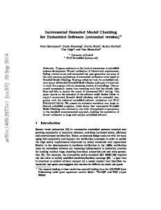
For the second part of the experiment, CFCSS is included in the assembly source code and the branch fault (branch deletion, branch creation, and operand change) is inserted into the code. The resulting assembly code is compiled and executed. The result of 500 iteration is shown in Table 2. In this table, the last row is the number of faults that result in error and are not detected by either CFCSS technique or the operating system. The graph in Fig. 5.1 illustrates percentage of faults that are detected in both the original program and the program with CFCSS. CFCSS shows high error detection capability; on average 3.0% of injected faults in most programs produced incorrect outputs without being detected. On the other hand, the original programs without CFCSS produced undetected incorrect results that average 33.7% of the total faults. The simulation result shows that CFCSS increased the error detection capability in an order of magnitude. Table 2. Result of branch fault injection into the programs with CFCSS. Matrix
Quick
Insert
mul
sort
sort
34.4%
41.0%
28,8%
37.2%
34.6%
40.0%
0.8%
0%
2.4%
0.6%
0.6%
0.0%
1.6%
Infinite erroneous result
0.2%
2.8%
0%
0%
0%
0.2%
0%
Processor hung
1.0%
1.4%
0.6%
2.8%
3.4%
1.6%
1.6%
Detected by OS
12.0%
13.6%
9.4%
17.4%
11.0%
8.0%
7.2%
Correct result
55.2%
47.8%
46.6%
50.4%
47.8%
55.6%
49.6%
Total
100%
100%
100%
100%
100%
100%
100%
Fault not secured
1.8%
4.2%
3.0%
3.4%
4.0%
1.8%
3.2%
LZW
FFT
30.8%
Incorrect result
Detected by CFCSS
16
Hanoi
Shuffle
Fault not detected 50.00%
45.40%
45.00% 39.60%
40.00% 33.60%
35.00% 30.00%
26.20%
25.00% 20.00% 15.00% 10.00% 3.40%
4.20%
5.00%
4.00%
1.80%
0.00% Lzw
FFT
Quick sort
Without CFCSS
Insert sort
With CFCSS
Fig. 5.1. Percentage of faults not detected Table 3 shows the overhead of CFCSS in selected sample programs.
The second
column indicates the number of instructions before adding checking instructions to the original program. The third column shows the number of checking instructions added and the fourth column is the number of basic blocks in the program. The last column shows us the overhead of adding the checking instructions to the original program, i.e., the ratio of checking instructions over normal instructions.
Table 3. Checking instruction overhead. Program
Instructions
Checking Inst.
Basic blocks
Overhead
FFT
411
140
47
34 %
adder_check
426
138
66
32 %
hash_table
1149
376
199
32 %
binary_tree
3330
1643
559
49 %
external_sort
1430
776
280
54 %
symbol_table
393
224
91
56 %
quick_sort
254
142
47
56 %
counter
40
19
9
47 %
lzw
452
280
105
61 %
insert_sort
132
84
29
64 %
simple_sort
191
130
41
68 %
The calculation intensive programs, such as FFT, have larger size basic blocks than data analysis programs. Thus the overhead is smaller for these programs (around 30% for FFT). 17
On the other hand, programs such as sorting and searching have small size basic blocks because they have frequent branch instructions.
Therefore, the overhead of checking
instructions in these programs is relatively high compared to calculation intensive programs.
6. OVERHEAD REDUCTION AND EXAMPLES When we consider the overhead of Algorithm A, each node has between 2 to 4 additional instructions. If we assume that the average size of one basic block is 7 to 8 instructions [Hennessy 96], the overhead is around 25% to 43% (all the overheads discussed in this report are static overheads). As we saw, every node has one instruction that compares the run-time signature with the signature of that node. If it is not critical to detect an error immediately, in other words, if we allow a longer latency for detecting an error, we can postpone the comparison of the signatures. Once an illegal branch is taken and the run-time signature becomes unequal to the signature of the node, the run-time signature will never match the signatures of the following nodes in the control flow because all signatures are different in the program graph. Therefore, we can put the comparison instruction only in some of the nodes and detect the mismatch of the signatures in those nodes after an illegal branch. Algorithm B describes the technique to reduce overhead in Algorithm A by postponing the comparison. The difference between Algorithm A and Algorithm B is in step 3.6. Instead of comparing signatures at every node, Algorithm B compares the signatures at the node where we want to detect the control flow error. Algorithm B. 1. Identify all basic blocks, build program flow graph and number all nodes in the program flow graph. 2. Assign a signature si to node vi in which si ≠ sj if i ≠ j, i,j = 1,2,...,N, N is the total number of nodes in the program. 3.For each node vj, j = 1,2,…,N. 1) For node vj whose pred(vj) is only one node vi, the signature difference dj is calculated as dj = si ⊕ sj. 2) Insert an instruction G = G ⊕ dj into node vj. 3) For node vj whose pred(vj) is a set of nodes vi1,vi2,...,viM – therefore, vj is a branchfan-in node − the signature difference is determined by one of the nodes (picked arbitrarily) as d j = si1 ⊕ sj. For node vim, m = 1,2,...,M, the run-time adjusting signature Dim is set to Dim = si1 ⊕ sim. 4) Insert a instruction G = G ⊕ D im into node vim. 5) Insert a instruction G = G ⊕ D into node vj 18
6) Insert an instruction br (G≠s j) error only into node vj where the comparison between the run-time signature G = Gi and the signature si is wanted. Figure 5.1 shows two examples of Algorithm B.
V1
V1
V2
V2
V3
V7 V3
V4
V8
V4 V5
V5
V6
V6 Check node
Check node
(a)
(b)
Fig. 6.1. Two examples of Algorithm B
G = G ⊕ dk
I1 I2 . . . In
Normal node
G = G ⊕ dk D = si ⊕ sj
G = G ⊕ dk G = G ⊕D
I1 I2 . . . In
I1 I2 . . . In
Node prior to branch-fan-in node
Branch-fan-in node
G = G ⊕ dk br G≠s1 error
I1 I2 . . . In
Check node (not branch-fan-in)
Fig. 6.2. Checking instructions in Algorithm B In Fig. 6.1 (a), the run-time signature and the signature of node are compared only at node v6. The overhead for node v1, v2, v3 and v7 is only the signature generation function f(G, d). 19
The branch-fan-in node v5 has two instructions for f( f(G, d), D). Node v4 and v8 that are branching to the branch-fan-in node have two instructions: one for signature function and the other for loading D. Algorithm A has an overhead of 30% in Fig. 5.1 (a) assuming that all basic blocks have 8 instructions. If we apply Algorithm B to the same example, the overhead is 19%. Fig. 6.1 (b) shows an example of a loop in which the signature is checked only at the end of the loop instead of checking it at every node in the loop. Similarly as in Fig. 6.1 (a), only node v6 has br (G≠s) error instruction. The overhead of applying Algorithm A to this loop example is 37.5%. When Algorithm B is applied, the overhead is 27%. Fig. 6.2 shows four different nodes with associated checking instructions. A check node is a node that has the comparison instruction br (G≠s) error. The comparison instruction is excluded from the node that is not a check node. Note that a node can be a combination of these type, e.g., a branch-fan-in and check node.
7. SUMMARY This paper presents the Control Flow Checking by Software Signatures (CFCSS), a new signature monitoring technique for control flow checking using a pure software approach. CFCSS employs a run-time signature G and a run-time adjusting signature D to check the control flow of a program.
Algorithm A detects the inter-block control flow errors by
assigning a different signature to each node in the program graph.
The XOR operation is
used both to embed the signatures in the program and to check for them during run-time. In addition, the aliasing problem that may cause an undetectable illegal branch is discussed and the technique to avoid it is presented. Furthermore, Algorithm B is proposed to reduce the overhead by postponing the comparison of signatures. The distinctive feature of the CFCSS over previous signature monitoring techniques is that the CFCSS needs no dedicated hardware such as a watchdog processor for control flow checking. Watchdog task in multi-tasking environment also needs no extra hardware but the advantage of the CFCSS over it is that CFCSS can be used even when the operating system does not support multi-tasking.
If the hardware is fixed or a system is to be built using
commercial-off-the-shelf components to keep the costs low, and control flow checking is needed, CFCSS can be used to enhance the reliability of the system.
8. REFERENCES [Andrews 79] Andrews, D., “Using executable assertions for testing and fault tolerance,” 9th Fault-Tolerance Computing Symp., Madison, WI, June 20-22, 1979. 20
[Caldwell 97] Caldwell, D. W. and D. A. Rennels, “A Minimalist Hardware Architecture for Using Commercial Microcontrollers In Space,” 16th Digital Avionics Systems Conference, Oct. 28-30, 1997. [Eifert 84] Eifert, J. B. and J. P. Shen, “Processor Monitoring Using Asynchronous Signatured Instruction Streams,” Digest of Papers, 14th Annual Int’l Conf. on FaultTolerant Computing, pp. 394-399, June 1984. [Ersoz 85] Ersoz, A., D. M. Andrews, and E. J. McCluskey, “The Watchdog Task: Concurrent Error Detection Using Assertions,” Stanford University, Center for Reliable Computing, TR 85-8. [Furtado 96] Furtado, P., H. Madeira, “Fault Injection Evaluation of Assigned Signatures in RISC Processors,” Proc., Second European Dependable Computing Conference, Taormina, Italy, pp. 55-72, October 1996. [Hennessy 96] Hennessy, J. L. and D. A. Patterson, Computer Architecture: A Quantitative Approach, Second edition, 1996. [Ignatushchenko 94] Ignatushchenko, V. V., et al., “Effectiveness of temporal redundancy of parallel computational processes,” Automation and Remote Control, Vol. 55, No. 6, pt. 2, pp. 900-911, June 1994. [Lu 80] Lu, D. J., “Watchdog Processors and VLSI,” Proceedings of the National Electronics conference, Vol. 34, pp. 240-245, Chicago, Illinois, October 27-28, June 1980. [Lu 82] Lu, D. J., “Watchdog Processor and Structural Integrity Checking,” IEEE Transactions on Computers, vol. C-31, No. 7, pp. 681-685, July 1982. [Madeira 92] Madeira, H. and J. G. Silvia, “On-line Signature Learning and Checking,” Dependable Computing for Critical Applications 2, Springer-Verlag, J. F. and R. D. Schlichting (eds), pp. 395-420, 1992. [Madeira 93] Madeira, H., M. Rela, and J. G. Silvia, “Time Behavior Monitoring as an Error Detection Mechanism,” Dependable Computing for Critical Applications 2, SpringerVerlag, J. F. and R. D. Schlichting (eds), pp. 395-420, Feb. 1993. [Mahmood 85] Mahmood, Aamer and E. J. McCluskey, “Watchdog Processor: Error Coverage and Overhead,” Digest, The Fifteenth Annual Int’l Symposium on FaultTolerant Computing (FTCS-15), pp. 214-219, Ann Arbor, Michigan, June 19-21, 1985. [Miremadi 92] Miremadi, G., J. Karlsson, J. U. Gunneflo, and J. Torin, “Two Software Techniques for On-line Error Detection,” Digest of Papers, 22nd Annual Int’l Symo. on Fault_Tolerant Computing, pp. 328-335, July 1992. [Namjoo 82] Namjoo, M., “Techniques for Concurrent Testing of VLSI Processor Operation,” Digest of Papers, IEEE Test Conf., pp. 461-468, Nov. 1982.
21
[Ohlsson 95] J. Ohlsson and M Rimen, “Implicit Signature Checking,” Digest of Papers, Twenty-Fifth International symposium on Fault-Tolerant Computing, pp. 218-227, June 1995. [Saxena 90] Saxena, N. R., and E. J. McCluskey, “Control-Flow Checking Using Watchdog Assists and Extended-Precision Checksums,” IEEE Trans. on Computers, Vol. 39, No. 4, pp. 554-559, April 1990. [Shen 83] Shen, J. P. and M. A. Schuette, “On-line Self-Monitoring Using Signatured Instruction Streams,” Int’l Test Conf. proceedings, pp. 275-282, Oct. 1983 [Tung 90] C. H. Tung and C. W. McCarron, “Concurrent Control Flow Checking in Sequential and Parallel Program,” Twenty-Fourth Asilomar Conference on Signals, Systems and Computers, Maple Press, Vol. 2, pp. 851-855, Nov. 1990. [Wilken 89] Wilken, K., and J.P. Shen, “Concurrent Error Detection Using Signature Monitoring and Encryption: Low-Cost Concurrent-Detection of Processor Control Errors,” Dependable Computing for Critical Applications, Springer-Verlag, A. Avizienis, J.C. Laprie (eds), Vol. 4, pp. 365-384, 1989. [Wilken 90] Wilken, K. and J. P. Shen, “Continuous Signature Monitoring: Low-Cost Concurrent-Detection of Processor Control Errors,” IEEE Trans. on Computer Aided Design, Vol. 9, No. 6, pp. 629-641, June 1990. [Yau 80] Yau, S. S. and Fu-Chung Chen, “An Approach to Concurrent Control Flow Checking,” IEEE Trans. on Software Engineering, Vol. SE-6, No. 2, March 1980
22