... the floors to resist lateral loads. ⢠Loads in perpendicular direction are resisted through cross wall placed in orthogonal direction. Burj Dubai, Schematic Plan ...
Design of Tall Buildings: Trends and Achievements for Structural Performance November 7-11, 2016 Bangkok-Thailand
Naveed Anwar, PhD
Dr. Naveed Anwar
Conceptual Design in Structural System Development
The Tussle Can design be based on “Engineering Judgment” and “Intuition” Or It must be controlled by explicit computations and, restrictive limits and fully rational approaches
Dr. Naveed Anwar
2
It is by logic we prove, but by intuition we discover
Dr. Naveed Anwar
3
What a Structural Engineer Says !
Hardy Cross, 1885-1959
Dr. Naveed Anwar
4
Structural Engineers are “trained” to follow the procedures and equations and rules and be conformists
Whereas Architects are encouraged to dream and be “defiant” Dr. Naveed Anwar
5
Determine the wall thickness and reinforcement (6x2x3m)
Most structural engineer should be able to do Dr. Naveed Anwar
Design the most cost effective water tank to hold 36 Cum of water
Most Structural Engineers would not know what to do (Will need a “Structural Designer”) 6
Design the most cost effective, beautiful, and amazing water tank to hold 36 Cum of water
Performance + Cost + Aesthetes Dr. Naveed Anwar
Will need “Structural Artist” 7
Structural Engineering and Art • Structural Engineering in Art • Application of structural engineering in creating works of art in architecture and sculpture • Art of Structural Engineering • Taking the structural design to the level of an Art
Dr. Naveed Anwar
8
The Rational Design Process
Architectural Requirements
Structural System Development
Preliminary Sizing, Modeling and Analysis
Response and Design Checks
Detailed Modeling, Analysis and Design
Performance Based Design
Can we speed up this part Dr. Naveed Anwar
9
Learning from Experience
Architectural Layout
Preliminary Sizing Modelling Analysis Design
Structural Response And Design
To make design preliminary decisions without explicit calculations Dr. Naveed Anwar
10
Learn From Experiance
A Master Thesis in AIT, based on the Tall Buildings designed by Sy^2 and PBD carried out by AIT Solutions
Dr. Naveed Anwar
11
Using Artificial Neural Networks
Dr. Naveed Anwar
12
Learn From Experience
Dr. Naveed Anwar
13
Methodology
Dr. Naveed Anwar
14
Using Trained Network for New Design or Quick Check
Dr. Naveed Anwar
15
Dr. Naveed Anwar
16
Dr. Naveed Anwar
17
A Swing Towards the AI • Rich Pictures • Analytical Hierarchy Process (AHP) • Artificial Neural Networks (ANN) • Genetic Algorithms (GA) • Expert Systems (ES)
• Fuzzy Logic • Deep Thinking • Big Data and Data Mining Dr. Naveed Anwar
18
The Role of Computers and Software • Initially, computers were used to program the procedure we had
• Now, we develop procedures that are suited for computing
Dr. Naveed Anwar
19
Historical Prospective • In nature, the structures of organisms differ according to their size. For example, the structure of a large animal such as an elephant is radically different from that of a dog or a mosquito. • However, in spite of these obvious differences, until about the middle of the seventeenth century, scientists believed that it was possible to build larger structures simply by duplicating the form and proportion of a smaller one. • The prevailing opinion was that if the ratios between structural elements in the larger structure were made identical to the ratios in the smaller structure, the two structures would behave in a similar manner. Dr. Naveed Anwar
20
4 Commandments of Tall Buildings Design 1. Resist overturning forces due to lateral loads by using vertical elements placed as far apart as possible from the geometric center of the building 2. Channel gravity loads to those vertical elements resisting overturning forces 3. Link these vertical elements together with shearresisting structural elements that experience a minimum of shear lag effects such that the entire perimeter of the building resists the overturning moments 4. Resist lateral forces with members axially loaded in compression rather than those loaded in tension due to overturning Dr. Naveed Anwar
21
A Quick Look at Structural Systems
Dr. Naveed Anwar
The Building Structural System - Conceptual Gravity Load Resisting System (GLRS) • The structural system (beams, slab, girders, columns, etc.) that act primarily to support the gravity or vertical loads
Lateral Load Resisting System (LLRS) • The structural system (columns, shear walls, bracing, etc.) that primarily acts to resist the lateral loads
Floor Diaphragm (FD) • The structural system that transfers lateral loads to the lateral load resisting system and provides in-plane floor stiffness Dr. Naveed Anwar
23
Vertical Load Resisting Systems Slabs supported on long rigid supports
Slab-system supported on small rigid supports Slabs supported on soil Dr. Naveed Anwar
• Supported on stiff beams or walls • One-way and two-way slabs • Main consideration is flexural reinforcement • Supported on columns directly • Flat slab floor systems • Main consideration is shear transfer, moment distribution in various parts and lateral load resistance
• Slabs on grade: light, uniformly distributed loads • Footings, mat, etc. Heavy concentrated loads
24
Lateral Load Bearing Systems PURPOSE • “To transfer lateral loads applied at any location in the structure down to the foundation level”
SINGLE SYSTEM 1. Moment Resisting Frames 3. Shear Walls
2. 4.
Braced Frames Tubular Systems
DUAL SYSTEMS and Multiple 1. Shear Walls-Frames 2. Tube + Frame + Shear Walls Dr. Naveed Anwar
25
Lateral Load Resisting Systems
Moment Resisting Frame Dr. Naveed Anwar
Shear Wall and FrameShear Wall – Frame Coupled 26
Lateral Load Resisting Systems
Braced Frame Dr. Naveed Anwar
Tubular Structure
Braced Tube Systems 27
Lateral Load Resisting System Frame System
Wall System
Tubular System
Rigid Frame
Couple Shear Walls
Tube Systems with Widely Spaced Columns
Frame with Haunch Girder
Core Supported Shear Walls
Frame Tube System
Flat Slab-Frame System
Spinal Wall System
Irregular Tubes
Outrigger and Belt Wall System
Exterior Diagonal Tube
Flat Slab Frame with Shear Wall
Bundled Tube
Dr. Naveed Anwar
Miscellaneous System
Steel Structure Systems
28
Wall Systems Dr. Naveed Anwar
Coupled Shear Walls • A system of interconnected shear walls exhibits a stiffness that far exceeds the summation of the individual wall stiffness. • The system is economical for buildings in the 40-story range as Walls behave as if they are connected through a continuous shear-resisting medium. • Placement of walls around elevators, stairs, and utility shafts is common because they do not interfere with interior architectural layout. • Resistance to torsional loads must be considered in determining their location.
Dr. Naveed Anwar
30
Coupled Shear Walls
Coupled Shear Walls
Dr. Naveed Anwar
Representation of coupled shear wall by continuum model: (a) Wall with openings, (b) Analytical model for close-form solution 31
Core-supported Structures •
Shear walls placed around building services such as elevators and stair cores can be considered as a spatial system capable of transmitting lateral loads in both directions.
•
The shape of the core is typically dictated by the elevator and stair requirements and can vary from a single rectangular core to multiple cores.
•
Floor framing around the core typically consists of systems such as castin-place mild steel reinforced or post tensioned concrete
Dr. Naveed Anwar
32
Core-supported Structures
Dr. Naveed Anwar
33
Core-supported Structures Full depth interior shear walls acting as giant K-brace. (a) Plan and (b) schematic section
Dr. Naveed Anwar
34
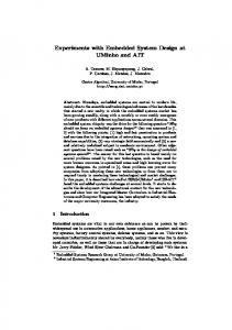
Spinal Wall System •
Well Suited for ultra tall residential towers
•
Shear walls are placed along both sides of corridor.
•
Spine walls run through the floors to resist lateral loads
•
Loads in perpendicular direction are resisted through cross wall placed in orthogonal direction
Dr. Naveed Anwar
Burj Dubai, Schematic Plan 35
Outrigger and Belt Wall System •
External moment is resisted through the combination of core and exterior columns connected through outriggers.
•
Effective depth of structure for resisting bending is increased when core flexes as vertical cantilever Outrigger and belt wall system with centrally located core Dr. Naveed Anwar
36
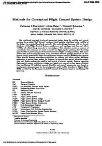
Optimum Location of a Single Outrigger Wall
Deflection index verses outrigger and belt wall location Dr. Naveed Anwar
Deflection index vs. belt wall and outrigger locations 37
Wall Systems - Flat Slab- frame with Shear Walls
Frame action from flat slab–beam and column interaction is generally insufficient to provide the required strength and stiffness for tall buildings A system of shear walls and flat slabframes may provide an appropriate lateral bracing system. Coupling of walls and columns solely by slabs is a relatively weak source of energy dissipation.
Dr. Naveed Anwar
38
Tubular Systems Dr. Naveed Anwar
Tube System with Widely Spaced Columns
Tube System with Widely Spaced Columns for 28-story building constructed in New Orleans Dr. Naveed Anwar
40
Frame Tube System
Frame Tube Building. (a) Schematic plan and (b) isometric view Dr. Naveed Anwar
41
From Frame to Tube
Tube
Dr. Naveed Anwar
Frame
42
Shear Lag Effects in Frame Tube System
(a) cantilever tube subjected to lateral loads, (b) shear stress distribution (c) distortion of flange element caused by shear stresses. Dr. Naveed Anwar
43
Irregular Tubes
Secondary frame action in an irregular tube; schematic axial forces in perimeter columns
Dr. Naveed Anwar
44
Exterior Diagonal Tube • Adding diagonal bracing improves the efficiency of frame tube in tall buildings by eliminating shear lag in flange and web frames. • Allows greater spacing between columns. • By applying structural principles, it is possible to visualize a concrete system consisting of closely spaced exterior columns with blocked-out windows at each floor to create a diagonal pattern on the building facade. • The diagonals carry lateral shear forces in axial compression and tension, thus eliminating bending in the columns and girders. Dr. Naveed Anwar
45
Bundled Tube
Dr. Naveed Anwar
46
Selection of Structural Systems
Dr. Naveed Anwar
Latest Techniques Genetic Algorithms (GA) Analytic Hierarchy Process (AHP)
Artificial Neural Networks (ANN)
Value Engineering
Fuzzy Logic
Linear/Nonlinear Programming Dr. Naveed Anwar
Expert Systems (ES) 48
Rich Pictures Try to consider as many factors as possible Take “Bird’s Eye” View Dr. Naveed Anwar
49
Knowledge Model for System Selection • Architecture • Building Services • Construction Engineering • Value Engineering • Aesthetics • Ergonomics Engineering • Structural Engineering • Knowledge Engineering
• Economics • Artificial Intelligence • System Engineering • Common Sense Dr. Naveed Anwar
50
Rich picture Diagram for System Selecteion
Dr. Naveed Anwar
A Master Thesis at AIT:
Sudiksha Amatya Naveed Anwar
51
Dr. Naveed Anwar
52
Rich Pictures Different professionals involved and their interrelationship with structural engineer during the selection of structural systems
Dr. Naveed Anwar
53
Structural System Suitability using AHP • The Analytical Hierarchy Process • A weighted importance and suitability value analysis to determine the comparative value of a system or option
n p Vl Ai Si Bij Sij Cijkl Sijk i 1 k 1 j 1 m
Value of an Option
Global Importance Weights and Scores Dr. Naveed Anwar
Sub Importance Weights and Scores
Suitability Value and Score
54
Evaluating System Suitability Using the Suitability Equation Criteria Weights and Scores Main Criteria Ai Sub Criteria Bij
Slab Systems
Item k
Am Sub Criteria Bin
Item p
Item k
Bmn
Item p
System Value (V)
Item
Wt
Score
Wt
Score
Wt
Score
Wt
Score
p Score
Cijkl
Sijkl
Cijnl
Sijpl
Cinkl
Sinkl
Cinnl
Sinpl
Smnpl
System – 1 System – l System - q Dr. Naveed Anwar
55
Assigning Suitability Values Score or Weight
Representation of Suitability
10
Most important, most suitable, most desirable, essential
8, 9
Very important, very suitable, very desirable
6, 7
Important, suitable or desirable
5
May be or could be important, suitable or desirable
3, 4
May not be important, suitable or desirable
1, 2
Not important, not suitable, not desirable
0 Dr. Naveed Anwar
Definitely not required, definitely not suitable, ignore 56
To do a Good Conceptual Design Develop the “Concept” at a higher level Identify the challenges and find solutions Compare value of alternatives Use previous experience
Be innovative, be defiant, think outside the box
Dr. Naveed Anwar
57
It is by logic we prove, but by intuition we discover
Dr. Naveed Anwar
58
Dr. Naveed Anwar
59