Pro-E. The actual design is based on the specifications best suited the prototype ... The PLC program shown in figure 14 explains the working of the motor for the ...
International Journal of Scientific & Engineering Research, Volume 4, Issue 7, July-2013 ISSN 2229-5518
1138
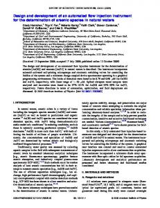
Conceptual Design and Development of Automated Drilling system Satyam Paul, Pawan Gupta, Milan Singh, Navmesh Singh Abstract— Involvement of automation in manufacturing technology plays an important role in enhancing the quality of process and products. An automated device which replaces manual involvement is an extraordinary contribution to the mankind. In this paper, stress is laid on the designing of an automated drilling system so to perform drilling operation automatically in efficient way. So for this purpose, initially the design of the drilling system setup is crafted using PRO-E software based on the design considerations. Then the actuation and control part is taken care with the help of actuating elements like DC motor, mechanical wheels and by programming it effectively using PLC. Finally the prototype model is developed in order to facilitate drilling operation with ease and accuracy. The drilling operation is performed by the combination of the movements of the drilling system and the base on which workpiece is kept for drill operations.In this paper innovative design and efficient programming have been merge to generate a device which will significantly contribute to the field of production. Index Terms— Automation, Manufacturing technology, Motors, PRO-E, Actuation, PLC, Drilling
—————————— ——————————
1 INTRODUCTION
I
n order to gain a competitive edge in today’s manufacturing market, astreamlined approach to the manufacturing process is required which focuses on increasing throughput while reducing or eliminating operator intervention. The most effective means for accomplishing this task is through machine automation. Automation is the use of computer to control industry machinery, replacing human operators. It is a step beyond mechanization, in which human operators are provided with machinery to help them in their jobs. It is a technology dealing with the application of mechatronics and computers for production of goods and services. A manufacturer’s primary consideration for automating a manufacturing system should be the machine tool and its control software. Advanced machine control software offers manufacturers the ability to dramatically reduce machine downtime, labor costs and human error. In the age of computers and innovative technologies, industrial automation is becoming increasingly important in the manufacturing process because computerized or robotic machines are capable of handling repetitive tasks quickly and efficiently. Machines used in industrial automation are also capable of completing mundane tasks that are not desirable to workers. In addition, the organization using automated machining technology can save money because it does not need to pay for expensive benefits for this specialized machinery.
The motion of one board with respect the other board and the cage structure respectively is controlled by incorporating rack and pinion system with DC geared electric motor as ashown in figure 1.
IJSER
2.2 Wheels and roller slides Wheels are used to give smooth motion by considering the moving base as roller slides.
Figure 2. Wheels It is easier to give motion to this type of system as minimal force is required to move the device on which the wheels are incorporated. The visual representation of the wheels and roller slides are shown in figure 2 and 3 respectively.
2 ACTUATING ELEMENTS FOR EFFICIENT MOTION 2.1 Rack and Pinion system
Figure 3. Slides Figure 1. Rack and Pinion
IJSER © 2013 http://www.ijser.org
International Journal of Scientific & Engineering Research, Volume 4, Issue 7, July-2013 ISSN 2229-5518
2.3 DC geared motor The main actuating elements for the motion control of the actual setup are DC geared motor. Three numbers of DC geared motor is been used for the control of three mechanism listed below:•Movement of Board A •Movement of Board B •Up and downward movement of the drill
1139
4 DESIGN CONSIDERATIONS The software used for the designing of the prototype model is Pro-E. The actual design is based on the specifications best suited the prototype model and has been laid down considering the following facts – •The design should be an effective one occupying less space. •The efficiency of the machine should be an appreciable one. •Easy operation. •Less power consumption.
Figure 4. DC Motor
Figure 6. Final Structure
IJSER
The main reasons for the selection of DC motor for control mechanism is that it has moderate horsepower and a wide range of speed selections. Apart from that, it has good efficiency, high life and requires very less maintenance
In figure 6, the design of the final prototype without the sliding components model is shown. It consists of cage structure having vertical support to hold the drilling system.
3 DRILLING SYSTEM SETUP
The circular slot provided at the joining junction of the vertical stand of the cage structure is utilised to fix the drill system. The upward and downward motion of the drilling system is managed with the help of rack and pinion system as show in figure 5. The shaft of the electric motor is attached to the central slot of the pinion. When the dc geared motor is switched on, the rotational motion of the shaft is converted into upward and downward motion of the drill system. Thus using a controller, the motion of drill system is controlled for drilling operation on the work piece.
Figure 5. Drill setup
Figure 7. Combination of two wooden boards In figure 7, two base structure having motion arrangements are mounted one over the other. The design of the structure is suitably drawn out for the best results. The components shown in figure 7 will be mounted on the base of cage structure for the final prototype design.
Figure 8 In figure 8 the methodology for the mechanical motion is depicted using PRO-E. The positions of the shaft, rack and pinion, wheels and electric motors are shown with accuracy and for the perfect operation of the setup efficiently and with greater accuracy. IJSER © 2013 http://www.ijser.org
International Journal of Scientific & Engineering Research, Volume 4, Issue 7, July-2013 ISSN 2229-5518
5 PROCESS INVOLVED A cage like structure containing the actual design is the base of the drilling system. The cage structure is a wooden frame having a circular slot at the centre. A spindle having an arrangement to move the drill up and down is fixed on the circular slot. The mechanical motion of all the parts associated within the design is taken care of with the help of actuating elements which is an electric motor. The upward and downward motion of the drill is controlled using electric motor. Inside the cage, there are two wooden boards fixed one above the other. The basic principle that will be used for the movement of the wooden boards is the combination of rack and pinion system as shown in figure with efficient incorporation of electric motors. The board (A) is fixed on board (B). The (X) side of the board (A) is placed on the (Y) side of the board (B). The rack fixed on the board (A)/ (X) side is placed on the pinion of board (B) to facilitate smooth movement of the board. The pinion is attached to the shaft of the board (B) .
1140
The motion of board (A) and board (B) are shown in figure 11 and figure 12 respectively. Both way arrowheads represents the sense of motion.
Figure 12
6 LADDER LOGIC PROGRAMMING A control panel is used to control the movement of the motor according to the need of driling. For each motor, three switches are used to activate and control the DC motor. Forward, backward and stop button is used for a single motor. Three motors with similar set of switches are used for the control mechanism of the entire system. The control panel is incorporated with a controller namely Programmable Logic Controller ( PLC) . Selec PLC kit as as shown in figure 13 is used for the control and motion of the all three DC motors. The software used for the programming of the sequential drive of the motor is ladder logic.
IJSER
Figure 9. (X) Side of the board (A)
The shaft will be rotated using electric motor as a result of which, the rotational movement of the shaft will be converted into the translational motion of the board (B). On the four edges of the board A, wheels are attached for free movement of the board (A) over board (B). Similar methodology is incorporated for the motion of board B over the cage structure.
Figure 13 Figure 10. (Y) side of the board (B) The material to be drilled will be placed on board (A). A controller will be utilised to control the motors associated with the board (A), board (B) and the drilling system.
Figure 11 In order to perform the drilling operations on the material, the movement of the board with respect to the drilling machine will be adjusted suitably so to achieve the final requirements.
The PLC program shown in figure 14 explains the working of the motor for the forward, reverse and stop position. The entire process involved for the motion of the DC motor has been divided into four stages. The stages of motion associated with the motor have been shown in the rungs. In the first rung, there are stop button and forward motion button. When the forward motion button is activated, the motor is energised and forward movement of the motor is actuated. So this operation is utilised for the specific movement of the device. Now if the forward motion button is released the motor will continue to rotate due to the latching circuit as shown in the second rung. Now in order to stop the motion of the motor, stop button is pressed which cuts-off the connection of the motor from the power supply. Now in order to achieve the motion of the
IJSER © 2013 http://www.ijser.org
International Journal of Scientific & Engineering Research, Volume 4, Issue 7, July-2013 ISSN 2229-5518
motor in the reverse direction, the reverse motion button is activated which will energises the motion of the motor in the reverse direction. Similar methodology is utilised for deactivating the motion of the motor. A latched circuit for reverse motion is shown in the fourth rung. Thus the motion of the motor in forward and reverse direction can be controlled continuously using the PLC kit and by programming it efficiently with the help of ladder logic.
1141
Actuating elements used for the mechanical movement are electric motors. Electric motors of desired specifications are attached to the board (A), board (B) and drilling system. The board (A), board (B) and cage are fabricated separately and then assembled properly. Thus a final prototype model as shown in figure 15 was developed which can be used significantly for automated drilling operations.
7 CONCLUSION In this paper stress is laid on the automation of drilling processes by blending innovative technology and by efficient programming with PLC. The new and conceptual design of automated drilling system is a remarkable approach towards a modern ternd in automation. This type of automated technology will favor the manufacturing industry in terms of cost, effectiveness and time.
REFERENCES [1]
IJSER [2]
[3]
Figure 14. PLC Ladder Logic .
Makoto Kikuchi, Masatake Shiraishi, “Possibility of Flexible and Automatic Drilling such as Human Work,” Proceedings of IEEE, International Conference of Mechatronics and Automation, Canada, July 2005. Øyvind Breyholtz, Gerhard Nygaard, and Michael Nikolaou*, “Automatic Control of Managed Pressure Drilling,” 2010 American Control Conference, June 30-July 02, 2010. Ben Zhang, Xiaoxia Luo, "Research on Drilling Section Automatic Generation Methods," Fifth International Symposium on Computational Intelligence and Design,2012 Qingjie Zhao, Fasheng Wang, Wei Wang, Hongbin Deng, "Adaptive Fuzzy Control Technology for Automatic Oil Drilling System," International Conference on Automation and Logistics, August 18 - 21, 2007, Jinan, China Bradley, Dawson et al., Mechatronics, Electronics in products and processes, Chapman and Hall Verlag, London, 1991. Tipler P.A., Mosca G., "Physics for Scientists and Engineers", Chapter 2 (5th edition), W. H. Freeman and company: New York and Basing stoke, 2003. Karnopp, Dean C., Donald L. Margolis, Ronald C. Rosenberg, System Dynamics: Modeling and Simulation of Mechatronic Systems, 4th Edition, Wiley, 2006.
[4]
6.3 Final Experimental Setup A final experimental setup of automated drilling system is shown in figure. Its consists of mainly three parts • Cage structure • Board A • Board
[5] [6] [7]
Figure 15. Final Model IJSER © 2013 http://www.ijser.org