Conceptual Model of the Graphical Editor G EN GE D for the Visual Definition of Visual Languages Roswitha Bardohl, Hartmut Ehrig Department of Computer Science Technical University Berlin, Germany frosi,
[email protected]
Abstract This contribution presents a conceptual model of G EN GE D, an editor supporting the visual definition of visual languages (VLs). A VL is defined by an alphabet and a grammar. These constituents are the input of a syntax-directed graphical editor allowing the manipulation of visual sentences over VL. The conceptual framework of G EN GE D is based on algebraic graph transformation and algebraic specification techniques. Starting with a type signature M ETA VISUAL for visual alphabets, the user of G EN GE D can define a specific VL-alphabet including graphical constraints. The VL-grammar definable on top of the VL-alphabet consists of a start sentence and a set of VL-rules. Each VL-rule is defined by a graph grammar rule in the sense of algebraic graph transformation. Keywords: visual definition of visual languages; generation of syntax-directed graphical editors; typed algebraic graph grammars.
1 Introduction Visual languages (VLs) are used within various application areas: teaching children and adults, programming for non-programmers, adaption of standard software to individual requirements, development of graphical user interfaces, etc. VLs are also used for software development, especially for the analysis and design of software systems. Well known examples of visual modelling and specification languages are UML, the Unified Modelling Language ([Cor98]), automata, Petri-nets and so on. All these languages can be supported by graphical tools. Common to all graphical tools is the fact, that they offer a VL instead of a textual one allowing the manipulation of visual sentences. But most of these tools do not allow the visual definition of a visual language. Of course, most of the graphical editors do not allow the definition of a VL; they are not intended to allow this, as they are tuned to a specific VL. Problems arise when graphical means of a VL are changed. Then, fixed implemented graphical editors must be redesigned and a reimplemented, leading to a time and cost intensive affair. Such problems are avoided by the G EN GE D environment. The G EN GE D environment supports the visual definition of VLs on the one hand and the generation of syntax-directed graphical editors for a defined VL on the other hand. Similar to textual languages a VL consists of an alphabet and a grammar, called
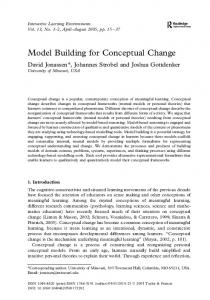
VL-alphabet and VL-grammar, respectively. In contrast to textual languages the alphabet of a VL is rather complex consisting of textual and graphical components. The VL-alphabet can be defined using an alphabet editor, whereas a grammar editor allows the definition of a VL-grammar based on the defined alphabet. A VL-grammar consists of one VL-sentence (the start graph) and a set of VL-rules (graph grammar rules). These VL-rules are the edit commands of a generated syntax-directed graphical editor allowing the correct manipulation of sentences wrt. the defined VL. The main components of G EN GE D are illustrated by Figure 1 (a). GENGED Class Alphabet Editor
VL-alphabet
Grammar Editor
VL-grammar
Graphical Editor
layout
Graph Transformation Machine
Graphical Constraint Solver
(a)
(b)
Figure 1 . G EN GE D-components (a) and one graphical symbol (b).
A VL-alphabet comprises graphical symbols and links between them. A graphical symbol consists of a name (type) and a graphic, both are connected by a layout operation. One graphical symbol for a class occuring in class diagrams (cf. [Cor98]) is presented in Figure 1 (b). Links between graphical symbols are defined by unary operations and graphical constraints. These constraints define equations between the layout of symbols. The alphabet definition results in an algebraic specification, called alphabet specification. Visual sentences occuring within a VL-grammar, that is the start graph as well as the constituents of a VL-rule, e.g., its left– and right-hand-side, are algebras wrt. the alphabet specification. The structure of a visual sentence is twofold: it consists of a logical level (the abstract syntax) and a visual level (the concrete syntax). Both levels are connected by layout operations. The manipulation of visual sentences is done by a graph transformation machine responsible for the logical level together with a graphical constraint solver which is responsible for the graphical layout. The first ideas towards G EN GE D are presented in [BT97] where algebraic specification techniques and graph grammars are used to describe VLs. Additionally it is briefly discussed which kind of editors may support the visual definition of VLs. Based on these ideas the first implementation of G EN GE D started in October 1997 within a student’s project where we gathered a lot of experiences 1 . These experiences are not only concerned with implementation issues but additionally with aspects of how to define a VL using G EN GE D. These topics are discussed in [Bar98]. Both articles, however, do not provide a conceptual model of G EN GE D based on typed algebraic signatures and meta-modelling. 1
The reimplementation of G EN GE D starting now, is partially supported by the German Research Council (DFG), the TMR network GETGRATS, and the ESPRIT Basic Research Working Group APPLIGRAPH.
In this contribution we present such a conceptual model of G EN GE D which uses concepts of algebraic graph transformation [EHK + 97], algebraic specifications [EM85] and typed algebraic graph signatures in analogy to typed graphs [CEL+ 96]. The paper is organized as follows: In Section 2 we present our conceptual algebraic framework for G EN GE D which is illustrated by an example of a visual alphabet. In Section 3 the alphabet editor is discussed wrt. to this example, i.e. it is shown which part of the alphabet is built up by the components of the alphabet editor. The visual grammar will be discussed in Section 4 together with the grammar editor and the generated graphical editor. Related work is presented in Section 5 and the conclusion in Section 6.
2 Conceptual Algebraic Framework The conceptual framework of the generic graphical editor G EN GE D is based on algebraic graph transformation (cf. [EHK + 97]) and algebraic specifications (cf. [EM85]). In this section we review the notion of algebraic graph signatures corresponding to graphs. In analogy to typed graphs (cf. [CEL+ 96]) they are extended to typed algebraic graph signatures (similar to [L¨ow97]) which are suitable for meta-modelling. This allows to formulate a meta-modelling concept on G EN GE D which is additionally explained in this section and which will be used in the subsequent sections. Typed Algebraic Graph Signatures. An algebraic graph signature S IG = (S, OP) with sort symbols S and operation symbols OP is a signature in the sense of algebraic specifications (cf. [EM85]) where all operation symbols are unary. This implies that an algebraic graph signature can be considered as a graph, where the vertices are the sorts and the edges are the operation symbols. Given an algebraic graph signature TS IG , called type signature, a typed algebraic TS IG ) is an algebraic graph signature S IG together with graph signature (S IG , t: S IG a signature morphism t: S IG TS IG , called type morphism. In this case S IG is called to be typed over TS IG . Since signature morphisms are closed under composition we immediately have
! !
Fact 2.1 (Transitivity of Typing) Given signatures S IG 1, S IG 2 and S IG 3 . If S IG 3 is typed over S IG 2 and S IG 2 is typed over S IG 1 then also S IG 3 is typed over S IG 1 . 4 Another important observation is the fact that each S IG -Algebra A for an algebraic graph signature S IG can be transformed into a signature T(A) typed over S IG : Fact 2.2 (Transformation of S IG-Algebras into Algebraic Graph Signatures ) Given an algebraic graph signature S IG and a S IG -algebra A we obtain a new algebraic graph signature T(A) typed over S IG as follows: If A consists of domains As (s 2 S ) and operations opA (op 2 OP ) for S IG = (S, OP) then T(A) consists of – sort symbols ST(A) defined by the disjoint union of all domains As (s 2 S ),
– operation symbols OPT(A) defined for ai 2 Asi , (i = 1; 2) by OPT(A) a1 ; a2 = f(op; a1 ; a2 ) j op 2 OPs1 ;s2 and opA (a1 ) = a2 g, – typing t(a) = s for a 2 As , s 2 S and t(op; a1 ; a2 ) = op.
4
Meta-Modelling Concepts on G EN GE D. The notions defined above form the basis for the meta-modelling concepts on G EN GE D (cf. Figure 2): Given M ETA VISUAL , a signature for VL-alphabets, the alphabet editor (cf. Figure 1) allows the user to define an algebra wrt. M ETA VISUAL and further constraints. The algebra will be transformed into a S IG -algebra, called alphabet signature, which is typed over M ETA VISUAL . Constraints which are used to link graphical symbols on the visual level are interpreted as equations, which yields an alphabet specification, called VL-alphabet. Visual sentences defined over the VL-alphabet are first of all algebras wrt. the VL-alphabet satisfying the equations. Again these algebras can be transformed into S IG -algebras, called sentence signature, which are typed over the alphabet signature. Because typing is transitiv visual sentences are also typed over M ETA VISUAL . Note, visual sentences occur in a VLgrammar as well as in VL-sentences which are derived by applying VL-grammar rules. MetaVisual t1
Alphabet Signature t2
Sentence Signature Figure 2 . Meta-modelling concepts on G EN GE D.
Definition 2.3 (M ETA VISUAL ) Let us regard the algebraic graph signature M ETA VISUAL which is implemented by G EN GE D: M ETA VISUAL = Graph Part
sorts V, E, ACV , ACE opns source, target: E opV : ACV V; E; opE : ACE
! !
Data Part
sorts Data
Attribution Part opns attrV : ACV attrE : ACE
! V;
! Data; ! Data;
Graphic Part
sorts Graphic
Layout Part
opns layoutV: V Graphic layoutE: E Graphic Graphic layoutACV : ACV layoutACE : ACE Graphic layoutData: Data Graphic
! !
! ! !
4
Example 2.4 (VL-Alphabet for Class Diagrams) An alphabet for a visual language VL in G EN GE D is defined to be an algebra of signature M ETA VISUAL . As specific example we consider a simple version of class diagrams (cf. [Cor98]) defining a visual language CD. The alphabet for CD is given by a M ETA VISUAL -algebra ACD . The algebra restricted to the graph part, for example, is given by ACD
=GraphP art
A = (ACD;V ; ACD;E ; AACV ; AACE ; sour eA ; targetA ; opA ; opE ) V
with the carrier sets ACD;V AACV
= fC D; C lassg, ACD;E = fI n l I n; Asso g, = fC N; AL; M Lg, AACE = fAN g,
and operations defined on the carrier sets: sour e sour e A
opV
A
A
(I n l
=
(Asso ) =
(AN ) =
A (C N ) E
op
I n)
=
C lass; target
C lass;
target
A
(I n l
A
(Asso ) =
I n)
=
C D;
C lass;
Asso ; op
A (AL) E
=
op
A (M L) E
=
C lass;
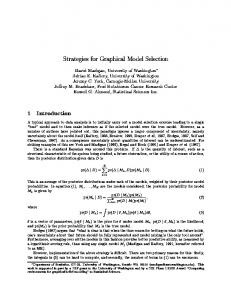
According to Fact 2.2 the algebra ACD is transformed into an algebraic graph signature T(ACD ). This signature with its sort and operation symbols is illustrated in the upper part of Figure 3. Note, the signature is typed over M ETA VISUAL ; the typing is not illustrated in this figure. Vertex and attribute carrier sorts are depicted by rectangles, edge sorts by ovals, and the operations are depicted by arrows. The sort symbol CD is used for a Class Diagram whose graphic should include all classes and associations. A class (Class) is defined together with its attributes, i.e. the attribute carriers together with the corresponding data types String and ListOfString (short LOS). These attributes are used for a class name (CN), an attribute list (AL), and a method list (ML). An association (Assoc) is attributed by an association name (AN). Associations connect classes; this is expressed by the source and target operations. Each graphical object shown in the lower part of Figure 3 is connected (dashed arrows) with an item of the logical level, i.e. an item of the graph part, data part or the attribute part wrt. M ETA VISUAL . These dashed lines respresent the layout operations. On top of the alphabet signature graphical constraints can be used to express the links between graphical objects according to the operations opV and opE wrt. M ETA VISUAL . The constraints, not shown in Figure 3, are equations and extend the alphabet signature V ISUAL S IG to an alphabet specification V ISUAL S PEC, called VL-alphabet for the language CD, in the sense of Definition 2.5.
4
Definition 2.5 (Alphabet Signature and VL-Alphabet) An alphabet signature for G EN GE D is an algebraic graph signature which is typed over M ETA VISUAL and denoted as V ISUAL S IG. A visual specification V ISUAL S PEC, called VL-alphabet, is an extension of V ISUAL S IG by equations expressing graphical constraints. 4
source Incl_In target
source
target
op V
CN
op attr V
op CD
Class
V AL opV
attrE String_AN
LOS_AL
attr V
ML
AN
Assoc
String_CN attr V
E
LOS_ML
PH
PH PH
PH
Text PH
List
List
Text
Figure 3 . Visualization of an alphabet signature for the visual language of class diagrams.
Visual sentences are algebras wrt. V ISUAL S PEC. They occur in VL-grammars as well as they are VL-sentences which are visual sentences derived by applying grammar productions. A visual sentence, for example, is an algebra consisting only of two class symbols; the other carrier sets are empty. Then, all operations are given by empty mappings. VL-grammars and the application of grammar productions are discussed in Section 4. However, according to Fact 2.2 visual sentences are transformed into sentence signatures, which are typed over the alphabet signature V ISUAL S IG. Definition 2.6 (Sentence Signature) A sentence signature for G EN GE D is an algebraic graph signature typed over V ISUAL S IG. V ISUAL S IG is again typed over M ETA VISUAL and because of transitivity of typing 4 also V ISUAL S IG is typed over M ETA VISUAL . The algebraic framework discussed above allows to formulate the following metamodelling concept for G EN GE D: Definition 2.7 (Meta-Modelling Concept) Step 1: Define a M ETA VISUAL -algebra A. By Fact 2.2 above we obtain an algebraic graph signature T(A), called V ISUAL S IG, which is typed over M ETA VISUAL . The alphabet signature V ISUAL S IG for G EN GE D is fixed for each visual language VL. Step 2: Each V ISUAL S IG-algebra AV L can be represented by Fact 2.2 as an algebraic graph signature T(AV L ) typed over V ISUAL S IG. By Fact 2.1 T(AV L ) is also typed over M ETA VISUAL .
4
Note, each V ISUAL S PEC algebra is additionally a V ISUAL S IG algebra (cf. [EM85]). The conceptual model of G EN GE D in the following sections is based on this metamodelling concept. Furthermore, in Section 3 we will extend the signature V ISUAL S IG to a specification V ISUAL S PEC using graphical constraints as discussed above, such that all visual sentences of a visual language VL become V ISUAL S PEC-algebras.
3 Visual Alphabet and Alphabet Editor The alphabet editor allows to define VL-alphabets. More precisely, we first consider an algebra A wrt. M ETA VISUAL . This algebra is transformed into a signature V ISUAL S IG, typed over M ETA VISUAL . Furthermore, as we will show in this section, the alphabet editor allows to define graphical constraints. These constraints are transformed into equations, such that V ISUAL S IG is extended to a visual specification V ISUAL S PEC which is the VL-alphabet established by using the alphabet editor. The alphabet editor consists of several components illustrated in Figure 4 and discussed below.
AlphabetEditor
Symbol Editor
Graphical Symbols
Connecting Editor
VL-alphabet
HLCs ConstraintHandling
LLCs
ParCon
Figure 4 . Components of the alphabet editor.
Symbol Editor. The symbol editor (SE) is an implementation of a fixed graphic algebra , i.e. SE allows the drawing of graphical objects as given in the lower part of Figure 3 for establishing graphical symbols. A graphical object consists either of one primitive object or of several primitive objects which are connected by graphical constraints. Graphical primitives are given by rectangles, circles, and in addition by place holders as “PH” in Figure 3. Such place holders can be used to denote a graph sort which should not be visible for further progress. Graphical objects are described by terms and defining equations. They are generic because of the position and the size. Not only the drawing of graphical objects is possible using the SE but additionally the definition of graph sorts typed over the graph part and data sorts typed over the data part of M ETA VISUAL . All these sorts have to be connected with a generic graphic constituting the layout definitions of V ISUAL S IG. Based on built-in data types for strings and lists of strings a specific data type for each VL is constructed leading to the data sorts of V ISUAL S IG. This yields a data signature DATA S IG and a corresponding algebra D. Corresponding data objects are represented graphically by “Text” resp. “List”. Altogether, the symbol editor provides a fixed graphic algebra G which is the implementation of a graphic signature G RAPHICS IG. It allows for each VL the establishment of specific graphical symbols as e.g. the symbol called CD in Figure 3 together with the layout operation and the graphic. G
Connecting Editor. The connecting editor (CE) allows to define the operations typed over the operations in the graph part and the attribution part of M ETA VISUAL . This definition is based on graphical symbols which are established using the symbol editor. In
the connecting editor all source and target operations, as well as attribution operations have to be defined visually (by selection) together with some layout constraints. These layout constraints are interpreted as equations over a V ISUAL S IG which yields an algebraic specification V ISUAL S PEC. We have to mention that usually we do not differ between common graphical symbols and data type symbols in the CE. Both are interpreted as graphical symbols, but a data type symbol can only be connected with a graphical symbol which represents a vertex or an edge. I.e. two data type symbols cannot be connected. Constraint Solver. The integrated graphical constraint solver PAR C ON [Gri96] works as a server. I.e. each editing area is a client of this server and gets its own solver incarnation. PAR C ON is implemented in Objective C, whereas all other components discussed in this paper are implemented in Java. The purpose of PAR C ON within G EN GE D is to solve the layout constraints for the construction of graphical objects. Constraint Handling. The constraint handling component offers a high-level constraint language. Each high-level constraint (HLC) will be translated into corresponding lowlevel constraints (LLC) the constraint solver PAR C ON works with. The predefined HLCs are collected within a library which can be seen as a super set of the constraint language used by PAR C ON2 . A HLC is e.g. given by “Rect1 Above Rect2”. Such a HLC is transformed into several LLCs PAR C ON works with; i.e., it is breaked down into several LLCs under consideration of the x,y coordinates and the height of the involved rectangles. Summing up, a VL-alphabet given by a visual specification V ISUAL S PEC is established when using the alphabet editor. This visual specification consists of – a visual signature V ISUAL S IG defined in Step 1 of the meta-modelling concept for G EN GE D, – a data signature DATA S IG built over the data part of V ISUAL S IG with fixed DATAS IG-algebra D for each visual language VL, – a graphic signature G RAPHICS IG built over the graphic part of V ISUAL S IG with a G RAPHICS IG-algebra G fixed within G EN GE D. This G RAPHICS IG-algebra G includes generic graphical objects g1 ; : : : ; gn of the graphic sort Graphi . These objects are specific for each visual language VL, – layout constraints for each operation of V ISUAL S IG’s graph and attribute part which yields equations extending V ISUAL S IG to V ISUAL S PEC. A V ISUAL S PEC-algebra A is then an algebra with a fixed interpretation D for the data part and G for the graphic part of V ISUAL S IG. All rules in the following section are built over V ISUAL S PEC-algebras and all visual sentences of each visual language VL become V ISUAL S PEC-algebras. 2
Surely, these predefined HLCs may not be sufficient to support all necessities for the definition of graphical symbols and their connections. Therefore, a user can extend the library by own constraints.
4 Visual Grammar, Grammar and Graphical Editor The grammar editor supports the definition of a VL-grammar, i.e. one visual sentence (the start graph) and a set of VL-rules. The edit commands of the grammar editor are alphabet rules automatically generated from the specification V ISUAL S PEC. The user defined VL-grammar will be the input of the generated graphical editor (cf. Figure 1) allowing the manipulation of VL-sentences by applying VL-rules. 4.1 Automatically Generated Alphabet Rules The grammar editor uses a concrete V ISUAL S PEC (the output of the alphabet editor) to generate specific rules, called alphabet rules. Alphabet rules are generated allowing the insertion and deletion of graphical symbols. The algorithm behind the generation of alphabet rules is based on V ISUAL S PEC, or more concretely, on the graph part of V I SUAL S PEC. Once established the logical level of a rule, the graph items are extended by the layout descriptions. According to insertion rules for each sort symbol of the graph part a rule is generated with an empty lhs. The rhs comprises the graphical symbol, i.e. the graph item which is equipped with its layout. In a second step the operations of the graph part are considered. Whenever a sort symbol occurs in the domain of an operation, both sides of the rule are extended by the codomain of this operation. I.e., the corresponding graphical symbols (logical item together with its layout) are put into both sides. Additionally, the corresponding operation is defined in the rhs, and the connection constraints are solved, such that both sides of the alphabet rule are algebras wrt. V ISUAL S PEC. Deletion rules are built up inverse to the insertion rules; i.e., both sides of the alphabet rules are exchanged, but in addition we need negative application conditions (cf. Section 4.2. Example 4.1 (Alphabet Rule) Given the alphabet signature of Example 2.4. Figure 5 illustrates a generated alphabet rule allowing the insertion of an association which was defined to be an edge. In this figure L (resp. R) denotes the lhs (resp. rhs) of the rule. Furthermore, the upper parts of the figure denote the logical level (the graph part of V ISUAL S PEC) which is connected by layout operations (dashed arrows) with the layout of each element. Because each side of the rule is an algebra wrt. V ISUAL S PEC it satisfies the equations. I.e., for each operation (source, target) at least one equation was established from the user defined constraint. We assume, that according to our example for the source (target) operation an equalPosition constraint is used to express that the association arrow begins (ends) at the east corner (west corner) of the class layout. These equations are satisfied in the rhs of the alphabet rule. Note, although some of the carrier sets are empty, both sides of the rule are algebras; the corresponding operations are then given by empty mappings.
4
Note, some of the automatically generated alphabet rules may express already intended VL-rules as one may think in the case of the alphabet rule presented in Figure 5. But sometimes it is useful to have more powerful VL-rules for editing VL-sentences in a generated graphical editor. The definition of VL-rules is supported by the grammar editor.
insertAssoc () 1:Class layout
2:Class
1:Class
layout
source
target
3:Assoc
2:Class
layout
layout
layout
::=
L
R
Figure 5 . Alphabet rule describing the insertion of an association.
4.2 Grammar Editor The grammar editor supports the definition of a VL-grammar by application of the automatically generated alphabet rules in a syntax-directed way. How a VL-grammar can be defined is explained along the components of the grammar editor illustrated in Figure 6.
GrammarEditor RuleManager AlphabetEditor VL-alphabet
Rule
RuleBuilder
RuleViewer MatchObject VL-grammar
ConstraintHandling
LLCs
ParCon
AGG
Figure 6 . Components of the Grammar Editor.
Rule Viewer. The RuleViewer supports the visualization of one rule. This rule can be one of the generated alphabet rules or one already constructed VL-rule. Furthermore, the rule viewer exports the objects which are selected by the user for a match. Rule Builder. The RuleBuilder allows the definition of VL-rules consisting of a lhs, a rhs and a morphism between items of both sides. I.e., the RuleBuilder consists of two working graphs, one for the lhs and one for the rhs of a VL-rule. It supports the application of one rule visualized by the RuleViewer in both sides. The application of rules is based on graph transformation implemented by the A GG-system ([Rud97,TER99]) and graphical constraint solving (cf. Section 4.3). This implies that each part of a VL-rule is an algebra wrt. V ISUAL S PEC in all actual working states. Rule Manager. The RuleManager is the main component of the grammar editor. It is responsible for all rules, i.e. for the alphabet rules and for the VL-rules. Especially, the rule manager generates the alphabet rules from the VL-alphabet.
AGG. The AGG-system (cf. [Rud97,TER99]) supports the graph transformation on the logical level of each algebra. The transformation is done using the single-pushout (SPO) approach as described in [EHK+ 97].
Constraint Handling and Constraint Solver. These components are already discussed in Section 3. Using the grammar editor for defining VL-rules means to allow the definition of rule names and rule parameters for certain data type values which is supported by the RuleManager. According to our alphabet rule of Figure 5 the VL-rule describing the insertion of an association would be named like insertAssoc(an: String) where an denotes the variable and String the data type. The visual level of this rule is illustrated in Figure 7.
insertAssoc (an: String) an
::= L
R
Figure 7 . Visual level of VL-rule describing the insertion of an association.
In the grammar editor we also have the possibility to define so-called negative application conditions (NAC) as proposed in [HHT96]. These NACs are bound by morphisms with the lhs of a rule. According to VLs such conditions allow to express that some situations must not occur when applying a VL-rule. This topic is mainly concerned with deletion rules, one is illustrated in Figure 8. It is required that the class symbol which should be deleted when applying the rule must not be connected with an association (arrow).
deleteClass () ::= NAC
L
R
Figure 8 . VL-rule describing the deletion of a class.
4.3 Graphical Editor The graphical editor allows the manipulation of visual sentences over a specific visual language VL defined by a VL-alphabet and a VL-grammar. According to Figure 1 it results from G EN GE D for a given VL. As for the grammar editor this manipulation is based on algebraic graph transformation and graphical constraint solving. The edit commands are the user-defined VL-rules which are correct in the sense of our framework, i.e. all sentences are algebras wrt. V ISUAL S PEC. The transformation of V ISUAL S PEC-algebras in G EN GE D is based on algebraic graph transformation [EHK+ 97], but there is no formal description of attribute and layout handling in G EN GE D up to now. This is due to the fact that we use implemented components, e.g. the AGG-attribute component [Mel99] and the graphical constraint solver PAR C ON [Gri96]. This means that the transformation of V ISUAL S PEC-algebras is done by the following steps: Step 1: Step 2: Step 3:
The graph part of V ISUAL S PEC-algebras A is transformed according to the SPO-approach which is implemented by the AGG-system. Attribute handling is done via Java in AGG. Layout handling is done via constraint solving supported by PAR C ON.
5 Related Work Many different formalisms have been proposed for the definition of VLs [MM96]. ¨ In contrast to existing approaches using either algebraic techniques [Usk94] or graph grammar approaches as presented by G¨ottler [G¨ot87], Andries, Engels, Rekers, Sch¨urr [Rek94,AER96] and Minas, Viehstaedt [Min93,MV95] our approach uses both for defining an alphabet and a language grammar. We use algebraic specification techniques to define graphical symbols, links and layout constraints in an axiomatic way. This seems to meet the definition of the very basic issues of a visual language in a natural way. The proper language, i.e. its grammatical structure, is described by graph transformation which is again a very natural formalism for this purpose. Many different tools just as formalisms have been proposed supporting the definition of VLs. In contrast to other approaches G EN GE D allows the explicit definition of alphabets and grammars for VLs. G.Costagliola et.all introduced the vlcc-environment [CDLOT97] supporting the visual definition of VLs, too. A symbol editor can be used to define terminal and non-terminal symbols. The defined symbols are then available within a production editor allowing the definition of context-free grammar rules. In contrast, we use algebraic graph grammars which are not restricted to be context-free. Furthermore, to be still in one formalism, we present automatically generated alphabet rules, which can be used for editing the VL-rules. In some cases these alphabet rules already define VL-rules, which are correct wrt. VL-alphabet. Nevertheless, vlcc offers not only a nice possibility to define VLs visually. Moreover, it generates free-hand editors for defined VLs.
6 Summary and Conclusions In this paper we have introduced a conceptual model of the graphical editor G EN GE D supporting the visual definition of VLs described by an algebraic framework. In this framework VLs are based on algebraic graph grammars. The manipulation of sentences is done by the graph transformation system A GG ([Rud97,TER99]) in connection with the graphical constraint solver PAR C ON ([Gri96]). G EN GE D can be used to define a great variety of VLs because it allows any kind of symbols and connections. Furthermore, G EN GE D offers a hybrid language where the visual sentences consist of graphical symbols as well as string sentences. These are the data attributes of nodes or edges. Moreover, the theory of algebraic graph transformation offers analysis techniques, for example for consistency checks. Consistency conditions concerning the existence and non-existence of graph parts can be proven for all graphs within a graph grammar produced language ([HW95,Wag97]). Using consistency conditions it is possible to ensure, e.g. that two classes do not have the same name. A first prototype of G EN GE D is realized within a student’s project which is the basis for the current (re)implemention of G EN GE D. The following extensions of the G EN GE D environment are planned: – – – –
Specification of application conditions. Specification of user interactions. Specification of the connection of several generated editors. Animation component which is useful for visual sentences modelling dynamical aspects such as firing in Petri-nets or automata.
References [AER96]
M. Andries, G. Engels, and J. Rekers. How to represent a Visual Program ? In [TVL96], 1996. [Bar98] R. Bardohl. G EN GE D - A Generic Graphical Editor for Visual Languages based on Algebraic Graph Grammars. In [VL’98], pages 48–55, 1998. [BT97] R. Bardohl and G. Taentzer. Defining Visual Languages by Algebraic Specification Techniques and Graph Grammars. In [TVL97], pages 27–42, 1997. [CDLOT97] G. Costagliola, A. De Lucia, S. Orefice, and G. Tortora. A Framework of Syntactic Models for the Implementation of Visual Languages. In [VL’97], pages 58–65, 1997. [CEL+ 96] A. Corradini, H. Ehrig, M. L¨owe, U. Montanari, and J. Padberg. The Category of Typed Graph Grammars and its Adjunctions with Categories of Derivations. In LNCS 1073 , Proc. Williamsburg, U.S.A., pages 56–74. Springer, 1996. [Cor98] Rational Software Corporation. UML – Unified Modeling Language. Technical report, Rational Software Corporation, http://www.rational.com, 1998. [EHK+ 97] H. Ehrig, R. Heckel, M. Korff, M. L¨owe, L. Ribeiro, A. Wagner, and A. Corradini. Algebraic Approaches to Graph Transformation II: Single Pushout Approach and Comparison with Double Pushout Approach. In G. Rozenberg, editor, The Handbook of Graph Grammars, Volume 1: Foundations. World Scientific, 1997.
[EM85]
[G¨ot87]
[Gri96] [HHT96] [HW95]
[L¨ow97] [Mel99] [Min93]
[MM96] [MV95] [Rek94]
[Roz99]
[Rud97] [TER99] [TVL96] [TVL97] ¨ [Usk94] [VL’94] [VL’95] [VL’97] [VL’98] [Wag97]
H. Ehrig and B. Mahr. Fundamentals of Algebraic Specifications 1: Equations and Initial Semantics, volume 6 of EACTS Monographs on Theoretical Computer Science. Springer, Berlin, 1985. H. G¨ottler. Graph Grammars and Diagram Editing. In H. Ehrig, M. Nagl, G. Rozenberg, and A. Rosenfeld, editors, Graph Grammars and Their Application to Computer Science, volume 291 of Lecture Notes in Computer Science, pages 216–231, 1987. P. Griebel. ParCon - Paralleles L¨osen von grafischen Constraints. PhD thesis, Paderborn University, February 1996. A. Habel, R. Heckel, and G. Taentzer. Graph Grammars with Negative Application Conditions. Special issue of Fundamenta Informaticae, 26(3,4), 1996. R. Heckel and A. Wagner. Ensuring Consistency of Conditional Graph Grammars – A constructive Approach. Proc. of SEGRAGRA’95 ”Graph Rewriting and Computation”, Electronic Notes of TCS, 2, 1995. http://www.elsevier.nl/locate/entcs/volume2.html. M. L¨owe. Evolution Patterns. Habilitation, TU-Berlin, 1997. also Technical Report No. 98–4. B. Melamed. Grundkonzeption und -implementierung einer Attributkomponente f¨ur ein Graphtransformationssystem. Diplomarbeit, Informatik, TU Berlin, 1999. M. Minas. Spezifikation von Diagrammeditoren mit automatischer Layoutanpassung. In H.Reichel, editor, Proc. 23. GI-Jahrestagung, Dresden, Reihe ’Informatik aktuell’, pages 334–339. GI, September 1993. K. Marriott and B. Meyer. Towards a Hierarchy of Visual Languages. In [TVL96], 1996. M. Minas and G. Viehstaedt. DiaGen: A Generator for Diagram Editors Providing Direct Manipulation and Execution of Diagrams. In [VL’95], 1995. J. Rekers. On the use of Graph Grammars for defining the Syntax of Graphical Languages. Technical Report tr94-11, Leiden University, Dep. of Computer Science, 1994. G. Rozenberg, editor. Handbook of Graph Grammars and Computing by Graph Transformaitons, Volume 2: Applications. World Scientific Publishing, 1999. to appear. M. Rudolf. Konzeption und Implementierung eines Interpreters f¨ur attributierte Graphtransformation. Diplomarbeit, Informatik, TU Berlin, 1997. G. Taentzer, C. Ermel, and M. Rudolf. The AGG Approach: Language and Tool Environment. In [Roz99]. Proc. of the AVI’96 Workshop Theory of Visual Languages, Gubbio, Italy, May 30. 1996. Proc. Workshop on Theory of Visual Languages, Capri, Italy, 27 September 1997. ¨ udarlı. Generating Visual Editors for Formally Specified Languages. In S.M. Usk¨ [VL’94], pages 278–285, 1994. Proc. Symp. on Visual Languages, St. Louis, Missouri, October, 4-7 1994. IEEE Computer Society Press. Proc. Symp. on Visual Languages, Darmstadt, Germany, September, 5-9 1995. IEEE Computer Society Press. Proc. Symp. on Visual Languages, Capri, Italy, September 1997. IEEE Computer Society Press. Proc. Symp. on Visual Languages, Halifax, Canada, September 1998. IEEE Computer Society Press. A. Wagner. A Formal Object Specification Technique Using Rule-Based Transformation of Partial Algebras. PhD thesis, TU Berlin, 1997.