Udit – A Graphical Editor For Task Models Gerrit Meixner
Marc Seissler
Marcel Nahler
German Research Center for Artificial Intelligence (DFKI) Trippstadter Str. 122 D-67663 Kaiserslautern +49 631 205-3707
University of Kaiserslautern Gottlieb-Daimler Str. D-67663 Kaiserslautern
University of Applied Sciences Trier Schneiderhof D-54293 Trier
[email protected]
[email protected]
[email protected] ABSTRACT Nowadays, the commercial success of an electronic device significantly depends on its usability. The demand for devices with intuitively usable interfaces is growing. This enforces developers to use user-centered development processes to guarantee a high usability for their product. The Useware Markup Language (useML) 2.0 is a user-centered task-oriented modeling language, which is used in the Useware-Engineering process for developing intelligent user interfaces. With version 2.0 some major changes have been made to increase the expressiveness of useML, i.e. with adding temporal operators the language has been equipped for semi-automatic dialog model generation. To support developers, an intuitively, graphical useML-Editor has been developed. This paper introduces the changes in useML 2.0, the useML-Editor and in part the transformation processes for deriving the dialog model from the use model.
Categories and Subject Descriptors H5.2 [Information Interfaces and Presentation]: User Interfaces, User-centered design; H.1.2 [Models and Principles]: User/Machine Systems
General Terms Design, Human Factors
Keywords Model-Based User Interface Development, MBUID, Usability, useML 2.0, Graphical Task-Model Editor, Udit
1. INTRODUCTION The improvement of human-machine-interaction is an important field of research reaching far back into the past. Yet, for almost two decades, Graphical User Interfaces (GUI’s) have dominated their interaction in most cases. In the future, a broader range of paradigms will emerge, allowing for multi-modal interaction incorporating, for example, visual, acoustic and haptic input and output in parallel [15]. But also the growing number of heterogeneous platforms and devices utilized complementarily— such as PC’s, smartphones, PDA’s etc.—demands for the development of congeneric user interfaces for a plethora of target platforms; their consistency ensures their intuitive use and their users’ satisfaction [5]. To meet the consistency requirement, factors such as reusability, flexibility, and platform-independence play an important role for the development of user interfaces. Further, the perseverative development effort for every single platform, single device or even single use context solution is way too high, so that a modelbased approach for the (abstract) development of user interfaces (MBUID) appears to be favourable [11]. The pivotal model of a
user-centric model-based development process is the task model [6]. Task models—developed during a user and use context analysis—are explicit representations of all user tasks [9]. Over the last years, various task-oriented modeling languages for designing user interfaces have been introduced. One of the main purposes of a task model in MBUID is to automatically generate user interfaces for different modalities and platforms. Due to this automatic generation, the development process must be improved by developing and using software tools regarding development time and usability. Section 2 describes the improvement of the Useware Markup Language 2.0. To support developers’, section 3 introduces a graphical useML-Editor. In section 4 we give a first review about our current transformation process for deriving dialog models from use models and in section 5 we conclude and give further outlooks.
2. USEWARE MARKUP LANGUAGE 2.0 While the basic structure of use models has not been changed since [8], certain enhancements have been incorporated into useML 2.0, which was originally developed in its first version for the definition of use structure of user interfaces in the field of production environments. According to [1], the use model must differentiate between interactive user tasks (performed via the user interface) and pure system tasks requiring no active intervention by the user. System tasks encapsulate tasks that are fulfilled solely by the system which, however, does not imply that no user interface must be presented, because the user might decide, for example, to abort the system task, or request information about the status of the system. Interactive tasks usually require the user(s) to actively operate the system, but still, there can be tasks that do not have to be fulfilled or may be tackled only under certain conditions. In any case, however, interactive tasks are usually connected to system tasks and the underlying application logic, which has been addressed recently by the newly introduced differentiation of user tasks and system tasks in useML 2.0. To specify that a certain task is optional, the semantics of use objects and elementary use objects has been enhanced to reflect their importance. Their respective user actions can now be marked as “optional”, “recommended”, or “required”. Similarly, only useML 2.0 is able to attribute cardinalities to use objects and elementary use objects. These cardinalities can specify minimum and maximum frequencies of utilization, ranging from 0 for optional tasks to ∞. Further, respective logical and/or temporal conditions can now be specified, as well as invariants that must be fulfilled at any time during the execution (processing) of a task. Invariants are especially needed for
defining security aspects, e.g. during interaction with industrial robots.
ensures, that saved projects are valid to the useML 2.0specification.
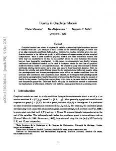
Consequently, temporal operators (see Fig. 1) have been added to useML, which is the most important and most comprehensive enhancement in version 2.0.
Figure 1: The enhanced useML 2.0
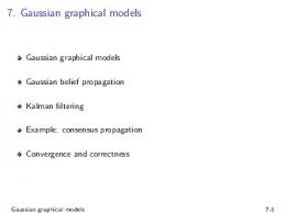
Figure 2: Screenshot of the graphical useML Editor
These operators allow for putting tasks within one hierarchical level into certain temporal orders explicitly; implicitly, temporal operators applied onto neighboring levels of the hierarchical structure can form highly complex, temporal expressions. In order to define the minimum number of temporal operators allowing for the broadest range of applications, other task modeling languages’ temporal operators were analyzed and compared. Among others, Tombola [13], XUAN [4] and CTT [10] were examined closely. Based on their temporal operators’ relevance and applicability in a model-based development process, the following binary temporal operators were selected for useML 2.0:
An integrated toolbar, located above the model-editor window (see Fig. 2), contains all essential functions for editing the structure of use models. Additionally to the toolbar, a contextsensitive menu, which can be accessed via a right click, lists all available functions, which can be performed on a selected object.
Choice (CHO): Exactly one of two tasks will be fulfilled.
Order Independence (IND): The two tasks can be accomplished in any arbitrary order. However, when the first task has been started, the second one has to wait for the first one to be finalized or aborted.
Concurrency (CON): The two tasks can be accomplished in any arbitrary order, even parallel at the same time (i.e. concurrently).
Sequence (SEQ): The tasks must be accomplished in the given order. The second task must wait until the first one has been fulfilled.
Since the unambiguous priority of these four temporal operators is crucial for the derivation of a dialog model from a use model, their priorities (i.e. order of temporal execution) have been defined as follows (see also [5]): Choice > Order Independence > Concurrency > Sequence.
3. UDIT – THE USEML EDITOR To improve the model-based development process, specialized tool support is required [1]. Therefore, a graphical useML-Editor (Udit), for editing useML 2.0-models, has been developed. Udit supports the whole expressiveness of useML 2.0 and allows users to edit any model consistent to the useML 2.0-specification. When starting a new useML-project, Udit creates a serialized useML-file, and a project-specific attributions style sheet file. Regardless, if the project has been loaded or created, Udit always
If a new elementary use object is added to the use model, a window, for editing the elementary use objects properties, automatically opens. This enables users to immediately set the elementary use objects information. A left double click on a use model, use object or elementary use object opens the properties window, too. To be ISO 9241-110 conforming, common properties are identically arranged in the properties window, which enhances the suitability for learning. Object-dependent properties, are grouped together by topic and placed in own tabs. Figure 3 shows the properties window for use objects.
Figure 3: Window for editing use object properties Udit displays the use model as a tree structure from left to right (see Fig. 2). The tree root, which represents the use model, is always located at the left window side and colored black. The direct successors of the root have to be, according to the useML specification, use objects. All siblings with same tree hierarchy share a column in Udit. Use objects are always colored orange. Each use object can be the father of a random number of use objects or elementary use objects. The elementary use objects also have a unique color representation. All elementary use objects which are interactive user tasks, like “Change”, “Release”, “Select” and “Enter” are colored green. “Inform”, which implies no direct user action is colored blue. To guarantee consistency of
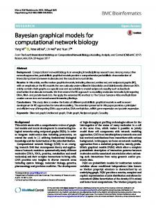
the information presentation, all use objects, elementary use objects and the use model have the same graphical structure. Due to the graphical representation of use models a better user experience should be guaranteed. In general, an object consists of a header, and a white label for its name. The object header consists of the abbreviated object-type and the unique object id, which is denoted in the upper right corner of the header. If the multiple execution-attribute of the use object is set, the number of iterations is enclosed by two brackets, placed before the objecttype. An asterisk, illustrated by the right use object in Fig. 4, represents infinite executions, which means, that the execution has to be aborted by the user. Temporal operators, which were introduced with useML 2.0 enable modeling temporal relationships between (elementary) use objects, are displayed as thin, vertical arrows. The type of the temporal operator, Sequence (SEQ), Concurrency (CON), Choice (CHO) or Order Independence (IND) is also denoted with a label in the middle of the arrow. Complex projects tend to a flood of information, which have to be managed by the developers. But usually only a small cut-set of these information, are relevant for handling the current task. To support them in focusing on important parts of the model, Udit implements various features, which support developers to set the granularity of the displayed models’ information. Via expand nodes the children of each use object can be displayed or hidden. This feature allows hiding sub-tasks, which are independent from the current task, for example. Additionally, Udit supports three different modes, for tailoring information of use objects. Figure 4 depicts those three detail levels for a use object. From left to right: “Simple view”-, “Show attributions”- and “Show all”representation. For the next update of Udit it is proposed to implement filters. This feature would allow filtering all use objects, which are available for a certain user group, for example. Besides editing use models, Udit also has an integrated style sheet-editor, which allows changing the project specific attributions style sheet. Those attributions are defined in a separate style sheet and can be adjusted to special project requirements. The “user group” element for example is such an attribution, which might vary in different (industrial) projects and therefore has to be adjustable. After saving the style sheet, developers can immediately use the new attribution values in the current project. For international use, Udit implements a multilingual designed interface. The application language can be easily changed via a simple language selection box, while the latest version of Udit is localized in German and English. Due to the .NET resource manager, it is easy to add new languages, if they'll be demanded in the future. Udit also supports exporting use models into various image formats, or to print them. These exports can be used for documentation purposes or for structural system evaluation. In the current version, Udit fulfills most of the specified requirements and is successfully used and tested in a large scale industrial project. Because of ongoing research progress, Udit is maintained to guarantee consistency to the useML specification and to increase the usability of the tool itself.
4. MODEL-MAPPING PROCESS In this section we want to give a first overview about our mapping approach from use models, specified with useML 2.0 into Abstract User Interfaces (AUIs). The underlying transformation
process is currently under research. Since useML 2.0 is a task modeling language it corresponds to the task & concepts layer of the CAMELEON Reference-Framework [2]. According to this framework the task & concepts models can be transformed into an Abstract User Interface (AUI). The AUI can further be decomposed into a presentation model and dialog model. While the presentation model specifies the structure of Abstract Interaction Objects (AIOs) [14] the dialog model is used for describing the interaction between the AIOs and the user [11]. The dialog model is also used to describe the navigation between the presentation sets of the UI [5]. Both models facilitate a platform and modality independent description of a user interface. The challenge finding an appropriate mapping between abstract and concrete models is also known as “the mapping problem” [11].
Figure 4: The three level of detail for use objects Our current mapping process is decomposed into the following steps: Task-user mappings: The task model can be tailored towards specific requirements. Filters enable developers to create a dialog model e.g. for a specific user group (Personalization) by removing tasks, which are not available on the target UI. Since filters can be specified for any type of assertion – e.g. user group –, the task model can be tailored in many different ways and is not limited to the user model. Task-dialog mappings: The task-dialog mapping is used to obtain the navigational structure of the task model [5]. This is expressed by the structure and temporal relationships between the tasks. Our approach is based on Enabled Task Sets (ETSs), introduced in [10]. An ETS is a set of tasks, which can be executed at the same time. Different algorithms have been presented, like in [10] and [3], to calculate these ETSs. Both use a top-down approach to identify the tasks, which share the same ETS. To specify the behavior, transitions are detected, which connect the ETSs with each other. Those transitions describe the “inter-window” relations as stated in [5]. Since we are interested in a more detailed dialog model, our approach could be considered as an “intra-window” [5] method, which describes the dialog within a “window”. This implies, that for each task in an ETS, a transition has to be generated, which is linked to another ETS. The linked ETS represents the tasks that can be executed, after the transitional task has been finished. Instead of separating the ETSs identification and finding the corresponding transitions, we use an algorithm – influenced by the simulator algorithm of CTTE [7] – which integrates the detection of ETSs and transitions: First, the algorithm identifies the initial ETS. This is done traversing the task model top-down, using a function which identifies the first tasks on each hierarchy, according to the semantics of the temporal operators. This function can be
compared to the “first”-function, used in [10], [3] and [5]. After the initial ETS has been identified, all tasks of the ETS are executed. When a task of an ETS is selected for execution, a new simulation cycle starts. The algorithm checks, which tasks of the task model have been executed – those are labeled “finished” – and which still can be executed. The tasks, which can be executed next – according to the temporal operators –, are grouped together within a new ETS. Then a new transition is created, labeled with the executed task, and linked to the new ETS. The last step is, to label the executed task as “finished”. This process is repeated, until all tasks of any ETS are executed, which implies that the root task of the task model is marked as “finished”. The whole dialog model can therefore be derived from the task model by generating all possible simulation traces. After the dialog model has been generated, it can be used to simulate the dynamical aspects of the task model, within a simulator. Simulation is important for the dynamic evaluation of use models.
[2] Calvary, G.; Coutaz, J. and Thevenin, D. et al. 2003. A Unifying Reference Framework for multi-target user interfaces. In: Interacting with Computers, 15(3):289-308.
Task-presentation mappings: With a task-presentation mapping, Abstract Interaction Objects (AIOs) are identified for each interactive user task in the task model. In case of useML 2.0 interactive user tasks are represented by elementary use objects. Since we are using the Dialog and Interface Specification Language (DISL) [12], a platform and modality independent UIDL, for AUI description, those elementary use objects have to be mapped onto corresponding generic widgets. A simple look-up table is used for this mapping. On this abstraction level, we don’t consider grouping of AIOs. This should be done within the concrete presentation model. The task model can be used to obtain information about how to group or organize the interaction Objects within a Concrete User Interface (CUI).
[6] Meixner, G. and Görlich, D. 2008. Aufgabenmodellierung als Kernelement eines nutzerzentrierten Entwicklungsprozesses für Bedienoberflächen. Workshop "Verhaltensmodellierung: Best Practices und neue Erkenntnisse", Fachtagung Modellierung.
The results of the dialog and presentation mappings can be used to generate an AUI, described with the DISL. Export functionalities will be integrated into Udit.
5. SUMMARY & OUTLOOK This paper introduced the major changes which have been incorporated into useML 2.0. With these changes, the expressiveness of useML has been strongly increased. The most important enhancement is the introduction of temporal operators. This also enables useML for a semi-automatic model transformation, into a dialog model. A preview of the transformation process we are using to transform useML models into DISL dialog models was first introduced in this paper. To support developers with a practical tool, the graphical use model editor Udit has been introduced. In the current version, useML has been successfully tested in a large project. With the help of a consistent color-schema, a well structured design and contextsensitive function-menus, the tool is designed to guaranty the best usability when editing use models. Further steps in the development of a MBUID tool chain will be the implementation of the introduced transformation processes for automatic derivation of dialog models from use models.
ACKNOWLEDGMENTS The work presented in this article is being supported in part by the Stiftung Rheinland-Pfalz für Innovation.
REFERENCES [1] Bomsdorf, B. and Szwillus, G. 1998. From task to dialogue: Task based user interface design. SIGCHI Bulletin, 30(4):4042.
[3] Coninx, K.; Luyten, K. and Vandervelpen, C. et al. 2003. Dygimes: Dynamically Generating Interfaces for Mobile Computing Devices and Embedded Systems. In: Proc. of the 5th International Symposium on Human-Computer Interaction with Mobile Devices and Services, 256-270. [4] Gray, P., England, D. and McGowan, S. 1994. XUAN: Enhancing UAN to capture temporal relationships among actions. Proc. of the Conference on People and Computers IX, Cambridge University Press, 301-312. [5] Luyten, K. 2004. Dynamic User Interface Generation for Mobile and Embedded Systems with Model-Based User Interface Development. PhD thesis, Transnationale Universiteit Limburg.
[7] Mori, G.; Paternò, F. and Santoro, C. 2002. CTTE: Support for Developing and Analyzing Task Models for Interactive System Design. In: IEEE Transactions on Software Engineering, 28(8): 797 – 813. [8] Mukasa, K. and Reuther, A. 2004. The Useware Markup Language (useML) – Development of user-centered Interfaces using XML. Proc. of the 9th IFAC/IFIPS/IFORS/IEA Symposium on Analysis, Design, and Evaluation of Human-Machine Systems. [9] Paris, C., Lu, S. and Vander Linden, K. 2003. Environments for the Construction and Use of Task Models. In: The Handbook of Task Analysis for Human-Computer Interaction, D. Diaper and N. Stanton (ed.), Lawrence Erlbaum Associates, 467-482. [10] Paternò, F. 1999. Model-based design and evaluation of interactive applications. Springer, London. [11] Puerta, A.; Eisenstein, J. 1999.: Towards a General Computational Framework for Model-Based Interface Development Systems. In: Proc. of the 4th international conference on Intelligent user interfaces, 171-178. [12] Schaefer, R.; Bleul, S. and Mueller, W. 2006. Dialog Modelling for Multiple Devices and Multiple Interaction Modalities. In: Proc. of the 5th International Workshop on Task Models and Diagrams for User Interface Design, 39-53. [13] Uhr, H. 2003. TOMBOLA: Simulation and User-Specific Presentation of Executable Task Models. Proc. of the International HCI Conference, 263-267. [14] Vanderdonckt, J.; Bodart, F. 1993.: Encapsulating Knowledge for Intelligent Automatic Interaction Objects Selection. In: Proc. of the 1st Annual CHI Conference on Human Factors in Computing Systems, 424-429. [15] Zuehlke, D. and Thiels, N. 2008. Useware-Engineering: a methodology for the development of user-friendly interfaces. Library Hi Tech, 26(1):126-140.