Smart Structures and Systems, Vol. 18, No. 3 (2016) 405-423 405
DOI: http://dx.doi.org/10.12989/sss.2016.18.3.405
Concrete pavement monitoring with PPP-BOTDA distributed strain and crack sensors 1
Yi Bao1, Fujian Tang1, Yizheng Chen1, Weina Meng1, Ying Huang2 and Genda Chen 1
Department of Civil, Architectural, and Environmental Engineering, Missouri University of Science and Technology, 1401 N. Pine Street, Rolla, MO 65409, USA. 2 Department of Civil and Environmental Engineering, North Dakota State University, 1410 N. 14th Avenue, Fargo, ND 58105, USA
(Received April 25, 2016, Revised June 22, 2016, Accepted July 12, 2016) Abstract. In this study, the feasibility of using telecommunication single-mode optical fiber (SMF) as a
distributed fiber optic strain and crack sensor was evaluated in concrete pavement monitoring. Tensile tests on various sensors indicated that the SMF-28e+ fiber revealed linear elastic behavior to rupture at approximately 26 N load and 2.6% strain. Six full-scale concrete panels were prepared and tested under truck and three-point loads to quantify the performance of sensors with pulse pre-pump Brillouin optical time domain analysis (PPP-BOTDA). The sensors were protected by precast mortar from brutal action during concrete casting. Once air-cured for 2 hours after initial setting, half a mortar cylinder of 12 mm in diameter ensured that the protected sensors remained functional during and after concrete casting. The strains measured from PPP-BOTDA with a sensitivity coefficient of 5.43×10⁻⁵ GHz/με were validated locally by commercial fiber Bragg grating (FBG) sensors. Unlike the point FBG sensors, the distributed PPP-BOTDA sensors can be utilized to effectively locate multiple cracks. Depending on their layout, the distributed sensors can provide one- or two-dimensional strain fields in pavement panels. The width of both micro and major cracks can be linearly related to the peak strain directly measured with the distributed fiber optic sensor. Keywords: concrete pavement; crack detection; distributed fiber optic sensor; strain distribution;
PPP-BOTDA
1. Introduction Unbonded Portland cement concrete (PCC) overlays have received increasing attention in new highway constructions and existing pavement rehabilitations (NCPTC 2007, Liao 2011, Burnham 2013). Thin PCC overlays have been cast on top of an existing pavement with a separation fabric layer to prevent the propagation of reflection cracking that has been observed in bonded concrete overlays (Liao 2011, Burnham 2013). However, thin PCC overlays can be more vulnerable to cracking than thick overlays due to reduced thickness and thus increased strain under the same vehicle load. Cracks can potentially accelerate the deterioration and reduce the service life of concrete (Raoufi 2010, Tang et al. 2016). Therefore, strain measurement and crack detection are Corresponding author, Professor, E-mail:
[email protected] Copyright © 2016 Techno-Press, Ltd. http://www.techno-press.org/?journal=sss&subpage=8
ISSN: 1738-1584 (Print), 1738-1991 (Online)
406
Yi Bao, Fujian Tang, Yizheng Chen, Weina Meng, Ying Huang and Genda Chen
critically important in the maintenance and management of over 4,000,000 km paved highway roads (Zhang et al. 2014, USDOT 2014). Point sensing technologies have been developed to monitor strain and cracking in concrete structures. For example, vibrating wires and fiber Bragg gratings (FBG) were embedded in concrete pavement to measure local strains and, by identifying sudden jumps in the strain measurements, perhaps detected one or more cracks when they happen to cross the sensors over their gauge length (Azenha et al. 2009, Lu and Xie 2007, Stephen 2012). Multiple FBG sensors were connected in series and multiplexed to increase the likelihood of crack detection with a quasi-distributed fiber optic sensor network (Zhao and Ansari 2001). Micro-electromechanical sensors and piezoelectric sensors were also embedded in pavement to measure localized temperature and strain (Ceylan et al. 2011, Lajnef et al. 2013, Xu et al. 2015, Alavi et al. 2016). In general, point sensors have three disadvantages: (i) low in success rate for the detection of unknown cracks, (ii) costly for a long distance deployment of highway roads, and (iii) inaccurate in strain measurement in thin pavement overlays, since the dimension of sensors is often comparable with the overlay‟s thickness, and thus can significantly influence the strain field. Distributed sensing technology may be advantageous over the point sensing technologies. For example, coaxial cable sensors were invented and successfully applied to measure strain distributions and detect a wide range of cracks from visually invisible to excessive corresponding to the failure of a full-scale reinforced concrete girder (Chen et al. 2005). However, coaxial cable sensors are presently unavailable in market and their measurement is potentially affected by passing vehicles on highways since the electromagnetic signals travelling in the cables are not immune to electromagnetic interference (EMI). Considering these constraints, distributed fiber optic sensors are likely a desirable choice for this application due to cost effectiveness, EMI immunity, and robustness in harsh environments (Bao and Chen 2012). Optical time domain reflectometry (OTDR) was used to detect multiple cracks in concrete based on Rayleigh scattering. In this case, the crack orientations must be known and their associated strains cannot be measured (Leung et al. 2000). Both Brillouin optical time domain analysis (BOTDA) with a loop measurement and Brillouin optical time domain reflectometry (BOTDR) with one end measurement were developed and applied to measure strain and temperature distributions over a long distance (Bao and Chen 2012). However, the spatial resolution of conventional BOTDA and BOTDR is generally low to detect multiple micro cracks (Wu et al. 2008). The best spatial resolution of 150 mm was reported by using a multiple peak fitting technique (Deif et al. 2010). A special installation of the sensor was applied to manipulate debonding between the optical fiber and the monitored host (Glisic and Inaudi 2011). The debonding resulted in an extra length to average the crack-induced length change in the optical fiber, which enables submillimeter cracks to be detected using BOTDA (Glisic and Inaudi 2011). Rayleigh scattering based technologies have also been implemented for distributed strain measurements with improved spatial resolution (Hoult et al. 2014). However, compared with stimulated Brillouin scattering technologies (e.g., BOTDA), the maximum sensing length is limited for Rayleigh scattering and spontaneous Brillouin scattering based technologies (Hoult et al. 2014). Recently, pulse pre-pump BOTDA or PPP-BOTDA was proposed to stimulate the phonon in optical fiber with a long-duration pulse before a short-duration pulse arrives, potentially achieving 20-mm spatial resolution (Kishida et al. 2005). In this study, telecommunication single-mode fibers (SMFs) are proposed and characterized as PPP-BOTDA distributed fiber optic sensors for strain measurement and crack detection. Their sensing performance (sensitivity, resolution, measurement distance) and practical limitations
Concrete pavement monitoring with PPP-BOTDA distributed strain and crack sensors
407
(susceptibility, strength, and deformability) are investigated for highway pavement applications. To this endeavor, a field-applicable sensor installation method is developed to protect optical fibers from damage during concrete casting. Six full-scale concrete panels were cast on a thin fabric sheet that represents a field application case in existing pavement rehabilitation. To quantify the ability of fiber optic sensors in operation and safety monitoring, each panel was tested under a dump truck first and then to failure under three-point loading. The peaks of a directly measured stain distribution can be used to evaluate the width and location of cracks and thus the performance of concrete panels.
2. Working principle of a PPP-BOTDA distributed fiber optic sensor Brillouin scattering in an optical fiber describes the interaction of a light wave (photon) with an acoustic wave (Kishida et al. 2005, Bao and Chen 2012). In the case of BOTDA, a pump pulse and a probe continuous wave are generated and propagated towards each other in an optical fiber. When their frequency difference matches with the Brillouin frequency of the optical fiber, Brillouin scattering is maximized with a significant gain or loss as a result of an amplified change of the medium density, which is referred to as simulated Brillouin scattering (SBS) (Bao and Chen 2012). In comparison with the BOTDA, PPP-BOTDA further stimulates the phonon with a long-duration pulse before a short-duration (narrow bandwidth) pulse arrives (Kishida et al. 2005). The pulse pre-pump can greatly improve the accuracy of Brillouin frequency identification, and thus improve the accuracy of strain and temperature measurement and spatial resolution of crack detection as discussed below. When an optical fiber is subjected to a variation of strain and/or temperature, the SBS spectrum is shifted with corresponding Brillouin frequency changed. The Brillouin frequency shift is on the order of 9–13 GHz for light with 1.3–1.6 μm wavelength in a standard SMF, and it can be calculated by (Bao and Chen 2012) B
2nVa
(1)
where n is the effective refractive index; Va is the acoustic wave velocity; and λ is the wavelength of the laser source. At normal temperature, ΔνB can be linearly related to the strain and/or temperature change (Bao and Chen 2012) B Cε CT T
(2)
where Δε and ΔT represent the strain and temperature changes with reference to their calibration conditions, respectively, and Cε and CT denote their respective coefficients. At high temperatures, nonlinear relationship should be used (Bao and Chen 2016a, b). The location of Brillouin backscattering along the length of an optical fiber can be determined by the time delay of arrival at the speed of light c. Therefore, the spatial resolution Δz can be defined as the location accuracy that can be calculated by (Bao and Chen 2012) z
where w denotes the pulse width.
wc 2n
(3)
408
Yi Bao, Fujian Tang, Yizheng Chen, Weina Meng, Ying Huang and Genda Chen
With a pulse of 0.2 ns width and an average count of 215, a 20 mm spatial resolution can be achieved with a 0.5 km measurement distance, a 15 με accuracy for strain measurement, and a 0.75 °C accuracy for temperature measurement using a Neubrescope (model: NBX-7020).
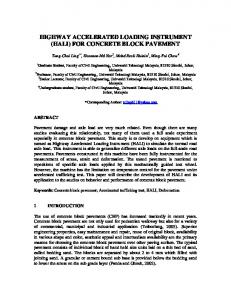
3. Characterization of optical fiber 3.1 Mechanical properties In this study, SMF-28e+ optical fiber as shown in Fig. 1(a) was used as a distributed fiber optic sensor, referred to as bare fiber (BF). It consists of a glass core (diameter: 8.2 μm), a glass cladding (outer diameter: 125 μm), and two layers of polymeric coating (outer diameter: 242 μm). The soft inner layer (outer diameter: 190 μm) protects the glass from mechanical impact, and the stiff outer layer protects the glass from abrasion and environmental exposure. Both layers are composed of complex mixtures of materials (Kouzmina et al. 2010). To understand the strength and deformability, ten optical fibers with a gage length of 250 mm were tested to rupture in tension at a displacement rate of 1 mm/min. Their mechanical properties were evaluated at room temperature (22°C). Considering the fragility of glass, each fiber was reinforced with protective sleeves at both ends where it is in direct contact with grips of a 5-kN load frame. The applied load was measured with a 100 N load cell. The applied load and the fiber elongation were simultaneously recorded so that the load-strain relation as shown in Fig. 1(b) can be obtained with the given initial gage length. The applied load increased linearly with strain up to approximately 26×103 με (2.6%) when the optical core and cladding ruptured shortly afterward, and then rapidly dropped from approximately 26 N to zero. The slope of the load-strain curve was determined to be 9.8×10⁻⁴ N/με. The tensile strengths and ultimate strains of the ten samples are respectively presented in Figs. 2(a) and 2(b). Their average tensile strength and average strain are 22.6 N and 23.3×10³ με, respectively. In Fig. 2, the coefficient of variation (Cv) is presented to quantify the variation of measured data.
(a) Cross section
(b) Load-strain curve
Fig. 1 Single-mode optical fiber with dual-layer coating
Concrete pavement monitoring with PPP-BOTDA distributed strain and crack sensors
(a) Tensile strength
409
(b) Tensile stain capacity Fig. 2 Tensile test results
(a) Test setup
(b) Strain sensitivity coefficient Fig. 3 Calibration of fiber optic sensors
3.2 Sensitivity calibration with PPP-BOTDA Another optical fiber was tested in tension under increasing loads as shown in Fig. 3(a). At each load, the strain in the optical fiber was simultaneously measured using the Neubrescope and the load frame. The Neubrescope measures the Brillouin frequency shift that can be converted into the strain change from Eq. (2) when the ambient temperature is kept constant. Given the initial length of the optical fiber, the strain values can be calculated from the elongation measurement by an extensometer of the load frame. Fig. 3(b) shows the directly measured Brillouin frequency shift as a function of the applied strain obtained from the load frame. The R2 value for the regression linear line is close to 1.0, indicating a good correlation. The slope of the line (= 5.43×10⁻⁵ GHz/με) represents the strain sensitivity coefficient.
410
Yi Bao, Fujian Tang, Yizheng Chen, Weina Meng, Ying Huang and Genda Chen
4. Sensor installation and full-size concrete panel fabrication To protect optical fibers from damage in construction, an optical fiber installation method was developed and implemented in the casting process of concrete panel. As illustrated in Fig. 4(a), an optical fiber was first attached on a 3 mm thick fabric sheet with adhesive at 20 cm spacing, then covered by a thin layer of mortar in half cylinder (6–12 mm in radius), and finally embedded into concrete during the panel casting. The mortar sunk into the porous fabric by approximately 1.5 mm as indicated in the scanning electron microscopy (SEM) image in Fig. 4(b). The sample was cut from the tested pavement panels, polished, and then dried at 80°C for 24 hours. Immediately prior to SEM imaging, the sample was coated with a very thin layer of gold for conduction. The magnification factor of the SEM image is 20x. The optical fiber is observed to be wetted well in the mortar, forming a good bonding interface. In this study, six 183 cm × 183 cm × 7.5 cm concrete panel specimens were reinforced with alloy polymer macro-synthetic fibers (Fibermesh 650). The mix designs of the concrete and the mortar are listed in Table 1. The average diameters of fine and coarse aggregates in concrete are 3.5 and 11.1 mm determined by sieve analysis (ASTM C136 2006). The initial setting time of the mortar was determined to be 90 min by ASTM standard test (ASTM C403/C403M 2008). A 3-mm thick fabric sheet was first laid on a 183 cm × 183 cm formwork. A bare optical fiber in loop was then attached on the fabric sheet in a specified pattern so that its ability for strain field measurement can be demonstrated. After the optical fiber was covered by mortar, concrete panels were cast and cured for testing. The panels were covered using wet burlap and plastic sheet for 1 day, and then air-cured for 28 days.
(a) Schematic view
(b) SEM image
Fig. 4 Optical fiber in mortar during concrete casting
Table 1 Mix deisgns of the concrete and mortar (unit: kg/m3) Type II Material
Class C fly
Water
Class C
Synthetic fiber
Super-plastici
aggregate
(40 mm)
zer
River sand cement
ash
Concrete
136
250
107
734
1064
3.57
1.78
Mortar
136
250
107
734
N.A.
N.A.
1.78
411
Concrete pavement monitoring with PPP-BOTDA distributed strain and crack sensors
Table 2 Installed fiber optic sensors in each concrete panel Sensors in each panel Concrete pour
First
Second
Panel
SMF-28e+ fiber
1D FBG sensor
3D FBG sensor
P1
BF01*, BF13
-
-
P4
BF03, BF15
FBG-1
-
P5
BF04, BF16
-
-
P2
BF07, BF08
FBG-2
-
P3
BF06, BF09
-
FBG-3
P6
BF05, BF18
-
FBG-4
*Italics font represents that the particular fiber optic sensor fails to work possibly due to damage during concrete casting or significant movement that causes acute angles of optical fiber, resulting in significant signal loss.
The six panels were designated as P1 to P6 in Table 2. They were cast in two pours: first Panels P1, P4, and P5 and then Panels P2, P3, and P6. Two bare fibers in 25 mm spacing were embedded in each of the six concrete panels as designated by BF01, BF03-BF09, BF13, BF15, BF16, and BF18 in Table 2. For comparison, FBG sensors were also deployed at the center of four panels. The first concrete pour began 30 min after mortar casting. Immediately after concrete pouring, measurements were taken from the optical fibers. As indicated in italics font in Table 2, BF01 in Panel P1, BF15 in Panel P4, and BF04 and BF16 in Panel P5 lost the optical fiber loops during the first concrete pour. This was mainly because the mortar was not hard enough to protect the optical fibers from local damage or prevent the fibers from significant macro-bending during concrete casting. Therefore, the second concrete pour started 2 hours after mortar casting. In this case, all the installed optical fibers survived the concrete casting process. Overall, the optical fiber protection method with mortar proved effective after initial setting of the mortar (90 min). To further quantify the protection level of mortar, free-fall impact tests were conducted on half mortar cylinders of various diameters and curing times. In each case, five fibers in U-shape were attached on a fabric sheet with adhesive as shown in Fig. 5. The fabric sheet was placed at the bottom of a 310 mm × 260 mm formwork in plan. Each optical fiber consists of two straight portions (220 mm each) and half a circle of 15 mm in radius. The 5 samples were placed side by side with even spacing of 30 mm. During each test, 0.005 m3 fresh concrete was poured into the center of the formwork out of a bucket at a height of 0.5 m so that the middle U-shaped fiber sample was subjected to most severe impact. The percentage of optical fibers that survived each impact test or survival rate (%) is presented in Table 3. The five optical fibers in loop all survived the impact test when their protective mortar cylinder was at least 6 mm in radius and was air-cured for at least initial setting time, which is 90 min. Since the results from six panels are in general agreement, only those from Panel P3 are presented, analyzed, and discussed in the following sections. Panel P3 was instrumented with two independent distributed fiber optic sensors named BF06 and BF09, respectively, and a FBG sensor.
412
Yi Bao, Fujian Tang, Yizheng Chen, Weina Meng, Ying Huang and Genda Chen
Fig. 5 Schematic view of optical fiber layout in free-fall impact tests (unit: mm)
Table 3 Optical fiber survival rate (%) with various mortar diameters and curing times Curing time (min) Cylinder radius (mm) 30
60
90
120
150
3-5
20%
40%
40%
60%
80%
6-10
40%
80%
80%
100%
100%
11-15
40%
60%
80%
100%
100%
5. Truck loading tests 5.1 Experimental program After 28-day curing, the concrete panels were laid on the strong floor and tested under truck loads as shown in Fig. 6(a). The dimensions of the truck are shown in Fig. 6(b). Two load levels were considered: empty and fully loaded. The weights of the front and back axes were respectively 4400 and 5200 kg for the empty truck and 6250 and 14,200 kg for the loaded truck. Fig. 7 shows the layout of distributed and FBG sensors as well as the positions of truck‟s tires on Panel P3. In this study, a U-shape distribution of distributed sensors is utilized to provide relatively detailed information on the strain and potential crack field of the pavement panel with one measurement. For easy reference, the curve portions of a looped optical fiber sensor were marked by A, B, …, L, M, and A. The multiple intersections between the distributed sensor and any crack were designated as “Ca-b”, where “C”, “a”, and “b” represent a crack, the crack number, and the intersection number of the crack with the sensor, respectively. All tests were conducted at room temperatre (22 °C) in the air-conditioned laboratory.
Concrete pavement monitoring with PPP-BOTDA distributed strain and crack sensors
(a) Truck on panels
413
(b) Dimensions of the dump truck (unit: cm) Fig. 6 Truck load test setup
Fig. 7 Sensor layout and three cracks in P3 under the fully loaded truck (unit: cm)
5.2 Results and discussion The Brillouin frequency shift of each panel was directly measured with the Neubrescope and converted into strain change according to equation (2). Figs. 8(a) and 8(b) show the strain distributions in BF06 and BF09, respectively, under the first pass and first stop (P1S1) of the dump truck. The horizontal axis represents the distance measured from the pulse end of an optical fiber, including both communication (dashed line in Fig. 7) and sensor (solid line in Fig. 7) portions. The strain distributions measured from BF06 and BF09 were in excellent agreement. The slight difference between them was due to the 25 mm separation distance between BF06 and BF09. At the distance of 24.5 m, two peaks (C2-2 and C1-1) were detected from the BF06 while only one peak (C2-1) was detected from the BF09. This was because the sensor portion of the BF09 was 0.3 m shorter than that of the BF06, and the first crack (C1) was not intercepted by the BF09 sensor. Due to uneven surface of the strong floor on which the test panel was placed, three cracks appeared in P3 under the fully loaded truck as indicated in Fig. 7. By comparing the strain distributions due to empty and fully-loaded trucks, as shown in Fig. 8(a), it can be observed that
414
Yi Bao, Fujian Tang, Yizheng Chen, Weina Meng, Ying Huang and Genda Chen
cracks due to the fully loaded truck can be detected from the sharp peaks such as C1-1 and C2-1 at the distance between 24 and 25 m. The sensor portion of an optical fiber in direct contact with concrete sensed the strain change in the panel. When the concrete panel cracked, the sensor passing through the crack would locally be elongated as reflected by a sharp peak in the measured strain distribution as illustrated in Fig. 8 (Bao et al. 2015). The crack can thus be detected at the location of the peak in a strain distribution as verified by measuring the physical position of the crack on the concrete panel. The crack width is likely correlated with the strain peak value. Spatial resolution is usually a critical issue for the detection of nearby cracks. In this study, two cracks with 0.1 m spacing were successfully distinguished as illustrated in Fig. 8(b). Therefore, a 0.1 m spatial resolution has been verified for crack detection although PPP-BOTDA can in theory provide 20 mm spatial resolution (Kishida et al. 2005, Neubrex Co. Ltd. 2013).
6. Three-point bending tests 6.1 Experimental setup After the truck load tests, Panel P3 was loaded to failure under a “three-point” bending setup as shown in Fig. 9. The reaction frame with a loading capacity of 445 kN was rigidly fixed on the strong floor and provided two reaction forces through two hydraulic actuators. The two reaction forces were transferred through two orthogonal rigid beams into a line load applied on each panel at its mid span. Each panel was simply supported on two steel rollers and beams, and loaded in displacement control with a rate of 2 mm/min.
(a) BF06
(b) BF09 Fig. 8 Strain distributions in Panel P3 under truck loads
Concrete pavement monitoring with PPP-BOTDA distributed strain and crack sensors
415
Fig. 9 Load frame test setup
The applied load was recorded by internal load cells in actuators with 10 Hz sampling rate. Mid-span deflections and support settlements were measured by linear variable differential transformers (LVDTs). The clear span length between supports was 1.5 m. The induced strains in the concrete panel were measured by the two distributed fiber optic sensors with the Neubrescope and by the FBG sensor with an optical spectrum interrogator (OSI, model: SM125). The measurement wavelength of the interrogator ranges from 1510 nm to 1590 nm. The measurement accuracy and repeatability are 1 pm (10-3 nm) and 0.5 pm, respectively. 6.2 Results and discussion Fig. 10 shows the load-deflection curves of Panel P3. The panel was loaded linearly with the applied deflection until a major crack appeared at 3.8 mm mid-span deflection. As a result of the concrete cracking, the load suddenly dropped from 21 to 8.8 kN and was then increased again with the deflection since the microfibers within the concrete matrix and the fabric sheet underneath the panel restrained the crack from widening. However, the overall slope of the load-deflection curve is smaller than that prior to the major crack, indicating a softening effect of the cracked panel. As the panel was further deflected, the microfibers gradually broke or were pulled out of the concrete matrix as observed during tests, resulting in a sudden load reduction approximately every 1–2 mm deflection increment. In this case, the load envelope except for local drops was relatively smooth. However, when part of the fabric was torn apart at mid-span deflections of 25 and 34 mm, the load drops were more significant than those due to microfiber breakage. The load remained to be approximately 8.9 kN at a mid-span deflection of 25 mm, and then gradually decreased to zero as the actuators extended 76 mm. After the panel failed in flexure and the bottom fabric sheet was removed, a major crack and several micro-cracks were located through tape measurements. As shown in Fig. 11, the major crack was approximately in the middle of span and intersected the two distributed sensors at the labeled locations (thick dash line in red) corresponding to strain peaks in Fig. 12. The micro-cracks represented by blue color in Fig. 11 were caused by truck loads.
416
Yi Bao, Fujian Tang, Yizheng Chen, Weina Meng, Ying Huang and Genda Chen
Fig. 10 Load-deflection curve of Panel P3
Fig. 11 Cracks in Panel P3 after load frame tests
At six different levels of mid-span deflection, the measured strains along a portion of the two distributed sensors from 5 to 16 m distance are presented in Figs. 12(a) and 12(b) from Sensors BF06 and BF09, respectively. At the same loading level, the measurements from BF06 and BF09 are correlated well. Similar to the strain distributions under truck load tests as shown in Figs. 8(a) and 8(b), cracks crossing a distributed sensor can be identified as sharp peaks in corresponding strain distribution (Feng et al. 2013). The crack locations in Fig. 11 were in excellent agreement with the locations of their corresponding peaks in Figs. 12(a) and 12(b). For example, the distance from the starting point of the BF06 to Peak 1 in Fig. 11 was approximately 6.56 m, including 5.64 m outside and 0.92 m inside Panel P3. Since it was 1.44 m away from Peak 1 along the BF06, Peak 2 could be identified at the distance of 8.00 m as verified in Fig. 12. The magnitude of multiple strain peaks corresponding to the same major crack varied to a certain degree since the strains were measured at different parts of the crack with potentially varying crack widths. It can
Concrete pavement monitoring with PPP-BOTDA distributed strain and crack sensors
417
be observed from Fig. 12 that the magnitude of each strain peak increased with the mid-span deflection as a result of crack widening. Due to bonding between the concrete and the optical fiber, the fiber passing through the crack was subjected to increased strain as the crack becomes widened.
7. Crack detectability 7.1 Visualization of crack distribution Based on the original U-shape optical fiber deployment scheme, the measured strain distribution along an optical fiber as shown in Fig. 12(a) or 12(b) can be re-produced into a two-dimensional (2D) strain field in the plane of the concrete panel as shown in Fig. 13. Since the two optical fibers are used to measure axial strains only, the 2D field is for one component of strain along many optical fiber segments that were deployed in parallel. The perspective view and the top view of the 2D strain field are plotted in Figs. 13(a) and 13(b), respectively.
(a) BF06
(b) BF09 Fig. 12 Strain distributions in Panel P3 in three-point bending test
418
Yi Bao, Fujian Tang, Yizheng Chen, Weina Meng, Ying Huang and Genda Chen
(a) Perspective view
(b) Top view
Fig. 13 Two-dimensional strain field in P3 at the mid-span deflection of 10 mm
Specifically, the parallel portion of the distributed BF06 sensor can be divided into eleven segments, each 1.6 m long, represented by A-B, B-C, C-D, …, and K-L as shown in Fig. 11. Each part is denoted by the “Length” axis in Fig. 13. The strain distributions in the eleven segments can be plotted in one figure with a separation distance in between according to the installation scheme of the optical fiber. The strain distributions in between every two of the eleven distributions are determined by linear interpolation. In this way, the strain field over the A-K-L-M area shown in Fig. 11 is determined as presented in Fig. 13. One advantage of the strain field in Fig. 13 over the 1D strain distribution in Fig. 12 is to enable an automatic identification of both orientation and length of cracks. For example, multiple cracks can be detected from the color-coded strain field. As shown in Fig. 13, the major crack corresponds to the largest strain represented by a red band and is located at the center of the red band. The microcracks can also be identified. 7.2 Considerations on crack width The red bands in Figs. 13(a) and 13(b) reflect the position of the major crack. However, the bandwidth is not equal to the crack width. As shown in Fig. 13(b), the bandwidth is approximately 190–200 mm while the crack width was measured to be 1.5–2.0 mm using a crackscope (model: CS-100, minimum scale: 50 μm). The broadening of bandwidth likely resulted from debonding between the glass cladding and the inner coating of optical fiber. The inner coating is made of soft material that is weak in shear strength. This ensures that the coatings can be easily stripped off the optical fiber for fiber splicing (Kouzmina et al. 2010). However, under a large strain gradient near crack faces, a significant shear strain is developed between coating layers of the optical fiber in order to transfer the normal concrete strain into the optical fiber, which can cause debonding in optical fiber (Li et al. 2003, Feng et al. 2013). The debonding length changes with the loading scenario and level. When the crack width is small, the debonding is insignificant. For example, C2-1 in Fig. 12 is sharper than Peak 1 since C2-1 corresponds to a microcrack whose crack width is smaller than that of the major crack. Debonding occurs only when cracks are widened and the bandwidth of peaks is visually observed to be broadened, as shown in Figs. 12(a) and 12(b). Regardless of debonding, the peak strain is
Concrete pavement monitoring with PPP-BOTDA distributed strain and crack sensors
419
associated with the crack width. This provides a way to estimate the width of a visible or hidden crack based on the measured strain distribution. Fig. 14 relates the width (w) of the major crack to the peak strain (Δεmax). Two linear equations were employed to fit the data before and after substantial debonding, respectively. For crack widths less than 100 μm when debonding in optical fiber was insignificant, the linear coefficient was determined to be 53.3 μm/με with R2 = 0.670. For crack widths exceeding 100 μm, significant debonding occurred and the crack-induced deformation in optical fiber would be averaged over the debonding length. Therefore, the same increase in crack width led to smaller changes in the peak strain. The linear coefficient was increased to 225 μm/με with R2 = 0.690. The two equations provided quantitative approximations for the crack width. Factors affecting the accuracy and repeatability of the prediction using the two equations included: (i) the crack widths were measured using the crackscope that had limited accuracy, since tiny cracks were difficult to read, and the crack faces were rough and uneven; and (ii) the strain measurements from the Neubrescope contained error. A better way to control and measure the crack width is needed to obtain a relationship between the crack width and the measured strain with higher accuracy and less variation. Fig. 14 reveals that the distributed sensor is sensitive to micro-scale cracks. In the quasi-static loading scenario, it demonstrated an operating range up to 3 mm before the fiber ruptured, which implied its feasibility in pavement applications. As to the concerns about the sensor‟s damage in engineering practice, after significant cracking occurs in a portion of pavement, the sensor can be repaired at the time when the pavement is rehabilitated. The sensor‟s break points can be detected using optical time domain reflectometry (OTDR) technology (Leung et al. 2000), and the break points can be fixed using fusion splice technique. 7.3 Comparison with FBG sensor The onset and widening of the major crack in P3 are illustrated in Fig. 15 on a cross section of the panel through the FBG sensor. The point FBG sensor is parallel to the distributed sensors BF06 and BF09. The major crack passed around the distributed sensors and the transmission cable of the FBG sensor. The transmission cable consisted of a single-mode optical fiber and a 1-mm thick steel cylindrical spiral that was coated with a 1-mm thick polyethylene.
Fig. 14 Correlation of crack width and peak strain
420
Yi Bao, Fujian Tang, Yizheng Chen, Weina Meng, Ying Huang and Genda Chen
(a) Onset of crack
(b) Widening of crack
Fig. 15 Development of the major crack in P3
The strains measured from the FBG sensor are compared in Fig. 16 with those from the BF06 after small temperature variation has been compensated. For this comparison, a point on the BF06 at 11.69 m distance is selected due to its proximity to the FBG sensor. The solid line and the dash line in Fig. 16 represent the measurements from the point FBG sensor and from the point of the distributed BF06 sensor, respectively. The induced strains in both sensors linearly increased till an applied mid-span deflection of 3.8 mm when the major crack occurred. When the panel was unloaded from approximately 6.35-mm to zero mid-span deflection, the measured strain differed from the original value because of the permanent damage. To quantify the relative difference between the distributed and point sensor measurements, a robust index τ is defined based on the normalized difference of two sets of strain data
1 N
N
1
[ S BF (i ) S FBG (i )] 2 2 2 S BF (i ) S FBG (i )
(4)
where i (=1, 2, 3,…, 16) denotes the measurement data point; N is the total number of measurements during one test; SBF(i) and SFBG(i) represent the ith strains measured by BF06 and FBG sensors, respectively. For Panel P3, τ is calculated to be 2.12% when the mid-span deflection ranges from 0 to 18 mm, demonstrating that the measurements from the two sensors are in reasonable agreement.
Fig. 16 Comparison of strain measurements by BF06 and FBG sensors
Concrete pavement monitoring with PPP-BOTDA distributed strain and crack sensors
421
Fig. 16 indicates that the point FBG sensor works until the mid-span deflection exceeds 57 mm with a maximum strain of 275 με, and the distributed BF06 sensor functions till 18 mm mid-span deflection with a maximum strain of 238 με. At a first glimpse, it seems that the FBG sensor would provide a larger measurement range than the BF06 sensor. This is not the case since the same BF06 sensor provides strain measurements elsewhere up to 9000 με as shown in Fig. 12(a), which substantially exceeds 275 με sensed by the FBG sensor. The optical fiber BF06 actually ruptured far away from the point near the FBG sensor. Since the PPP-BOTDA used the optical fiber loop for strain measurement, once broken elsewhere, the optical fiber loop was open and no further measurement was available with PPP-BOTDA measurement. In fact, the distributed fiber optic sensors are advantageous over the point FBG sensor in terms of their ability to locate cracks. In this study, the FBG sensor was installed at the mid-span of the concrete panel where cracks most likely occurred. During the tests, it was confirmed that the major crack did happen around the mid-span but passed around the transmission cable of the FBG sensor. If the FBG sensor would be right in the middle of the major crack, the FBG sensor would have ceased to function earlier. When the crack was formed, the strain at the crack faces was partially released as reflected in a sudden drop of the FBG measured strain in Fig. 16. With further widening of the major crack, the FBG sensor next to the crack was pulled at one end and hence measured increasing tensile strain till its peak value. The peak represents the onset of break in the steel spiral and polyethylene coating of the transmission cable for the FBG sensor. When the fiber in the transmission cable ruptured, the FBG stopped working.
9. Conclusions In this study, the PPP-BOTDA technology has been successfully implemented to measure distributed strains and detect multiple cracks in full-scale concrete panels using commercial single mode optical fibers as distributed sensors, providing a cost-effective sensing technology for pavement monitoring. Based on various experiments and analyses, the following conclusions can be drawn: (1) On the average, the distributed fiber optic sensors can withstand 22.6 N in axial force and 2.33% in axial strain so that the fiber stiffness in tension is approximately 9.7×10 -4 N/με. The sensitivity coefficient of Brillouin frequency shift for strain measurement is determined to be 5.43×10⁻⁵ GHz/με. (2) The field-applicable installation method for fiber optic sensors was demonstrated to be effective with full-scale panel tests. Optical fibers can be protected from brutal actions during concrete casting by half mortar cylinders of 12 mm in diameter after the mortar has been cured for at least initial setting time, which is approximately 90 min. (3) Depending on the original layout/pattern of an optical fiber, a fiber optic distributed sensor can be used to develop a one- or two-dimensional strain distribution. The strain measurements from distributed sensors have been validated locally by point FBG sensors. (4) The peaks in strain distribution represent multiple cracks in concrete panels that can be detected by distributed sensors. The location and magnitude of each strain peak correspond to the location and width of its corresponding crack, respectively. Two cracks with a 0.1 m separation distance were demonstrated to be discernable. (5) This study demonstrates the feasibility of the distributed fiber optic sensors that are embedded in concrete for structural health monitoring. The reduced size of optical fiber and
422
Yi Bao, Fujian Tang, Yizheng Chen, Weina Meng, Ying Huang and Genda Chen
detailed measurement results make them promising for wider applications in flexible pavements, thin bridge decks, and other infrastructures. However, due to the fragility of optical fiber, appropriate procedure should be followed during the installation of optical fiber and construction of the structures.
Acknowledgements This study was funded in part by the U.S. Department of Transportation under Grant No. DTRT06-G-0014-NUTC under the auspices of the National University Transportation Center at Missouri University of Science and Technology, and by Mid-America Transportation Centre under Grant No. 25-1121-0003-196. The alloy polymer macro-synthetic fibers (Fibermesh 650) used to reinforce concrete pavement panels were provided by Mr. Leonard Palek from Minnesota Department of Transportation. Certain commercial equipment, instruments, or materials are identified in this paper to specify the experimental procedure. Such identification is not intended to imply recommendation, nor to imply the materials or equipment are necessarily the best available.
References Alavi, A.H., Hasni, H., Lajnef, N., Chatti, K. and Faridazar, F. (2016), “Continuous health monitoring of pavement systems using smart sensing technology”, Constr. Build. Mater., 114, 719-736. ASTM C136 2006: Standard test method for sieve analysis of fine and coarse aggregates. ASTM C403/C403M 2008: Standard test method for time of setting of concrete mixtures by penetration resistance. Azenha, M., Faria, R. and Ferreira, D. (2009), “Identification of early-age concrete temperatures and strains: monitoring and numerical simulation”, Cement. Concrete. Comp., 31(6), 369-378. Bao, X. and Chen, L. (2012), “Recent progress in distributed fiber optic sensors”, Sens., 12, 8601-8639. Bao, Y. and Chen, G. (2016a), “Temperature-dependent strain and temperature sensitivities of fused silica single mode fiber sensors with pulse pre-pump Brillouin optical time domain analysis”, Meas. Sci. Technol., 27(6), 065101. Bao, Y. and Chen, G. (2016b), “High-temperature measurement with Brillouin optical time domain analysis of an annealed fused-silica single-mode fiber”, Opt. Lett., 41(14), 3177-3180. Bao, Y., Meng, W., Chen, Y., Chen, G. and Khayat, H.K. (2015), “Measuring mortar shrinkage and cracking by pulse pre-pump Brillouin optical time domain analysis with a single optical fiber”, Mater. Lett., 145, 344-346. Burnham, T. (2013), Thin concrete pavements and overlays - ongoing MnROAD research, 2013 NCC Spring Meeting, Philadelphia, PA. CP Tech Center. Ceylan, H., Gopalakrishnan, K., Taylor, P., Shrotriya, P., Kim, S., Prokudin, M.M., Wang, S., Buss, A.F. and Zhang, J. (2011), “A feasibility study on embedded micro-electromechanical sensors and systems (MEMS) for monitoring highway structures”, Technical Report IHRB Project TR-575, National Concrete Pavement Technology Center, Ames, IA. Chen, G., Sun, S.S., Pommerenke, D., Drewniak, J.L., Greene, G.G., McDaniel, R.D., Belarbi, A. and Mu, H.M. (2005), “Crack detection of a full-scale reinforced concrete girder with a distributed cable sensor”, Smart Mater. Struct., 14(3), 88-97. Deif, A., Martín-Pérez, B., Cousin, B., Zhang, C., Bao, X. and Li, W. (2010), “Detection of cracks in a reinforced concrete beam using distributed brillouin fibre sensors”, Smart Mater. Struct., 19(5), 1-7. Feng, X., Zhou, J., Sun, C., Zhang, X. and Ansari, F. (2013), “Theoretical and experimental investigations into crack detection with BOTDR-distributed fiber optic sensors”, J. Eng. Mech. - ASCE, 139(12), 1797-1807.
Concrete pavement monitoring with PPP-BOTDA distributed strain and crack sensors
423
Glisic, B. and Inaudi, D. (2011), “Development of method for in-service crack detection based on distributed fiber optic sensors”, Struct. Health. Monit., 11(2), 161-171. Hoult, N.A., Ekim, O. and Regier, R. (2014), “Damage/deterioration detection for steel structures using distributed fiber optic strain sensors”, J. Eng. Mech. - ASCE, 140(12), 04014097. Kishida, K., Li, C.H. and Nishiguchi, K. (2005), “Pulse pre-pump method for cm-order spatial resolution of BOTDA”, Proceedings of the SPIE 5855 (17th Int. Conf. on Optical Fiber Sensors), Bruges, Belgium, May. Kouzmina, I., Chien, C.K., Bell, P. and Fewkes, E. (2010), Corning CPC Protective Coating – An overview, Report No. WP3703, Corning Inc, USA. Lajnef, N., Chatti K., Chakrabartty S., Rhimi M. and Sarkar P. (2013), “Smart pavement monitoring system”, Report: FHWA-HRT-12-072, Federal Highway Administration (FHWA), Washington, DC. Leung. C., Elvin, N., Olson, N., Morse, T.F. and He, Y.F. (2000), “A novel distributed optical crack sensor for concrete structures”, J. Eng. Fract. Mech., 65(2-3), 133-148. Li, Q., Li, G. and Wang, G. (2003), “Elasto-plastic bond mechanics of embedded fiber optic sensors in concrete under uniaxial tension with strain localization”, Smart Mater. Struct., 12(6), 851-858. Liao, M. (2011), “Towards fracture mechanics-based design of unbonded concrete overlay pavements”, PhD Dissertation, University of Minnesota, Twin Cities. Lu, S. and Xie, H. (2007), “Strengthen and real-time monitoring of RC beam using „intelligent‟ CFRP with embedded FBG sensors”, Constr. Build. Mater., 21(9), 1839-1845. NCPTC (2007), Guideline to concrete overlay solutions, ACPA Publication TB021P, Washington DC: National Concrete Pavement Technology Center. Raoufi, K. (2010), “Restrained shrinkage cracking of concrete: the influence of damage localization”, PhD Dissertation, Purdue University, West Lafayette, USA. Stephen, J.M. (2012), “Fiber Bragg grating sensors for harsh environments”, Sens., 12(2), 1898-918. Tang, F., Bao, Y., Chen, Y., Tang, Y. and Chen, G. (2016), “Impact and corrosion resistances of duplex epoxy/enamel coated plates”, Constr. Build. Mater., 112, 7-8. USDOT (2014), National Transportation Statistics, Table 1-4: Public road and street mileage in the united states by type of surface, United States Department of Transportation, http://www.rita.dot.gov/bts/sites/rita.dot.gov.bts/files/publications/national_transportation_statistics/html/t able_01_04.html (accessed 15 December 2014). Wu, Z., Xu, B., Takahashic, T. and Haradaa, T. (2008), “Performance of a BOTDR optical fibre sensing technique for crack detection in concrete structures”, Struct. Infrastruct. Eng., 4(4), 311-323. Xu, D., Banerjee, S., Wang, Y., Huang, S. and Cheng, X. (2015), “Temperature and loading effects of embedded smart piezoelectric sensor for health monitoring of concrete structures”, Constr. Build. Mater., 76, 187-193. Zhang, Z., Huang, Y., Palek, L. and Strommen, R. (2014), “Glass fiber reinforced polymer packaged fiber Bragg grating sensors for ultra-thin unbonded concrete overlay monitoring”, Struct. Health. Monit., 14(1), 110-123. Zhao, Y. and Ansari, F. (2001), “Quasi-distributed fiber-optic strain sensor: principle and experiment”, Appl. Optics., 40(19), 3176-3181.