(LM) as well as the utilization of a modular Robotic Hardware- in-the-loop Simulation (RHILS) platform. The RHILS platform involves physical joint modules and ...
2009 IEEE International Conference on Robotics and Automation Kobe International Conference Center Kobe, Japan, May 12-17, 2009
Concurrent Synthesis of Robot Manipulators using Hardware-in-the-loop Simulation Robin Chhabra and M. Reza Emami* Institute for Aerospace Studies, University of Toronto, Toronto, Ontario, Canada {chhabrar & emami}@utias.utoronto.ca Abstract— This paper discusses a practical approach to the concurrent synthesis of robot manipulators, which is based on the alternative design methodology of Linguistic Mechatronics (LM) as well as the utilization of a modular Robotic Hardwarein-the-loop Simulation (RHILS) platform. The RHILS platform involves physical joint modules and the control unit to reduce modeling complexities while taking into account various physical phenomena. The LM methodology simplifies the multi-objective constrained optimization problem into a singleobjective unconstrained formulation and also brings subjective notions of design into the scope. The new approach is applied to redesigning kinematic, dynamic and control parameters of an industrial manipulator.
I. INTRODUCTION
D
ESIGNERS occasionally employ a subsystempartitioning approach to synthesizing complex engineering systems. Robot manipulators are good examples of such systems. Their design methodology is traditionally based on the sequential decomposition of mechanical, electromechanical, and control/instrumentation subsystems, so that at each step a subset of design variables is considered separately [1]. Although conventional decoupled or looselycoupled approaches of design seem intuitively practical, they undermine the interconnection between various subsystems that may indeed play a significant role in multidisciplinary systems. The necessity of communication and collaboration between the subsystems implies that such systems ought to be synthesized concurrently. In the concurrent design process, design knowledge is accumulated from all the participating disciplines, and they are offered equal opportunities to contribute to the current state of the design in parallel. The synergy resulting from integrating different disciplines in concurrent design has been documented in several case studies, to the effect that the outcome is a new and previously unattainable set of performance characteristics [2]. However, the challenge in a concurrent design process is that the multidisciplinary system model can become prohibitively complicated; hence computationally demanding, plus a large number of multidisciplinary objective and constraint functions must be taken into account simultaneously with a great number of design variables. This paper addresses the above challenge through a combination of two solutions: a) an efficient system modeling technique that generates real-time models that *
account for complex phenomena such as sensor noise, actuator limitation, transmission flexibility, etc., by utilizing real hardware modules in the loop; and b) an alternative design methodology, namely Linguistic Mechatronics (LM), which transforms a multi-objective constrained optimization problem to a single-objective unconstrained formulation to simplify the concurrent design computations. The concept behind Hardware-in-the-loop Simulation (HILS) is to use physical hardware for system components that are difficult to model and link them to a computer model that simulates the other aspects of the system. This technique has been successfully applied to development and testing in a wide range of engineering fields, including: aerospace [3], automotive [4], controls [5], manufacturing [6], and naval and defense [7]. In robotics, the interest in HILS has been growing among researchers. It has been applied from a number of different perspectives, including robot-in-the-loop simulations, such as the platform used for the task verification of the special-purpose dexterous manipulator at the Canadian Space Agency [8], the use of both real and simulated mobile robots interacting with a virtual environment [9], controller-in-the-loop simulations where a real control system interacts with a computer model of the robot [10], joint-in-the-loop simulations that use a computer model to compute the dynamic loads seen at each joint and then emulate those loads on the real actuators [11], and joint/controller-in-the-loop simulations where both joint and control hardware units can be run in the simulation loop [12]. Each of these approaches applies the HILS concept slightly differently, but all have produced promising results. Concurrent synthesis of multidisciplinary systems has also been an active subject of research. A number of approaches are suggested in the literature for the optimization of systems with a large number of mixed discrete and continuous design variables e.g., [13]. These approaches attempt to follow a systematic procedure, albeit resulting in multi-objective constrained optimizations. In [14] a design methodology, called Linguistic Mechatronics (LM) is introduced that redefines the ultimate goal of design based on the qualitative notions of wish and must satisfaction, and formalizes subjective aspects of design such as designer’s preferences and attitude. In addition, LM takes into account objective aspects of design by finalizing the design process with selecting the optimum configuration amongst the optimally satisfactory design sets based on a holistic performance, coined as supercriterion, in the real
Corresponding author
978-1-4244-2789-5/09/$25.00 ©2009 IEEE
568
Host Workstation Input 1- Initial guess (X0) 2- Predefined Trajectory 3- Design Attributes 4- Designer’s Preferences 5- Initial Designer’s Attitude Parameters
Design Process Change p, q and α
Calculating Overall Satisfaction
NO
Interface Output
Calculating Attributes’ satisfactions
Maximize Overall Satisfaction
Calculating Design Attributes
& ,Θ && Θ, Θ
Calculating Performance Supercriterion
NO
Forward Kinematics
X0
YES
Change X
Target Workstation
T
Final Design (X*)
Minimize Performance Supercriterion
YES
Hardware Emulation
Torque Inverse Dynamics Controller
Inverse kinematics
Joint 1 Joint 2 Joint 3
Trajectory Planner
T
θ , θ&, θ&&
Joint 3
Joint 3
T
θ , θ&, θ&&
Joint 2
Joint 2
Motor Driver
θ , θ&, θ&&
Joint 1
Joint 1
Motor Driver
Joint 5
Motor Driver
Joint 4
Joint 3
Motor Driver
Joint 5
T
Motor Driver
Joint 4
T
Motor Driver
Joint 3
T
Joint 2
Joint 2
Joint 1
Joint 1
LagrangeEuler Recursive Algorithm
Position Controller
θ , θ&, θ&& Joint 4 Joint 5
Joint 5
Trajectory Planner
Joint 4
θ , θ&, θ&&
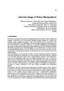
Fig. 1. The design architecture
physical world. The RHILS architecture utilized in this research is briefly explained in Section 2. Section 3 reviews the LM methodology. In Section 4 the entire concurrent design process is applied to the CRS CataLyst-5 industrial manipulator. The design results and some concluding remarks are discussed in Section 5. II. RHILS ARCHITECTURE The robotic hardware-in-the-loop simulation platform, detailed in [15],[16], provides a modular and generic testbed for synthesis and analysis of serial-link robot manipulators. The designer can change kinematic, dynamic, and control parameters in order to enhance the performance of the system. The platform consists of two parallel workstations, namely Host and Target, and physical components of a robot manipulator, i.e. joint modules and controller unit. For each joint module a load emulator is employed to apply simulated dynamic loads during the realtime execution. The collection of load emulators, joint modules and control system is called Hardware Emulation block. The Host and Target workstations and Hardware Emulation block are depicted in Fig. 1. A. Host Workstation This block is the link between the platform and designer. All preferences and options of design are set in the Host
computer, where the main code that governs the design process is executed. The options consist of initial kinematic, dynamic and control parameters, the predefined trajectory of the end-effector, gravity conditions, payloads, and the simulation duration. This block communicates with the controller to load control parameters such as proportional, integral, derivative, feedback and feedforward gains, and sends the command signals to the trajectory planner. The Host workstation also transfers data via a TCP/IP connection in order to load kinematic and dynamic parameters and inverse dynamics model of a design candidate to the Target workstation, and gathers positions and torque saved on the Target workstation using MATLAB® xPC Target® toolbox. B. Target Workstation This block is a barebones PC running the xPC Target® real time kernel. On this workstation a torque controller for load emulators and an inverse dynamics model of the manipulator, built in Simulink® and compiled through RealTime Workshop®, are executed. In the model torque signals are calculated based on the manipulator configuration and joints position, velocity and acceleration. Target workstation includes several interface cards in order to communicate with the joint modules and load emulators. Joint positions and torque simulated and sensed at the modules are easily displayed on a monitor attached to this PC using Simulink® scopes. In order to connect the Target workstation to the
569
hardware components a data acquisition board and a RS232 port are utilized. C. Hardware Emulation All physical hardware pieces that remain unchanged in the design process form Hardware Emulation block. In this research the first three joint modules of an industrial manipulator, called CRS CataLyst-5, their corresponding load emulators, and the CRS DM Master Controller unit are implemented. Each joint module consists of a stepper motor, an encoder mounted on the motor shaft, a harmonic drive as a transmission mechanism, and the driver unit. The module interfaces with both controller and Target workstation in order to receive control signals via motor driver and send joint positions back to the Target workstation. The load emulators are coupled directly to the joint modules in order to apply computed loads. The computed torque signals represent the arm’s dynamics and weight and payload effects that must be reflected on each joint actuator to have a genuine simulation of the real system. Since the applied torque should be followed accurately, a servo torque controller is designed and calibrated for each load emulator module. A reaction torque sensor is installed between the load emulator case (stator) and its mounting fixture to measure the feedback signal. The load emulator module sends and receives torque signals to and from the Target PC. The controller unit consists of a trajectory planner and a typical feedback/feedforward controller for each physical joint module. III. LM METHODOLOGY An alternative design methodology, called Linguistic Mechatronics (LM), for concurrent synthesis of multidisciplinary systems is developed in [14]. The methodology can be divided into three main phases. In the primary phase a set of proper intervals for design variables is selected, based on which initial configuration is determined for the proceeding optimization. However, in this research since a real robot is redesigned and the process can be safely started from the existing configuration, this step is skipped. The secondary phase specifies the design variables in order to maximize an index called overall design satisfaction. This phase involves single-objective optimization over a large number of design variables. The overall satisfaction is an aggregation of satisfactions corresponding to all design attributes. These satisfactions are defined based on design requirements and designer’s preferences. One of the unique features of LM methodology is dividing the design attributes into two subsets, labeled as must and wish attributes. Must attributes refer to costumer’s demands, i.e., the achievement of their associated design requirements are mandatory with no room for compromise. On the other hand, wish attributes refer to customer’s desires, i.e., their associated design requirements permit room for compromise and they should be achieved as much
(a) (b) Fig. 2. (a) CRS CataLyst-5 robot, (b) RHILS platform
as possible. These two inherently-different sets of attributes are aggregated separately to form the overall must and wish satisfactions. Since must attributes have to be satisfied simultaneously, a p-parameterized class of t-norm operators is employed to aggregate them. For aggregating wish attributes they are first divided into two cooperative sets of design attributes, based on the direction of their satisfaction gradient. The satisfactions corresponding to each subset of wish attributes are then combined by means of a qparameterized class of t-norm operators. Finally an αparameterized class of generalized mean operator merges the two satisfactions and introduces the overall wish satisfaction. Subsequently, by aggregating the overall must and wish satisfactions the overall design satisfaction is calculated by the same p-parameterized class of t-norms. The design satisfaction level depends on the designer’s attitude in aggregating the attribute satisfactions that is modeled by fuzzy aggregation parameters (p, q and α). However, different designers may not have a consensus on the notion of satisfaction. Therefore, in the final phase the system performance must be checked against a holistic supercriterion to capture the objective aspects of design considerations in terms of physical performance. Designer’s attitude is adjusted through iterations to achieve the enhanced system performance based on the supercriterion. IV. IMPLEMENTATION In this section the LM methodology is implemented for redesigning kinematic, dynamic and control parameters of the CRS CataLyst-5 manipulator. The RHIL platform is also utilized to evaluate the following design attributes. Fig. 2 shows the real CRS CataLyst-5 manipulator against the RHILS platform developed using the manipulator components. A. Design Variables CRS CataLyst-5 is a five degree-of-freedom industrial manipulator consisting of five rotary joints. The first three joint modules, called waist, shoulder and elbow, respectively, have a crucial role in the manipulator performance, and they are physically included in RHILS platform. The last two joints are for roll and pitch motions of the manipulator wrist, and they are modeled in computer. Kinematic characteristics of the manipulator are defined based on standard Denavit-Hartenberg convention. Therefore, length (li), offset (di) and twist (αi) are deemed as
570
kinematic design variables of the ith link. In order to take into account dynamic parameters of the robot, each link is considered as an L-shaped circular cylinder along link length and offset. The radius of such cylinder (ri), as a design variable, specifies dynamic parameters of the ith link knowing the material and thus link density. The CRS DM Master Controller unit generates control signals for each joint consisting of proportional (Pi) and integral (Ii) gains along with gains for feedback velocity ( Kv fb ,i ) and acceleration ( Ka fb ,i ) and also feedforward velocity ( Kv ff ,i ) and acceleration ( Ka ff ,i ). Since the last two joints are small at the tip of the manipulator with much less moments of inertia than that of the other joints, their control gains are not considered in the design. Consequently, the design problem deals with thirty-eight design variables in total to identify the most desirable kinematic, dynamic, and control configuration of the manipulator.
B. Design Attributes Based on Linguistic Mechatronics, design attributes are divided into must and wish attributes and design availabilities are considered as must attributes because of their similar nature. 1) Must design attributes The must design attributes include: Design availabilities: Each design variable has an acceptable range of values, considering its physical nature and manufacturing constraints. They are taken into account by the following inequality expression. Xk
≤ Xk ≤ Xk
min
max
(k=1,2,…,n.);
(1)
where X k is the kth design variable, n is the number of design variables and X k
min
and X k
max
are the minimum and
maximum values for X k , respectively. Joint constraint: Each joint module has restrictions due to physical properties of the actuator, mechanical configuration of the manipulator and its location in the working environment. Since real joint modules are used in the design process, physical characteristics of joints are considered automatically. However, the shape and location of links impose restrictions on the ranges of joint movements that j means limits on the ith joint angle at jth working point ( θ i ). Torque constraint: Each joint module can handle a max maximum amount of torque ( τ i ), usually corresponding to the stall torque of the ith joint motor. Therefore,
links in free space so that the end-effector reaches a target point. The farthest point that the manipulator can reach is the maximum reachability of the robot (R) and because of environmental constraints it should not exceed a certain number (Rmax). 2) Wish design attributes The must attributes are mostly the constraints that are imposed by environment or physical properties of the manipulator. However, the main mission of the robot is reflected in the wish attributes. In this paper the following wish design attributes are considered as design objectives. End-effector error: The typical ultimate task for a robot manipulator is to follow predefined trajectories. Therefore, the measured error at the working points is an appropriate wish attribute to minimize. If Δtj and δ tj are the maximum permitted errors for the end-effector position and orientation, respectively, at the jth working point of the tth trajectory, then the end-effector error can be defined as: 1 E= NT
T
2 2 2 ⎛ Δx 2 + Δy 2 + Δz 2 δxtj + δy tj + δz tj tj tj tj ⎜ + ⎜ Δtj δ tj j =1 ⎜ ⎝ (3) N
∑∑ t =1
⎞ ⎟ ⎟ ⎟ ⎠
where Δxtj , Δy tj and Δz tj are the position errors in x, y and
z directions, δxtj , δy tj and δz tj are the orientation errors about x, y and z directions at the jth working point of the tth trajectory, and T is the number of trajectories. Note that orientation errors are assumed sufficiently small so that the overall orientation error can be considered as a vector. Also, for the 5-degree-of-freedom CataLyst-5 manipulator only yaw and roll angles of the end-effector were considered. A maximum of 1 mm for the translational error and 6º for the orientation error are assigned for this design. Manipulability: The manipulability index is used for checking the manipulator singularity at the working points. This measure can be expressed as [17]: M =
1 N
N
∑ cond ( J
0 j
);
(4)
j =1
0
where cond ( J j ) is the condition number of Jacobian
is the ith joint maximum absolute value of the
matrix with respect to the base frame at jth working point. At the singular points the manipulability index approaches infinity and its minimum value is one. Therefore, this wish attribute is satisfied when manipulability index is close enough to one. Structural length index: A desirable manipulator is the one with a larger workspace using the least amount of material. Structural length index summarizes this tradeoff in a simple formulation as:
torque between jth and (j-1)th working points. Maximum reachability: The reachability of a robot manipulator is defined as its ability to move its joints and
⎛ ndof ⎞ QL = ⎜ ∑ (li + d i ) ⎟ / 3 V ; (5) ⎝ i=1 ⎠ where ndof is the number of joints and V is the workspace
j
max
τi ≤τi
where
max
max
τi
j
(i=1,2,…,ndof. j=1,2,…,N.);
(2)
571
TABLE I DESIGN VARIABLES AND ATTRIBUTES RANGES
volume that can be numerically calculated based on a method detailed in [18]. This ratio roughly encapsulates the relative amount of structure required to generate a given workspace. Thus, a good design would be a manipulator with a small QL. Total required torque: The torque generated by the joint motor is proportional to the electric current, and subsequently the energy consumed at the joint. Therefore, the total required torque at jth working point, expressed in (6), can be considered as a wish attribute to minimize.
a i (m ) d i (m )
α i (o ) θ i (o) max
τ i (N.m)
R (m ) E M QL
ndof
τT = ∑ τi ; j
ri (m)
j
τ T ( N .m)
(6)
All Control Gains
i =1
where τ i is the torque of joint i at jth working point. Once the design attributes are specified, their satisfactions are defined based on designer’s preferences. Table I specifies the range of design variables and attributes. In Fig. 3 trapezoidal fuzzy membership functions are employed in order to demonstrate attribute satisfactions for redesigning CRS CataLyst-5 manipulator. Subsequently, for each design candidate the satisfactions are aggregated to determine the overall design satisfaction. A function called fminsearch in optimization toolbox of MATLAB® is used to maximize the level of satisfaction in design. This phase generates a set of optimally satisfactory solutions for design while altering designer’s attitude parameters (p, q and α). Finally, designer’s attitude should be adjusted based on a holistic supercriterion. The total energy consumption of the manipulator calculated by (7) is employed to define an appropriate performance supercriterion. j
ndof θ i
N
Energy ( X S ;p, q, α ) = ∑ ∫ τ i dθ i ;
(7)
i =1 θ 1 i
where XS is the set of design variables corresponding to a satisfactory design candidate. Ultimately, by minimizing this criterion over optimally satisfactory solutions set (CS), the best design (X*) is achieved.
Energy( X * ) = min( Energy( X S ;p, q, α )) ; X S ∈C S
(8)
V. RESULTS AND CONCLUSION The final results of the manipulator re-design are shown in Table II. The initial values of design variables were based on the current configuration of CRS CataLyst-5. The final design solution shows notable modifications in some of the design variables. With respect to the manipulator dynamics, i.e., link radii, the third link has been decreased by almost 10%. Furthermore, the length of link 3 has also changed by 0.7%. These modifications result in 17.5% reduction of the link mass. Therefore, in terms of dynamic and kinematic design, the third link has been modified considerably. In addition, all control gains have slightly modified by an average of 0.8% in order to enhance the design attributes.
i= 1 i= 2 i= 3 i= 4 i= 5 [0,0.2] [0,0.2] [0,0.2] [0,0.2] [0,0.2] [0,0.5] [0,0.5] [0,0.5] [0,0.5] [0,0.5] [0,0.5] [0,0.5] [0,0.5] [0,0.5] [0,0.5] [-180,180] [-180,180] [-180,180] [-180,180] [-180,180] [-180,180] [-110,0] [-90.6,35] [-110,110] [-180,180] [0,13.8] [0,13.8] [0,13.8] [0,4.8] [0,2.4] [0,0.87] [0,2] [1,24] [0,1.6] [0,12.5] [-∞,+∞]
li, ,
Fig. 3. Satisfactions on design variables and attributes
From Table II a considerable improvement is made in the end-effector error, E. The final error is approximately 78 times less than its initial value. An increase in the level of satisfaction for all other wish attributes can be observed from Table II, as well. Therefore, based on the designer’s preferences, all the considered attributes have been enhanced. All such design candidates were checked against an objective supercriterion, which is the total consumed energy, through altering attitude parameters. Ultimately, the configuration with the minimum energy consumption was picked as the final design. The energy consumption was improved by 10%. Adjustment of attitude parameters during the design process indicates that the initial designer’s attitude in aggregating must satisfactions was appropriate. That is, the value of p did not change through the attitude adjustment. However, in aggregating wish satisfactions the designer was originally too conservative, and the values of q and α were decreased and increased, respectively, through the attitude adjustment. This implies that instead of focusing on the worst wish attribute, the designer should equally stress all wish design attributes in order to improve the energy consumption of the system. The RHILS platform discussed in this paper provided a real-time and concurrent design platform for robot
572
TABLE II DESIGN RESULTS li (mm )
ri (mm )
Initial Final
i= 1 65.6 65.7
i= 2 27.7 28.0
Initial Final
i= 1 254.0 255.0
i= 2 0.0 0.0
i= 3 24.1 21.8
i= 4 10.0 10.0
i= 5 10.0 10.0
i= 1 0.0 0.0
i= 2 254.0 253.6
i= 4 0.0 0.0
i= 5 0.0 0.0
i= 4 0.0 0.0
i= 5 0.0 0.0
i= 1 -90.0 -90.8
i= 2 0.0 0.0
i= 3 0.0 0.0 Kv fb ,i
i= 4 -90.0 -90.7
i= 5 0.0 0.0
i=1 40.7 41.0
i=2 40.0 40.3 Ka ff ,i
i=3 20.0 20.2
i=1 3473.0 3483.6
i=2 100.0 100.8
i=3 120.0 120.9
j= 4 0.838 1.000
j= 5 0.609 0.896
d i (mm )
i= 3 0.0 0.0
α i (o )
Pi
Ii
Initial Final
i=1 18.32 18.46
i=2 20.00 20.16
Initial Final
i=1 43.41 43.76
i=2 100.00 100.80
μE
μM
0.000 1.000
0.606 0.620
i=3 12.00 12.10
i=1 0.07325 0.07381
i=2 0.05000 0.05039 Kv ff ,i
i=3 80.00 80.62
i=1 i=2 i=3 59.010 40.000 30.000 59.471 40.311 30.230 Wish Satisfactions
Ka fb ,i
Initial Final
Initial Final
E
M
1.4787 0.0189
20.7223 19.4923
μQ
L
0.455 0.626 QL
1.3091 1.3025
j= 1 0.838 1.000
[3] [4] [5]
[6] [7]
μτ
j= 1 9.3557 8.3071
j= 2 10.2754 9.1391
[8]
[9] [10] [11]
[12]
A. Castano, A. Behar, and P. M. Will, “The Conro modules for reconfigurable robots,” IEEE/ASME Transactions on Mechatronics, Vol. 7, No. 4, pp. 403-409, 2002. J. Hewit, “Mechatronics design – the key to performance enhancement,” Robotics and Autonomous Systems, No. 19, pp. 135142, 1996. J. Leitner, “Space Technology Transition Using Hardware in the Loop Simulation,” Proceedings of the 1996 Aerospace Applications Conference, Vol. 2 , pp. 303-311, February 1996. H. Hanselman, “Hardware-in-the-loop Simulation Testing and its Integration into a CACSD Toolset,” IEEE International Symposium on Computer-Aided Control System Design, September 1996. M. Linjama, T. Virvalo, J. Gustafsson, J. Lintula, V. Aaltonen, and M. Kivikoski, “Hardware-in-the-loop Environment for Servo System Controller Design, Tuning, and Testing,” Microprocessors and Microsystems, Vol. 24, No. 1, pp. 13-21, 2000. G. Stoeppler, T. Menzel, and S. Douglas, “Hardware-in-the-loop Simulation of Machine Tools and Manufacturing Systems,” Computing and Control Engineering Journal, Vol. 16, No. 1, 2005. B. L. Ballard, R. E. Elwell Jr., R. C. Gettier, F. P. Horan, A. F. Krummenoehl, and D. B. Schepleng, “Simulation Approaches for Supporting Tactical System Development,” John Hopkins APL Technical Digest (Applied Physics Laboratory), Vol. 23, No. 2-3, pp.
[13] [14] [15] [16]
[17] [18]
573
[p,q,α ]
j
j= 3 9.3561 8.3071
j
(N .m ) j= 4 9.3561 8.3071
[10,1.5,0.5] [10,0.7,1.2] Energy (J )
T
τT
REFERENCES
[2]
i=3 0.10000 0.10077
j= 2 j= 3 0.593 0.838 0.896 1.000 Wish Design Attributes
manipulators. Implementing physical components reduced the simulation complexity, yet included the phenomena that are difficult to model. Using analytical model of the parts that need to be designed in concurrence with the hardware components has made the platform suitable for rapid design alterations. In addition, Linguistic Mechatronics as an alternative approach for synthesis of multidisciplinary systems was employed. This methodology not only simplified the optimization complexities of concurrent design, but also brought in, in a formal way, the subjective notions of design.
[1]
i= 3 254.0 255.9
j= 6 0.609 1.000
j= 5 10.2172 9.1394
6.2549 5.6307 Overall Satisfaction μ 0.250 0.607
j= 6 10.2172 8.3071
311-324, 2002 J. C. Piedboeuf, J. de Carufel, F. Aghili, and E. Dupuis, “Task Verification Facility for the Canadian Special Purpose Dexterous Manipulator,” Proceedings of the 1999 IEEE International Conference on Robotics and Automation, USA, 1999. X. Hu, “Applying Robot-in-the-loop Simulation to Mobile Robot Systems,” 12th International Conference on Advanced Robotics, Seattle, USA, pp. 1-8, July 2005. X. Cyril, G. Jaar, and J. St-Pierre, “Advanced Space Robotics Simulation for Training and Operations,” AIAA Modeling and Simulation Technologies Conference, Denver, USA, August 2000. H. Temeltas, M. Gokasan, S. Bogosyan, and A. Kilic, “Hardware in the Loop Simulation of Robot Manipulators through Internet in Mechatronics Education,” The 28th Conference of the IEEE Industrial Electronics Society, Sevilla, Spain, Vol. 4, November 2002. A. Martin and M. R. Emami, “Design and Simulation of Robot Manipulators using a Modular Hardware-in-the-loop Platform,” in M. Ceccarelli (ed.) Robot Manipulators: Programming, Design, and Control, I-Tech Education and Publishing, Vienna, Austria, 2008. Z. M. Bi, W. A. Gruver and S. Y. T. Lang “Analysis and Synthesis of Reconfigurable Robotic Systems,” Concurrent Engineering: Research and Applications, Vol. 12, No. 2, June 2004. R. Chhabra and M. R. Emami, “Linguistic Mechatronics,” IEEE/ASME International Conference on Advanced Intelligent Mechatronics, Xian, China, July 2-5, 2008. A. Martin and M. R. Emami, “An Architecture for Robotic HardwareIn-the-loop Simulation,” Proceeding of the 2006 IEEE International Conference on Mechatronics and Automation, HeNan, China, 2006. A. Martin, E. Scott and M. R. Emami, “Design and Development of Robotic Hardware-In-the-loop Simulation,” 9th International Conference on Control, Automation, Robotics and Vision, Singapore, December 5-8, 2006. Z. M. Bi, Y. F. Li and W, J, Zhang, “A New Method For Dimensional Synthesis of Robotic Manipulators,” 5th National Applied Mechanisms and Robotics Conference, Cincinnati, 1997. M. Ceccarelli, G. Carbone and E. Ottaviano, “An Optimization Problem Approach for Designing Both Serial And Parallel Manipulators,” The International Symposium on Multibody Systems and Mechatronics Proceedings of MUSME, Brazil, March 6-9, 2005.