8th Conference on Systems Engineering Research March 17-19, 2010, Hoboken, NJ Paper #1569270867
Concurrent Systems Engineering in Aerospace: From Excel-based to Model Driven Design Holger Schumann1, Heinrich Wendel2, Andy Braukhane3, Axel Berres1, Andreas Gerndt1, Andreas Schreiber2
German Aerospace Center e.V. (DLR), Germany Software Quality Assurance and Embedded Systems, Simulation and Software Technology, Braunschweig Email:
[email protected],
[email protected],
[email protected] 2 Distributed Systems and Component Software, Simulation and Software Technology, Cologne Email:
[email protected],
[email protected] 3 Institute for Space Systems, Bremen Email:
[email protected]
1
Abstract Concurrent engineering is a modern and very effective discipline of systems engineering. In the European space domain, the European Space Agency is the pioneer in this area and has performed early design studies for 10 years now. The Integrated Design Model (IDM) is still the state of the art in concurrent engineering software environments. It is based on Microsoft Excel, which induces several benefits and drawbacks related to concurrent engineering. The German Aerospace Center has used the IDM for several design studies and has identified two promising approaches to further increase the effectiveness of the concurrent engineering software environment by using modern model driven software technologies. Both concepts were implemented, and in this paper they are compared to each other and opposed to the IDM.
Introduction Concurrent Engineering (CE) is a modern and effective discipline of systems engineering. Due to the increasing complexity of technical systems, it becomes more and more challenging to specify optimal system configurations. During concurrent design sessions, the customer and an interdisciplinary team of engineers study some recommendable configurations of the intended system mainly in personal discussions. This helps to overcome problems in understanding the needs and requirements of a different engineering discipline, and to find a comprehensive solution. The Concurrent Engineering Facility (CEF) (Schumann et al. 2008) of the German Aerospace Center (DLR) was built to enable concurrent engineering for space systems, providing a very modern
audio, video, and computer equipment. Besides the CE process and the team, which are both provided by the DLR Institute of Space Systems, the software environment is a central key element of concurrent engineering (Bandecchi et al. 2000). The DLR institute Simulation and Software Technology has built the CEF in Bremen and develops a new and modern software environment supporting concurrent engineering of space systems. Nowadays, it is still state of the art to use Microsoft Excel for early design phases of technical systems. The European Space Agency (ESA) has used its Excel based Integrated Design Model (IDM) for many years to make feasibility studies of space missions following the concurrent engineering approach (Domizio 2008). Further examples for Excel based space design tools are: • SMAD (Wertz 1999) support software tool by KB Sciences Inc. • SCALES for nano- and microsatellites, TU Delft (Aas et al. 2009) • Concurrent Design Platform (CDP) by J-CDS (InPro 2009) DLR currently uses the IDM and has gained experiences by using this tool in several design studies. During the performed studies, DLR has identified several main requirements for a concurrent engineering software environment and has disclosed some IDM related limitations. Furthermore, the IDM is not designed to support later design phases, which resulted in the development of new approaches for CE software without losing the advantages of Excel. This paper presents the DLR requirements for a CE software environment identified by the studies performed at DLR and discusses the advantages and drawbacks of Excel based design in general and in detail on the example of ESA’s Integrated Design Model (IDM).
After that, two promising approaches implemented by the DLR institute Simulation and Software Technology are presented and discussed. Those approaches integrate the power of Excel with a modern integration platform, the Remote Computing Environment (RCE) (Seider et al. 2009), that has also been developed at DLR. RCE introduces modern technologies from the software engineering world, OSGi (OSGi 2009) and Eclipse (McAffer 2005), into the domain of systems engineering. The paper closes with a review of the new approaches in contrast to the pure Excel based ones.
Requirements on Concurrent Engineering Software Environments Within the last years, DLR has identified the following general requirements for a complete concurrent engineering (CE) software environment. Because supporting collaboration is a key aspect of CE software, requirements regarding collaboration were further refined thereafter. General Requirements. Supporting Study management means, the software shall provide at least the definition of a new study with its name, its main objectives, its customer’s contact information, and its data stores. The access to old studies with all of their results should be available as well. • Team management comprises functionality to define the team with names, working place, contact information, and representatives. Furthermore, roles required by the study, e.g. that of a system engineer or of the person responsible for a specific subsystem, are defined and assigned to the team members. • Requirements management allows to add, to list, and to modify requirements for the system which is being developed. Besides common information (name, id, status …), each requirement entry should contain fields for description, rationale, relations (to other requirements or to the implementing component), history of changes, and discussions. Moreover, new upcoming problems and open questions should be managed in one of the central lists. Every entry should be assignable to a team member or role in order to derive a list of tasks for everyone. • A scheduling module shall provide the possibility to arrange meetings in order to find proper dates, times, and meeting rooms, as well as to invite the corresponding team members. Additionally, type, objectives, and agenda of the meeting must be manageable. The module shall further display lists of finished and planned meetings and shall provide links to related data stores. As a result, the access to meeting results and resulting tasks becomes easier.
• The documentation and data management has to organize all incoming and resulting documents, starting from kick-off presentations up to lessons learned documents, as well as all produced data, e.g. CAD models. A clear overview of documents and data shall be provided and all other software modules shall refer to this module for offering an easy access to the documents. This central management of all documents and data also helps to avoid inconsistencies. Collaboration related Requirements. Collaboration support is a very central part of a CE software environment and especially aims at team based working in CE sessions as well as post processing phases. The implementations presented in this paper focus on this aspect. The Excel based tools named above also concentrate on this point. Only the CDP by J-CDS addresses some of the mentioned requirements. Besides improving the personal communication via email and instant messaging clients, the collaboration support has to meet the following functional requirements related to information and data exchange: • Distributed work: The software must provide mechanisms to synchronize the local work (local data) with the work of all other team members on the current user’s demand. The data store must avoid data inconsistencies and shall be accessible all the time from every work station. The software must allow working online as well as offline (connected to the data store or not connected). • Authentication and Authorization: The software must provide a mechanism to authenticate the user. Only team members of the current study are allowed to access the study’s data store. Furthermore, the software must assure that a specific role is assigned to the current user in order to exclusively grant access rights for specific parts of the data store or system (e.g. disciplines or subsystems). • Component breakdown: The software must provide a functionality to hierarchically split the entire system, e.g. into top level elements, subsystems, and units. It must offer the possibility to use predefined components with predefined parameters and calculations (see below). Additionally, it must be possible to define optional components and to link trade-off information to them. Parameters must uniquely be assignable to individual components. • Parameter management: Parameters like mass or power consumptions for operation and standby describe a single component and finally the entire system. The goal of system design is to specify the parameters and its values as accurate as possible during several iterations. The software must provide a possibility to create new parameters and to modify existing ones. Besides common data like description
and unit, the parameter information should contain constraints and notes for its value. The software must enable the user to share his parameters with other team members as well as allow other users to request for parameters. Additionally, the software must provide a clear overview of all parameters with different discipline specific views or suitable filters. • Calculation management: The software must provide a mechanism to create new formulas for calculations and modify existing ones. As arguments in the formulas both must be allowed, passing own parameters as well as shared parameters from other team members. The calculated result shall lead to a new parameter. • Central data: The software must provide a functionality to store central data like physical constants, units, and operation modes. The calculations and resulting parameter values have to depend on the defined modes. • Version control: The software must provide a mechanism to create different versions of the stored data. This helps to get a common view of the current data status for all team members and forms the precondition for managing iterations. Furthermore, the software must allow to rollback to a previous status in order to correct committed errors. Version control also enables traceability by logging any data change, and it must provide a history graph for selected parameter values to enable the evaluation of the iteration success. • Import/Export: The software should provide means of exchanging data with complementary engineering software by an export and import feature. The constellation of the team highly depends on the different study objectives, so that the team composition changes quite often. This leads to the following non functional requirements: • Intuitive use: The software must be intuitive, i.e. a new team member must be able to use the software within less than 1 hour of introduction. • Documentation: An appropriate software documentation must be provided, which is easily accessible by one click or key press within the system.
The Integrated Design Model (IDM) The Integrated Design Model (IDM) was developed under the sponsorship and initiative of ESA’s General Studies Program (GSP) to support the concurrent engineering approach. It is based on Microsoft Excel but extends Excel’s functionality by the use of macros to remove or to weaken the drawbacks concerning concurrent engineering mentioned above. It has been in operational use for 10 years now and has supported designing systems in over 100 ESA studies. The IDM is both, a hierarchical model for space systems and a distributed
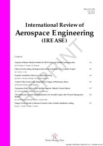
implementation of the model in Excel. (Bandecchi et al. 2000) Hierarchical Model. One instance of the model is created for each study, as displayed in figure 1. A study can consist of different Elements, e.g. a transport vehicle and a lander. Each element is associated with general Element Information and is made up of different Subsytem, e.g. the attitude and orbit control subsystem or the telecommunication subsystem. Subsystems are split into Units. The telecommunication subsystem, for example, contains a transmitter and a receiver unit. Finally, each unit is described by different Parameters, e.g. their power consumption or weight and sizes.
Figure 1. Hierarchical view of the Integrated Design Model (IDM) Excel Implementation. In practice, this model is not realized as coherent database model, but split into different Excel workbooks in order to allow concurrent editing of the whole system by a team of engineers. Each workbook either represents one subsystem or a special discipline like calculation of overall costs, or a mixture of both, like power management. Within a workbook the appropriate parts of the system are modeled as parameter lists. Each workbook consists of four types of worksheets: • Output: The output sheet contains a list of parameters this workbook calculates and provides to all other workbooks. A parameter consists of a name, a value and a unit. The name is linked to the hierarchical structure; pwr_E2_unit3_Top_max, for example, refers to the maximal temperature (a power management value) of the third unit in the second element of the study.
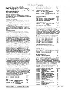
• Input: The input sheet contains a list of parameters that are required by the workbook in order to calculate the values for the output sheet. • Calculation: Calculation sheets do not need to follow a special structure and are editable by the engineers. They contain formulas for actually calculating the values, which are based on the parameters from the input sheet, linking them to the output sheet. • Presentation: Presentation sheets serve the purpose of displaying the calculated information in a visually appealing manner to all team members. The exchange of parameters from output to input sheets is handled by Excel macros via a central DataExchange workbook, as shown in figure 2. After the session leader triggers the macro, all output parameters will be copied into this central workbook, allowing each engineer to update his local input values afterwards. This procedure can only work if all workbooks are located on a central network share.
Figure 2. Structural Concept of the Integrated Design Model (IDM)
Evaluation of Excel based Approaches All Excel based tools benefit from general advantages of Excel. Concerning CE, Excel also induces some general limitations. The following sections describe the benefits and drawbacks from Excel in general and discuss some IDM related aspects. Benefits. Custom tables: Excel is well designed to create user defined lists and tables. In combination with comprehensive filters, the tables greatly help to get a clear overview of all data and present it to others. This can be used to handle lists of objectives, team members, tasks, meetings, and so on. Especially, a big amount of parameters can be managed with one Excel sheet,
which partly satisfies the requirements related to parameter management. • Custom calculations: Excel provides an easyto-learn language for efficiently expressing simple formulas and calculations. The calculation inputs can be obtained from other cells, worksheets or even completely different files. This enables the user to split complex calculations into several less complex parts and makes calculations more maintainable. Because it is rather easy to reproduce the data flow, calculations are quite transparent to other users, increasing the acceptance of Excel in engineering domains. This meets the requirements concerning central data and calculation management completely. • Import/Export: The very strong import and export wizards made Excel the leading data exchange tool supplying widely used data formats like the comma separated values format (CSV) or the extensible markup language (XML). This entirely meets the requirement concerning import/export. • Known usage: Excel is widely used and well known worldwide. It is safe to assume that all team members know how to use Excel, so there is no need of an additional educational effort. If still needed, an online help system is integrated. All in all, this meets the requirements regarding intuitive use and documentation completely. • Extendable: The integrated macro and scripting functionality via Visual Basic for Applications (VBA) allows to easily extend Excel’s functionality. Drawbacks. Not distributed: Excel does not provide support for reliable distributed working. Data or cell contents can be shared with other team members via cell references, but neither the data consistency nor the existence of the referenced file can be guaranteed. A simultaneous writing into one Excel file is not possible, even though different cells would be affected. • Unwanted changes: Excel is optimized to provide quick access to all cell contents, but this can also lead to unwanted changes of cell contents. Furthermore, changing the structure of tables by copying or inserting a row, for example, could easily destroy cell references and formula bindings. • Missing tree views: Although the table based view of Excel is quite powerful, it can not compete with a tree like representation. In consequence, subrequirements, sub-components, or deeper nesting can not be displayed in a suitable manner. Besides the unhandy grouping and outlining functionality, this prevents the creation of an arbitrary deep component tree. • Long formulas: A minor drawback for the calculation management requirement is that the calculation formulas are displayed in one single row.
For long formulas it would be nicer to have a tiny text editor to present the formula in a better, more readable way. • No version control: With every saving, old data is overwritten and irretrievable deleted. Besides the unhandy track changes function, there is no chance for traceability or to get and restart from older data versions apart from periodically copying the corresponding Excel file by hand. • System dependency: Excel is designed to run on the Windows operating system only and has a rather high dependency on this, especially if macros are used. Because of many relevant system settings and security configurations, it is even not trivial to exchange Excel files by using macros between different windows systems.
supporting feasibility or very early design studies and still has some issues. Nowadays, there are very promising software technologies to provide optimal conditions for satisfying all of the postulated requirements above. The base for software related to systems engineering is an appropriate data model for representing the data in both a human and a machine readable manner. The data model of the IDM has already been presented; additionally research from the TU Munich is described below. After validating the requirements described in chapter 2 against those existing models, an enhanced one is presented. Based on that model, two concepts for integrating the Excel based approaches with a modern software platform are introduced.
IDM related aspects. The IDM version 6.14 was successfully used for several early design studies at DLR. It provides very useful predefined sheets and has greatly advanced the good study results. Nevertheless, some limitations were identified: • The flexibility of the IDM is limited. On the one hand, the IDM has to be adapted to user’s organization specific or study specific aspects. This affects the needed subsystems or workbooks or any special output-input connections between different subsystems for example. On the other hand, it is difficult to change the responsibility of an element or unit or to add a new parameter during the session. Additionally, there are only up to 10 operation modes available for use. • The usability of the IDM could be improved. Copying and pasting similar IDM units puts the defined formula bindings at risk and the big amount of unused cells and parameters weaken the clear overview sometimes. The fact that the count of defined units must be inserted explicitly by hand and that the top elements have to be inserted into every workbook manually, are error-prone procedures. • To allow the data exchange between the IDM workbooks, the workbook files have to be stored on a central Windows file server. This increases the configuration effort, especially when firewalls are involved. An additional limitation is that the complete workbook, including all its units and parameters, can only be modified by one user at the same time, limiting concurrency.
The Data Model. There has been a lot of research in model-based design of satellite systems in addition to the already presented parametric approach used by the IDM. Based on a general model for arbitrary systems developed by (Walther 1994), (Wilke 2002), who is specialized in the area of satellite development, and (Schiffner 2007) transferred this model to objectoriented concepts. According to Walter’s general model, a system consists of a number of Elements, each associated with a list of parameters, divided into Input, Output and Properties. Functions calculate output values based on inputs and properties. Outputs map to inputs via Relations. Those models still do not meet all described requirements, lacking the following features: • Static and dynamic Model: The model must be static as well as dynamic in relation to the system behavior. The calculation of system parameters and their optimization during Phase 0/A is static. The system parameters are calculated before a simulation. To perform a simulation of the system behavior a dynamic model is necessary. This model is able to cover the requirements of the later phases. • Abstract classes: The concept of abstract classes has to be integrated. This allows a logical model of system, e.g. a solar panel, which does not exactly specify its dimensions or the power it produces, being able to fill in this information during the design process. • Hierarchical and discipline specific views: It must be possible to switch between a hierarchical and discipline specific views. Having a hierarchical view, as in the models of TU Munich, is very helpful to provide an overview about the whole system. But in general, each engineer is responsible for a specific discipline, representing the approach of the IDM, and needs a specific view. For example, all components related to power management and consumption have to be shown to the power engineer.
New Approaches Due to the increasing complexity of systems and the raising acceptance of concurrent engineering (CE), the demand for using CE in more than early design phases grows continuously. The IDM is designed for
• More base types: Besides Project, Variant and Element as base types, there must be more possibilities to structure the parts, e.g. Study, Subsystem and Unit. • Versioning: All data must be versionable. This allows reverting to previously (better) states or comparing different design possibilities. • Mapping to IDM: A mapping to the IDM has to be doable, allowing a smooth transition and compatibility of the spreadsheet based approach and the new data model.
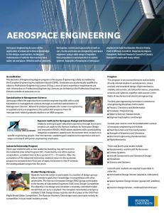
Figure 3. Data model based on approaches of the TU Munich Based on those requirements and the previously mentioned models, a new data model has been created, as displayed in figure 3. Abstract classes are supported by combining class and instance into the entity Element. Abstract classes are defined implicitly by containing Parameters without values. Setting discipline specific filters for tables are possible by assigning a discipline to each Parameter. The Element type was generalized by adding a Type attribute, allowing to specify arbitrary types like Study or Subsystem. Additionally, a Version attribute was introduced. The mapping will be explained in the first concept, the dynamic aspects of the model in the second. The Remote Computing Environment (RCE). The Remote Computing Environment (RCE) is an integration platform developed by the Institute for Simulation and Software Technology of the German Aerospace Center and Fraunhofer Institute for Algorithms and Scientific Computing. Based on Java and the widely used (OSGi 2009) component standard, it delivers all features a modern integration platform has
to provide, like privilege- and data management, transparent remote access, and a workflow system. The Eclipse RCP platform (McAffer 2005) is used in order to integrate graphical components, another popular defacto standard. One of the core features of RCE is the distributed data management. It can manage both file like data and structured data, the latter one persisted as XML files. Each RCE instance offers its own data management, working in the background, automatically saving and versioning the contents of all files a user is working on in the Project Explorer GUI component. Data is referenced to by a Data Reference consisting of a UUID and the unique identifier of the RCE instance. Remote data transfer is handled by the communication bundle, allowing transparent access to remote RCE instances via pluggable protocols; currently supported are RMI and SOAP. Each Data Reference can additionally be associated with permissions to individual users or roles. (Seider et al. 2009) The Remote Computing Environment was developed in a BMBF sponsored project called Sesis. Although not related to aerospace but shipbuilding, the requirements are quite similar. Shipbuilders, suppliers, and shipyards have to work closely together in a distributed manner on the design of a ship, needing a common and extensible platform in order to construct models and run simulations. This helps to reduce the costs during the initial design phase, which accounts for ca. 85% of the overall costs. (Schroedter 2008)
Figure 4. Deployment of RCE in the CDF in Bremen RCE is used as integration platform, meaning all clients will use RCE as primary user interface, exchanging data with the data management of a central RCE server instance, as shown in figure 4. This is a base requirement in order to overcome the mentioned disadvantages of excel macros and a central network share. RCE as base platform provides modern data
management features like versioning, remote access, and modelling of data structures, additionally allowing arbitrary communication mechanisms between the individual instances. Based on this deployment, the clients will in the first step reuse the existing excel sheets integrated into RCE, but the data will automatically be transferred into the new data model. In the second step, additional tools independent from Excel are introduced, lightening the work with this model and providing new features. Concept 1: Integration. In order to provide a smooth transition and bigger acceptance of the user base, existing studies must be automatically converted into the new data model. The basis of transferring the IDM into the new data model is given by the names of the individual parameters. As already described in the section about the IDM, they already contain the required hierarchical information. All parameters of the output sheet will be split at each underscore, one element created for each but the last part (if not existent yet) and one output for the last part, filled with the given value. Although this does not fill the whole data model, it will create a complete hierarchical view of the system. Functions and properties cannot be automatically mapped, since they are part of the calculation sheets which do not follow a given structure. The same applies for inputs, because it cannot be uniquely identified which output needs which inputs to be calculated. In consequence, relations which depend on inputs cannot be mapped as well.
Figure 5. Part of the structure of an orbiter study Figure 5 shows the mapping of the power subsystem of the VirSat study to the new data model. Each box represents one element with its output parameters, the lines reflect the composition structure.
Altogether, the integration approach takes over all the benefits of Excel and solves the issues concerning distributed work and version control. However, the user interface related problems and the IDM related aspects can not be eliminated by this approach. Concept 2: Replacement. In order to remove the user interface related drawbacks of Excel, the work on completely replacing the IDM was integrated into the Virtual Satellite project. Based on the presented data model and functionalities of RCE, an application called VirSat was developed to support the design of space systems within several development phases. Several aspects for safeguarding the benefits of Excel have been considered. In general, the VirSat software development is based on modern model driven architecture (MDA) approaches which allow very short implementation cycles and a fast response to any feature request of the user. In detail, there are already multiple views of tables and multiple built-in computations offered, but additional table views or computations can be easily added by the software developer within a few hours. To ease the usage of VirSat, a description is displayed on the screen for every component, every list, and every list item like parameter or mode. Additionally, the parameters already known from the IDM were copied into related components within the component library. The comfortable usability is provided by the professional underlying Eclipse framework mainly. The extended functionalities are described as follows: To meet the distributed work requirement, the internal data representation of VirSat can be locally saved as XML files. These local files can be committed to a central repository, which is managed by a professional version control server. Other team members can now update their local data with the centrally stored data on demand. Thereby, the integrated version control client merges the remote changes into the local ones. The server and the network can be configured to allow access every time from everywhere, and the implementation allows online as well as offline working. The version control server (Subversion) creates a new data revision with every upload or commit of data automatically, partly meeting the version control requirement. Currently, the user interface does not provide the ability to select an individual parameter and display the history of its value, though the data would be already available in the system. Every instance of VirSat is configurable for specific roles, representing the responsibility for a discipline or subsystem. This assures that the current user can only modify the components he is responsible for. Unwanted changes in wrongly opened workbooks are not possible anymore, and additionally, this avoids
conflicts while merging remote data into local data using the built in version control client.
constraints and notes in the user interface, modifying a stack of parameters and creating filters have been implemented. Calculations can also be added or modified in the detailed data sheet of a component. Up to now, only predefined calculations can be selected and no custom ones can be defined. If a parameter being a function parameter of a calculation is modified, the parameter carrying the calculation result is updated immediately. Central data can be defined by providing a corresponding component like the asteroids mentioned above. For every top element, the system engineer can define any modes, which are immediately copied to all subcomponents. The responsible engineer can now assign several of his parameters to each mode which makes the parameter value mode dependent. Mode dependent parameters change their value corresponding to the currently selected operation mode. VirSat is prepared to export the component hierarchy to the computer aided design tool CATIA (Dassault Systems) and to export the parameters to other third party applications.
Fig. 6. Component tree view of the system to study A tree view was integrated into VirSat to represent the hierarchical component breakdown of the entire system. As can be seen in figure 6, several top level elements like mothership, lander and space environment were defined in this example. The lander is the only system worked on in the current study and therefore contains concrete subsystems. In opposite to the others, the power subtree is displayed with a black font, showing that the current user holds the role for being responsible for the power system only and is not able to modify any other component. This discipline specific view accentuates the power subsystem while preserving read access for all other components. The two possible asteroids, which can be targeted by the lander, are located in the space environment and described by useful parameters being accessible by all team members. Components and subcomponents can be appended to the subsystems by the responsible team members. The user can either create completely new components or he can drag predefined components from a component library into the depicted tree view. A double click on a component opens its detailed data sheet, displaying parameter tables and file references. In the detailed data sheet of a component, parameters can be easily added or modified. Equivalent to the IDM, the parameter value can be inserted, calculated, or a given value can be temporarily overwritten. To completely meet the parameter management requirement, the functionality for requesting parameters from other subsystems, setting
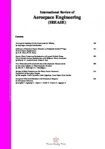
Figure 7. Screenshot of the application ’Virtual Satellite’ Figure 7 shows a screenshot of the implemented application. On the left side, two tree views are shown, representing the hierarchical component breakdown of the current system and a component library with predefined components. On the upper right, the detailed data sheet of the power subsystem is partly displayed, and on the lower right, the current mass budget of the lander element is presented as it is known from the IDM. First applications of VirSat showed that this approach is best prepared to take over the benefits from the IDM, to weaken its drawbacks and to smoothly transfer knowledge and data to further phases in the development cycle of complex technical systems.
However, the engineers missed the feature for defining custom computations in addition to the built-in ones, and they criticized limitations while creating custom views for reporting and presenting. Because these features provided by Excel are taken over by the integration approach, it was concluded that the combination of both approaches satisfies all of the mentioned requirements for a software environment considerably increasing the effectiveness of concurrent engineering.
Conclusions In this paper, the DLR requirements on a software environment for supporting the concurrent engineering method in early development phases were presented. In the space domain, Excel based design tools like ESA’s Integrated Design Model (IDM) are widely used. The benefits and drawbacks of Excel based design were discussed and contrasted with the identified requirements. It was concluded that Excel as well as the IDM is not designed to meet all of the identified requirements. As main problems with Excel, the following were identified: • Excel does not provide reliable support for distributed work, centrally stored data can be modified by all users, and there is no built-in support for data versioning. • The user is easily able to change the structure or content of (not protected) tables, which could obstruct or falsify formula bindings behind. • Excel can not dynamically change a specific cell content dependent on table structures (e.g. count of rows) and vice versa - in the IDM, the correct count of used units have to be inserted manually, though it could be derived from the count of unit rows, and furthermore, the count of possible modes is limited to 10. • Excel is highly dependent on the operating system, which could cause a big configuration overhead, especially if different workstations are involved. Two promising approaches have been implemented by the DLR institute Simulation and Software Technology to improve the Excel based design approach. In the first implementation, the Excel based data model of the IDM was replaced by a managed data model and the Excel calculation engine as well as its user interface was integrated into a modern distributed software framework RCE, based on Eclipse. In the second implementation, Excel was replaced by the Eclipse based framework completely. Even though both implementations are best prepared to meet all requirements, both implementations still have some drawbacks.
Though the integration approach solves the problems related to distributed work entirely, this approach takes over the difficulties related to the Excel user interface and operating system dependency. The approach concerning complete replacement fixes a big amount of the user interface related problems and solves the operating system dependency. But it still lacks providing calculation sheets for the definition of custom computations. It was concluded that the combination of both implementations clears the way to a modern software environment for concurrent engineering of any technical systems. Further research is done in enhancing the second approach to compete with the power of Excel formulas in order to replace it completely.
References Aas, C.L.O. and Zandbergen, B.T.C. and Hamann, R.J. and Gill, E.K.A., “Development of a System Level Tool for Conceptual Design of Small Satellites.” 7th Annual Conference on Systems Engineering Research, April, 2009 Bandecchi, M. and Melton, B. and Gardini, B. and Ongaro, F., “The ESA/ESTEC Concurrent Design Facility.” Proceedings of 2nd European Systems Engineering Conference (EuSEC 2000), Munich, September, 2000 Di Domizio, D. and Gaudenzi, P., “A Model for Preliminary Design Procedures of Satellite Systems.” Concurrent Engineering, 16(2), 149– 159., 2008 InPro Report, Tech. report, EU integrated project 026716-2 within 6th Framework Programme, May, 2009 McAffer, Jeff and Lemieux, Jean-Michel, “Eclipse Rich Client Platform: Designing, Coding, and Packaging Java Applications.” Addison Wesley Longman, 2005 OSGi Alliance, OSGi Service Platform, Core Specification, Release 4, Version 4.2. Schiffner, Michael Markus, “Eine objektorientierte Modellierungsmethode fuer die simultane Systementwicklung.” Ph.D. thesis, TU Muenchen, 2007 Schroedter, Sandra and Gosch, Thomas, “SESIS - Ship Design and Simulation System.” Computer Applications and Information Technology in the Maritime Industries, COMPIT, 2008 Schumann, Holger et al., “Overview of the new Concurrent Engineering Facility at DLR.” 3rd International Workshop on System Concurrent Engineering for Space Applications (SECESA), October, 2008
Seider, Doreen and Wend, Joachim and Schreiber, Andreas “Embedding Existing Heterogeneous Monitoring Techniques into a Lightweight, Distributed Integration Platform.”, D-Grid Monitoring Workshop, 2009 Walther, Christian “Systemtechniches Verfahren zur Bestimmung der Zusammenhaenge zwischen Eigenschaften und Funktionsstruktur technischer Systeme.” Ph.D. thesis, TU Muenchen, 1994 Wertz, J.R. and Larson, W.J. “Space Mission Analysis and Design.”, 3rd edn. Microcosm Press Springer, 1999 Wilke, Martin, “Integrierter modellbasierter Satellitenentwurf.“ Ph.D. thesis, TU Muenchen, 2002
Biography Holger Schumann holds a degree in computer science and has been working at the German Aerospace Centre (DLR) for 8 years now. He has gained experiences for software verification and validation in several projects. Furthermore, he manages the building of the Concurrent Engineering Facility at DLR as well as the development of the software environment “Virtual Satellite”.