International Review of Electrical Engineering (I.R.E.E.), Vol. 10, N. 6 ISSN 1827- 6660 November – December 2015
Condition Monitoring of Induction Motors Based on Stator Currents Demodulation Elhoussin Elbouchikhi1, Vincent Choqueuse2, Mohamed Benbouzid2, 3 Abstract – Over the past several decades, induction machine condition monitoring have received increasing attention from researchers and engineers. Several induction machine faults detection techniques have been proposed that are based on vibration, temperature, and currents/power monitoring, etc. Motor current signature analysis is a cost-effective method, which has been widely investigated. Specifically, it has been demonstrated that mechanical and electrical induction machine faults can be effectively diagnosed using stator currents demodulation. Therefore, this paper proposes to investigate the use of demodulation techniques for bearing faults detection and diagnosis based on stator currents analysis. If stator currents are assumed to be mono-component signals, the demodulation techniques include the synchronous demodulator, the Hilbert transform, the Teager energy operator, the Concordia transform, the maximum likelihood approach and the principal component analysis. For a multi-component signal, further preprocessing techniques are required such as the Empirical Mode Decomposition(EMD) or the Ensemble EMD (EEMD).The studied demodulation techniques are demonstrated for bearing faults diagnosis using simulation data, issued from a coupled electromagnetic circuits approachbased simulation tool, and experiments on a 0.75kW induction machine test bed. Copyright © 2015 Praise Worthy Prize S.r.l. - All rights reserved.
Keywords: Induction Machine, Bearing Faults, Diagnosis, Stator Currents Analysis, Demodulation Techniques
Consequently, it is mandatory to implement a condition-based maintenance. It consists of three main steps: data acquisition, data processing, and decisionmaking. Most of the methods for induction machine monitoring could be classified into several categories: vibration monitoring, torque monitoring, temperature monitoring, oil/debris analysis, acoustic emission monitoring, optical fiber monitoring, and current/power monitoring [1]-[6]. MCSA has several advantages since it is a non-invasive technique that avoids the use of extra sensors [6]-[9]. Moreover, the stator currents are usually measured for other purposes such as control and protection. Hence, most of the recent research topics on induction machine faults detection have been directed toward electrical monitoring with special emphasis on stator current processing [10]-[13]. Several studies have been focused on induction machine faults effect over the stator currents. In fact, in [14]-[15], the authors have presented an analytical approach to model the impact of the mechanical and bearing faults. This approach is based on traditional MMF and permeance wave approach for the airgap magnetic flux density computation [16]. This study has demonstrated that a healthy induction machine already contains a great number of spectral components due to its supply voltage, rotor slotting and possible iron saturation. Moreover, any mechanical faults may lead to
Nomenclature MCSA MMF PCA IA IF EMD EEMD IMF HHT SD HT FT FFT DESA TEO CT MLE CMC
Motor Current Signature Analysis Magneto Motive Force Principal Component Analysis Instantaneous Amplitude Instantaneous Frequency Empirical Mode Decomposition Ensemble EMD Intrinsic Mode Function Hilbert-Huang Transform Synchronous Demodulator Hilbert Transform Fourier Transform Fast Fourier Transform Discrete Energy Separation Algorithm Teager Energy Operator Concordia Transform Maximum Likelihood Estimation Coupled Magnetic Circuits
I.
Introduction
Induction machine is widely used in industrial applications thanks to its reliability, ruggedness and low cost. Unfortunately, several faults can occur, which may lead to process failure and damage to humans and surrounding equipment.
Copyright © 2015 Praise Worthy Prize S.r.l. - All rights reserved
704
E. Elbouchikhi, V. Choqueuse, M. E. H. Benbouzid
eccentricity and load oscillation faults. The eccentricity fault causes amplitude modulation and load oscillation leads to frequency modulation of the stator currents. The modulation frequency depends on the operating conditions of the machine and the fault severity. Besides, the stator currents can be frequency and/or amplitude modulated and this modulation is correlated with the defected components of the bearing [17]. Generally speaking, the current is sinusoidally frequency and/or amplitude modulated when a fault occurs. Based on this signal modeling approach, it seems that the most adapted tools to extract a fault indicator are demodulation techniques. Hence, current demodulation has been investigated for faults detection and diagnosis. Typical examples include broken rotor bars [18]-[22], gearbox faults [23] and bearing faults [7], [14], [17], [24]. In order to perform currents demodulation, several authors have employed classical demodulation techniques such as the synchronous demodulator [22], [25], [26], the Hilbert transform [18]-[20], [22], [27], time-frequency distributions [14], [17], [28]-[30] or adaptive tracking of sine waves [31]. Joint IA-IF estimation based on the Concordia transform is investigated in [7], [21], [32]. One advantage of this transform relies on its low computational cost; however, its domain of validity is restricted to balanced three-phase systems. In [7], a technique based on PCA is presented for joint IA-IF estimation. Moreover, the Teager-Kaiser energy operator has been investigated in [33] for faults detection in induction machine with broken rotor bars, mixed eccentricity, and single-point bearing faults based on stator currents. For multi-component and non-stationary stator currents, a filtering stage is required if the modes are separable [34].Otherwise, techniques such as EMD and EEMD are required in order to extract monocomponent signals (called IMFs) from the stator currents [35], [36]. The HHT is then used in order to compute the time-frequency representation of the IMFs [37]. Finally, fault detection criteria are computed in order to reveal the IMFs impacted by the fault and measure the fault severity. In this paper, demodulation techniques are presented and demonstrated for bearing faults detection in induction machine. Indeed, these approaches are compared for instantaneous amplitude and phase computation, and fault severity tracking [38]. The advantages and drawbacks of each technique are highlighted on simulated and experimental data. The contribution of this paper is threefold. First, we present a widely used demodulation techniques for fault detection. Then, we provide a performance comparison based on simulation and experimental data. Finally, we propose a fault detection criterion that allows measuring the fault severity. The remainder of the paper is organized as follows. Section II presents demodulation techniques used for stator currents processing and section III focuses on the performance of these techniques on simulated data for bearing faults detection through stator current analysis.
Finally, section IV provides some experimental results for bearing faults detection and section V concludes this paper.
II.
Demodulation Techniques
Mono-component signal is a sinusoid possibly modulated in amplitude and/or frequency, whereas a multicomponent signal is a one, which is composed of a sum of amplitude and/or frequency modulated sinusoids. Let us consider a (noisy) mono-component signal defined as: 𝑥[𝑛] = 𝑎[𝑛] cos(𝜙[𝑛]) + 𝑏[𝑛]
(1)
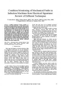
where 𝑎[𝑛] > 0 and 𝜙[𝑛] correspond to the instantaneous amplitude and phase, respectively. The component 𝑏[𝑛] corresponds to the noise component. From a statistical viewpoint, the goal of a demodulation technique is to estimate 𝑎[𝑛] and 𝜙[𝑛] from 𝑥[𝑛]. In order to achieve this goal, most of the demodulation techniques rely on the scheme presented in Fig. 1. First, the direct and quadrature components, which are given by 𝑦 [𝑛] = 𝑎[𝑛] 𝑐𝑜𝑠(𝜙[𝑛]) and 𝑦 [𝑛] = 𝑎[𝑛] 𝑠𝑖𝑛(𝜙[𝑛]), are estimated from 𝑥[𝑛]. Then, the analytic signal, 𝑧[𝑛], is constructed from the direct and quadrature components using the following formula 𝑧[𝑛] = 𝑦 [𝑛] + 𝑗𝑦 [𝑛] = 𝑎[𝑛]𝑒 [ ] ,where 𝑗 is the imaginary unit. Finally, the instantaneous amplitude and phase is estimated from the analytic signal as: 𝑎[𝑛] = |𝑧[𝑛]| 𝜙[𝑛] = 𝑎𝑟𝑔{𝑧[𝑛]}
(2)
where |. |and 𝑎𝑟𝑔{. }correspond to the modulus and argument, respectively. Finally the instantaneous frequency, which is defined as the derivative of the instantaneous phase divided by 2𝜋, can be estimated using a backward finite difference as: 𝑓[𝑛] =
𝐹 (𝜙[𝑛] − 𝜙[𝑛 − 1]) 2𝜋
(3)
where 𝐹 corresponds to the sampling rate. Within this general methodology, it should be mentioned that the most challenging step relies on the estimation of the direct and quadrature components. This section reviews the most common techniques for estimating these two components. II.1.
Mono-Dimensional Techniques
This section presents the most common demodulation techniques designed for mono-dimensional signals. These techniques assume that only one phase stator current 𝑥[𝑛] is available to estimate the direct and quadrature components.
Copyright © 2015 Praise Worthy Prize S.r.l. - All rights reserved
International Review of Electrical Engineering, Vol. 10, N. 6
705
E. Elbouchikhi, V. Choqueuse, M. E. H. Benbouzid
instantaneous amplitude and frequency directly from the incoming signal, 𝑥[𝑛] [43]. This algorithm is based on the discrete Teager energy operator (TEO), which is given by [44]: Ψ(𝑥[𝑛]) = 𝑥 [𝑛] − 𝑥[𝑛 + 1]𝑥[𝑛 − 1]
(6)
It is shown in [43] that the instantaneous amplitude and frequency can be estimated by:
Fig. 1. Analytical signal estimation
II.1.1. Synchronous Demodulator 𝑎[𝑛] ≈
Let us consider that the instantaneous phase is given by: 𝜙[𝑛] = 2𝜋𝑓 𝑛⁄𝐹 + 𝜑[𝑛], where 𝑓 corresponds to the carrier frequency and 𝜑[𝑛] is an unknown modulating signal. The SD estimates the 𝑎[𝑛] and 𝜑[𝑛] (not 𝜙[𝑛] directly) assuming that the carrier frequency is known. Fig. 2 illustrates the SD. First, the incoming signal, 𝑥[𝑛], is multiplied by the reference signals 𝑐𝑜𝑠(2𝜋𝑓 𝑛⁄𝐹 ) and 𝑠𝑖𝑛(2𝜋𝑓 𝑛⁄𝐹 ). After the multiplication stage, the output signal contains a baseband signal, which corresponds to the direct or quadrature component, and some high-frequency oscillations. In order to remove the high-frequency oscillations, a low-pass filter with a cut-off frequency close to 𝑓 is used. For grid connected induction machine, the carrier frequency is broadly equal to 50 or 60Hz.
Ψ(𝑥[𝑛]) 1− 1−
𝑓[𝑛] ≈
Ψ( [ ]
[
])
Ψ( [ ])
(7)
1 Ψ(𝑥[𝑛] − 𝑥[𝑛 − 1]) 𝑎𝑟𝑐𝑜𝑠 1 − 2𝜋 2 Ψ(𝑥[𝑛])
The discrete energy separation algorithm exhibits interesting property since it is less computationally demanding and has better time resolution than other demodulation techniques. The main drawback of this operator is its high-sensitivity to noise or to model mismatch. Moreover, it assumes that the estimated IF does not vary too fast or too greatly compared to the carrier frequency [44].
II.1.2. Hilbert Transform The Hilbert transform is a commonly used technique in signal processing for estimating the direct and quadrature signals. The estimation of the direct and quadrature components is illustrated in Fig. 3. The quadrature component is obtained using HT. For discrete signals, the HT is given by [40, Section 12.4]: 𝑦 =
ℎ[𝑛 − 𝑚]𝑥[𝑛]
(4) Fig. 2. Synchronous demodulator [39]
where the impulse response ℎ[𝑛] is equal to: ℎ[𝑛] =
2 𝑠𝑖𝑛 𝜋 𝑛 0,
,𝑛 ≠ 0
(5)
𝑛=0
It should be mentioned that the estimation of the quadrature component is not always possible. Specifically, the Bedrosian theorem has shown that this component can be estimated if and only if the spectra of the 𝑎[𝑛] and 𝑐𝑜𝑠(𝜙[𝑛]) are disjoint [41] (see Fig. 4). The Hilbert transform can also be computed for a real valued 𝑁-point discrete time signal efficiently using the FFT algorithm [42].
Fig. 3. Hilbert-based demodulation [39]
II.1.3. Energy Separation Algorithm Compared to the previous techniques, the discrete energy separation algorithm (DESA) estimates the
Fig. 4. Illustration of the Bedrosian theorem conditions
Copyright © 2015 Praise Worthy Prize S.r.l. - All rights reserved
International Review of Electrical Engineering, Vol. 10, N. 6
706
E. Elbouchikhi, V. Choqueuse, M. E. H. Benbouzid
II.2.
Multi-Dimensional Techniques
More precisely, this technique has the property to be optimal in the sense that it attains the Cramer-Rao bounds under some conditions [46]. Recently, the (deterministic) maximum likelihood has been derived for the estimation of the direct and quadrature components for three-phase systems with amplitude unbalance only (𝑑 = 1 and 𝜓 = 0) [47]. For systems with amplitude unbalance, the maximum likelihood technique leads to the following matrix:
Multi-dimensional demodulation techniques exploit the three-phase structure of the stator current signals. Under general conditions, the three-phase currents can be modeled as: 𝑥 [𝑛] = 𝑑 𝑎[𝑛] 𝑐𝑜𝑠(𝜙[𝑛] − 2𝑘𝜋⁄3 + 𝜓 ) + 𝑏 [𝑛] (8) where 𝑑 and 𝜓 corresponds to amplitude and phase unbalance, respectively, and 𝑘 = 0, 1, 2. Within the general framework, Fig. 5 describes a multi-dimensional demodulation technique. The estimation of the direct and quadrature component is obtained from a linear transform of the three phase signals. Mathematically, this linear transform can be expressed under a matrix form as follows: 𝑥 [𝑛] 𝑦 [𝑛] = 𝑯 𝑥 [𝑛] 𝑦 [𝑛] 𝑥 [𝑛]
𝑯 =
𝑯 =
√6 1 √2
−𝑑 𝑑
√3
√2
𝑑
−𝑑 𝑑 +2
−𝑑 √3
𝑑
+2
(11)
+ 𝑑
+ 𝑑 𝑑
In practice, it should be noted that the unbalance parameters 𝑑 are unknown and must be replaced by their estimates. In [47], it has been shown that the estimate of the unbalance parameters 𝑑 can be simply obtained from the eigen vector associated with the smallest eigen value of the samples covariance matrix 𝑹, which is defined as: 𝑟 𝑟 𝑟 𝑟 𝑟 𝑟 𝑹= (12) 𝑟 𝑟 𝑟
(9)
The Concordia transform (CT) is a linear transform that extracts two orthogonal components from the threephase stator currents. The matrix 𝑯 for Concordia transform is defined as: −1⎤ √6 ⎥ −1⎥ ⎥ √2 ⎦
𝑑
ℳ=𝑑
II.2.1. Concordia Transform Approach
−1
+ 𝑑 −𝑑
where:
where 𝑯 is a 2 × 3 matrix. The choice of the matrix 𝑯depends on the balance assumption. In the following, we present several structures for 𝑯.
⎡√2 2 ⎢√3 3⎢ ⎢0 ⎣
𝑑 1 𝑑 ℳ
where:
𝑟 =
1 𝑁
𝑥 [𝑛]𝑥 [𝑛]
(13)
II.2.3. Principal Component Analysis Approach
(10)
Principal component analysis (PCA) is a statistical tool that transforms a number of signals into a small number of uncorrelated components called the principal components. The PCA is based on the eigenvalues decomposition of the sample covariance matrix, 𝑹 (see (12)). Specifically, two principal components are obtained by setting:
For balanced systems (𝑑 = 𝑑 = 𝑑 = 1 and 𝜓 = 0), the CT leads to the least-square estimator of the direct and quadrature components [7], [32], [45]. The main drawback of CT relies on the balance assumption since systems are rarely balanced in abnormal operating conditions.
𝑯 = 𝛽𝚲
𝐒
(14)
where 𝚲 is diagonal matrix containing the two largest eigenvalues of 𝑹, 𝐒 is a semi-unitary matrix containing the associated eigenvectors, (. ) corresponds to the matrix transpose, and: Fig. 5. Multi-dimensional demodulation
𝛽=
𝑟 +𝑟 +𝑟 3
(15)
II.2.2. Maximum Likelihood Approach Under the assumptions that 𝜙[𝑛] is uniformly distributed in [0; 2𝜋] and that 𝑎[𝑛] and 𝜙[𝑛] are independent, the two principal components correspond to
The maximum likelihood estimation (MLE) is a powerful statistical technique for estimating unknown parameters. Copyright © 2015 Praise Worthy Prize S.r.l. - All rights reserved
International Review of Electrical Engineering, Vol. 10, N. 6
707
E. Elbouchikhi, V. Choqueuse, M. E. H. Benbouzid
the direct and quadrature components up to a constant phase indetermination [7]. Note that the constant phase indetermination is not an issue for the estimation of the instantaneous frequency since the latter is based on a phase difference (see (3)). In other words, the phase indetermination does not affect the estimation of the instantaneous amplitude and the instantaneous frequency. As opposed to other multidimensional techniques, the PCA-based technique is less restrictive since it holds whatever the balance assumption, which is an interesting property for fault detection in electrical machines. II.3.
2. 3. 4. 5.
III. Simulation Results This section reports on the performance of the demodulation techniques for induction machine bearing faults detection. The induction machine modeling approach is briefly presented. Then, the bearing fault is emulated in order to demonstrate the interest of the above-presented approaches.
Induction Machine Faults Detection based on Demodulation Techniques
The previously discussed demodulation techniques allow extracting the IA and IF from mono-component signals. Depending on the signal characteristics, Fig. 6 gives the demodulation technique to be applied for induction machines monitoring based on stator currents processing. Especially, in the case of multi-component signals, a filtering step is required in order to separate modes. In the case where the modes cannot be separated using filtering, more sophisticated techniques are required such as EMD and EEMD. After demodulation, the analytic signal and the corresponding IA and IF must be appropriately analyzed to assess the fault severity. Several papers have proposed to monitor the deviation of the analytic signal from a circle in the complex plane [53]-[54]. This approach holds when the stator current is amplitude modulated but is not appropriate when the stator current is frequency modulated since the fault only affects the rotational speed in the complex plane [7]. Hence, the variance of the IA, 𝑎[𝑛] and the IF, 𝑓[𝑛] are used as fault detection criteria. In fact, these criteria are related to the modulation indexes, which are proportional to the fault severity [7].The proposed criteria mathematical formulation is given by (16): 1 𝑁
(𝑎[𝑛] − 𝑚(𝑎[𝑛]))
1 𝐶 = 𝑁
(𝑓[𝑛] − 𝑚(𝑓[𝑛]))
𝐶 =
Fig. 6, Computation of the analytic signal, Estimation of the instantaneous amplitude, 𝑎[𝑛], and instantaneous frequency, 𝑓 [𝑛] using (2) and (3), Computation of the fault detection criteria; 𝐶 and 𝐶 in (16), Return𝑎[𝑛](𝑛 = 0, … , 𝑁 − 1), 𝑓 [𝑛](𝑛 = 0, … , 𝑁 − 1), 𝐶 and 𝐶 .
III.1. Induction Machine Modeling Under Faults Briefly An induction machine is considered as a highly symmetrical electromagnetic system. Any fault will therefore induce a certain degree of asymmetry [55]. The coupled magnetic circuits (CMC) approach combined with the arbitrary reference frames theory has been chosen for induction machines modeling [56]. The computation of the matrices containing all magnetizing, leakage, and mutual inductances is the key to a successful simulation of the squirrel cage induction machine. In the following, all the relevant inductances matrices are calculated using the winding function method [56]. The expression of the inductance matrix of the induction machine can be extracted from the flux or from the magnetic energy stored on the airgap. In order to emulate the induction machine faults, the harmonic contents of the stator current can be calculated satisfactory using a linear model of the machine [56], [58]. All the parameters are calculated from the actual geometry and winding layout of the machines rather than from transformed or equivalent variables. In this context, a Matlab-based tool of faulty induction machines has been developed to generate a fault database. It has been demonstrated in [15], [60] that single-point bearings faults induce mechanical eccentricities, but also load-torque variations. Hence, in the carried-out simulations, bearing faults are emulated by generating only one sort of physical phenomena: rotating eccentricities at bearing characteristic fault frequency 𝑓 .
(16)
where 𝑚(𝑋) denotes the mean of time series 𝑋. Algorithm 1 summarizes the proposed approach for fault detection in induction machine based on demodulation techniques. This algorithm will be used in the following for bearing faults detection in induction machines using simulated data and experimental signals.
III.2. Simulation Results In this section, a 4kW induction machine operating under nominal load condition has been simulated. Two machines have been considered: a healthy machine and a faulty one affected by mixed eccentricity. For these machines, the stator current signals have been recorded during 10seconds with a 1kHz-sampling rate.
Algorithm 1: Stator currents demodulation for faults detection in induction machine. Require: Signal samples 𝒙[𝑛]. 1. Estimation of the in-phase and quadrature components using appropriate demodulation technique as described in
Copyright © 2015 Praise Worthy Prize S.r.l. - All rights reserved
International Review of Electrical Engineering, Vol. 10, N. 6
708
E. Elbouchikhi, V. Choqueuse, M. E. H. Benbouzid
Fig. 6. Which demodulation technique to choose?
The simulation results for the estimation of the IA and IF using the demodulation techniques is given by Figs. 7 for mono-dimensional techniques and Figs. 8 for multidimensional approaches. The main conclusion that may be drawn from these figures is that the demodulation techniques allow to highlight the presence of the emulated fault. Moreover, this fault introduces both a sinusoidal frequency and amplitude modulation in the stator current. Several simulations have been performed in order to prove the interest of the demodulation techniques
for fault detection and severity measurement. Increasing the eccentricity degree increases the fault severity. Figs. 9 give the variation of the proposed fault detection criteria with respect to fault severity. It shows that the proposed fault detection algorithm allows measuring the fault severity. In fact, the fault detection criteria increase with respect to the fault severity. These simulation results demonstrate the interest of the proposed algorithm for faults detection in induction machines. These preliminary results are validated in the following using experimental data.
(a) Synchronous demodulator-based demodulation. (b) Hilbert transform-based demodulation. (c) Teager energy operator-based demodulation. Figs. 7. Stator current mono-dimensional demodulation for bearing fault detection
Copyright © 2015 Praise Worthy Prize S.r.l. - All rights reserved
International Review of Electrical Engineering, Vol. 10, N. 6
709
E. Elbouchikhi, V. Choqueuse, M. E. H. Benbouzid
(a) Concordia transform-based demodulation
(b) Maximum likelihood approach-based demodulation: d0 = 1, d1 = 1.0193, and d2 = 1.0162
(c) Principal component analysis-based demodulation
Figs. 8. Stator current multi-dimensional demodulation for bearing fault detection
by Figs. 10. The machine under test is a 230/400 V, 0.75kW, three-phase induction motor with 𝑝 = 1 and 2780rpm rated speed. The induction machine has two 6204.2 ZR type bearings (single row and deep groove ball bearings) with the following parameters: outside diameter is 47 mm, inside diameter is 20 mm, and pitch diameter D is 31.85mm. Bearings have 8 balls with an approximate diameter d of 12 mm and a contact angle of 0°. Figs. 11 give the bearing structure and the main dimensions. Bearing faults are obtained by simply drilling holes in different parts [61]. The measured quantities for off-line bearing fault detection were the line-currents. Data acquisition is performed by a 24 bits acquisition card with 10 kHz sampling frequency.
(a) Instantaneous frequency variance: C1
(b) Instantaneous amplitude variance: C2
(a) Schematic view of the test rig
Figs. 9. Fault detection criteria with respect to fault severity; S1: 5% eccentricity, S2: 10% eccentricity, S3: 15% eccentricity, S4: 20% eccentricity
IV.
Tacho Generator
Induction motor
Alternator
Experimental Results
The above signal processing methods are tested on experimental data recorded from an induction machine with bearing faults. IV.1. Experimental Setup Description This section illustrates the behavior of the proposed techniques for faults detection in induction machine experimental signals collected from a test rig illustrated
(b) Photos of the test rig mechanical part Figs. 10. Test rig.
Copyright © 2015 Praise Worthy Prize S.r.l. - All rights reserved
International Review of Electrical Engineering, Vol. 10, N. 6
710
E. Elbouchikhi, V. Choqueuse, M. E. H. Benbouzid
(a)
(b)
Figs. 11. Bearing structure with main dimensions (a) Stator current waveform
These stator currents have been acquired and stored for further processing using the proposed methods on Matlab. For all the experiments, the stator fundamental frequency was almost equal to 𝑓 = 50 𝐻𝑧. A healthy and a faulty single-phase stator current data collected from the experimental setup are shown in Figs. 12. Fig. 12(a) gives a single-phase stator current data waveform corresponding to a healthy and faulty state of the motor under 50% load condition. This figure shows that the stator currents are not exactly sinusoidal due to space harmonics. These space harmonics are visible on the stator current spectrum depicted in Fig. 12(b). Moreover, the stator current signal is a multi-component signal due to the presence of these supply frequency harmonics. In order to obtain an approximation of monocomponent signal, the current is band pass filtered with upper and lower cut-off frequencies equal to 80Hz and 20Hz and down-sampled to 200Hz. Then, the demodulation techniques are used to compute the analytical signal. Finally, the IA and IF are computed in order to reveal the presence of a bearing fault. IV.2.
(b) Corresponding spectrum Figs. 12. A healthy and faulty (Bearing cage fault) phase motor current data collected from the test rig
IV.2.2. Multi-Dimensional Techniques The multi-dimensional techniques performances are depicted in Figs. 14. As expected the stator current is frequency modulated when the bearing fault occurs. The CT based demodulation technique is easy to implement, but it is more appropriate for balanced systems. Indeed, the CT may lead to incorrect results for the unbalanced case. The MLE-based technique exhibits the property of being suited for unbalanced three-phase stator currents. It gives good results for amplitude unbalance since it gives the amplitude unbalance parameters estimates. However, MLE-based approach is not appropriate for phase unbalance. As opposed to CT, the PCA leads to a better IA and IF estimation whatever the balance assumption [7].
Bearing Faults Detection based on Demodulation Techniques
IV.2.1.
Mono-Dimensional Techniques
The IA and IF estimates based on mono-dimensional techniques are given by Figs. 13. From this figures, it can be deduced that the stator current is frequency modulated and the fault severity may be measured by computing the IF variance. Moreover, the mono-dimensional techniques perform well and exhibit the existence of the frequency modulation when a bearing fault exists. Regarding the SD, the modulation on the instantaneous amplitude can be explained by the low-pass filtering stage, which introduces oscillations. These oscillations are not responsible of the fault but are a result of the filtering stage. Even if the HT allows revealing the frequency modulation and subsequently the presence of the fault, it suffers from border effects (not visible on the figure because we give a zoom of the original figure). These border effects may lead to false conclusions on the health state of the bearing.
IV.3. Summary on Demodulation Techniques The IA and IF have been used in order to compute the fault detection criteria. Figs. 15 give the simulation results for several bearing faults severity. As expected, the IF variance increases as the fault severity increases. The IA does not change significantly, which means that the bearing fault introduces a frequency modulation, which can be highlighted by the variance of the instantaneous
Copyright © 2015 Praise Worthy Prize S.r.l. - All rights reserved
International Review of Electrical Engineering, Vol. 10, N. 6
711
E. Elbouchikhi, V. Choqueuse, M. E. H. Benbouzid
frequency. This result is in accordance with the theoretical study and the experimental validation in [15]. It must be emphasized that these techniques require a preprocessing step in order to obtain a mono-component signals. In fact, in the case where the signal cannot be assumed to be mono-component, more sophisticated techniques are required in order to extract the mono-component signals from the original one. The EMD and EEMD [52], [62][64] are the most used techniques for mono-component signals (IMFs) computation. The simulation results on experimental data are given in Figs. 16 where the HHT has been implemented using the G. Rilling’s subroutines for Matlab. These figures depict the 4 IMFs extracted
(a) Synchronous demodulator-based demodulation.
from the original signals and the corresponding Hilbert Huang transform [37]. The first IMF is the fundamental frequency and the other IMFs are present in the case of healthy and faulty machine. However, there energy is not the same for the healthy machine and the faulty one. The computation of the variance of the second, third, and forth IMFs shows an increase of the energy of these components due the presence of the failure. These results shows that the EMD can be used to compute one IMF from the original signal and the energy of the residue can be used as a fault indicator. Afterwards, a threshold based decision-making technique may allow distinguishing a faulty machine from a healthy one.
(b) Hilbert transform-based demodulation.
(c) Teager energy operator-based demodulation.
Figs. 13. Mono-dimensional techniques
(a) Concordia transform-based demodulation.
(b) Maximum likelihood approach-based demodulation: d0 = 1, d1 = 0.9849, and d2 = 1.0017
(c) Principal component analysis-based demodulation
Figs. 14. Multi-dimensional techniques
(a) Instantaneous amplitude variance: C1
(b) Instantaneous frequency variance: C2
Figs. 15. Failure severity measurement for bearing fault detection using the proposed approach
Copyright © 2015 Praise Worthy Prize S.r.l. - All rights reserved
International Review of Electrical Engineering, Vol. 10, N. 6
712
E. Elbouchikhi, V. Choqueuse, M. E. H. Benbouzid
(a) Healthy induction machine
(b) Faulty induction machine
Figs. 16. EMD performances on experimental data
V.
Conclusion
In this paper, we have investigated the use of demodulation techniques for bearing faults detection in induction machines. Several approaches have been presented for stator currents processing. It has been proven that the computation of the IF and IA variances allows deriving a reliable fault indicator. The performance of the proposed techniques has been evaluated on simulation signals issued from a coupled magnetic circuit’s model of a squirrel cage induction machine. Finally, the usefulness of the proposed techniques has been demonstrated on actual induction machine with bearing faults. The investigated techniques should however be investigated and validated for other induction machine faults such as broken rotor bars, torque oscillation, stator short-circuit, etc. In addition, further investigations are required in order to demonstrate the interest of the demodulation techniques for variable frequency power supply and adjustable speed drives.
[7]
[8]
[9]
[10] [11]
[12] [13]
References [1]
[2]
[3]
[4]
[5] [6]
[14]
O. Duque-Perez, L.-A. Garcia-Escudero, D. Morinigo-Sotelo, P.E. Gardel, and M. Perez-Alonso, “Analysis of fault signatures for the diagnosis of induction motors fed by voltage source inverters using ANOVA and additive models,” Electric Power Systems Research, vol. 121, pp. 1–13, April 2015. M. Drif and A. Cardoso, “Stator fault diagnostics in squirrel cage three phase induction motor drives using the instantaneous active and reactive power signature analyses,” IEEE Trans.Industrial Informatics, vol. 10, n°2, pp. 1348–1360, May 2014. X. Dai and Z. Gao, “From model, signal to knowledge: A datadriven perspective of fault detection and diagnosis,” IEEE Trans. Industrial Informatics, vol. 9, n°4, pp. 2226–2238, November 2013. A. Garcia-Perez, R. de Jesus Romero-Troncoso, E. Cabal-Yepez, and R. Osornio-Rios, “The application of high-resolution spectral analysis for identifying multiple combined faults in induction motors,” IEEE Trans. Industrial Electronics, vol. 58, n°5, pp. 2002–2010, May 2011. S. Nandi, H. A. Toliyat, and X. Li, “Condition monitoring and fault diagnosis of electrical motors - a review,” IEEE Trans. Energy Conversion, vol. 20, n°4, pp. 719–729, December 2005. M. Seera, C. P. Lim, D. Ishak, and H. Singh, “Fault detection and
[15]
[16] [17]
[18] [19] [20]
Copyright © 2015 Praise Worthy Prize S.r.l. - All rights reserved
diagnosis of induction motors using motor current signature analysis and a hybrid fmm-cart model,” IEEE Trans. Neural Networks and Learning Systems, vol. 23, n°1, pp. 97 108, January 2012. V. Choqueuse, M. E. H. Benbouzid, Y. Amirat, and S. Turri, “Diagnosis of three-phase electrical machines using multidimensional demodulation techniques,” IEEE Trans Industrial Electronics, vol. 59, n°4, pp. 2014–2023, April 2011. R. R. Obaid and T. G. Habetler, “Current-based algorithm for mechanical fault detection in induction motors with arbitrary load conditions,” in Proceedings of the 2003 IEEE IAS Annual Meeting, Salt Lake City, UT, Oct. 2003, pp. 1347–1351. M. E. H. Benbouzid and G. Kliman, “What stator current processing based technique to use for induction motor rotor faults diagnosis?” IEEE Trans. Energy Conversion, vol. 18, n°2, pp. 238–244, June 2003. N. Feki, G. Clerc, and P. Velex, “Gear and motor fault modeling anddetection based on motor current analysis,” Electric Power Systems Research, vol. 95, pp. 28–37, February 2013. A. Bellini, F. Filippetti, C. Tassoni, and G. A. Capolino, “Advances in diagnostic techniques for induction machines,” IEEE Trans. Industrial Electronics, vol. 55, n°12, pp. 4109–4126, December 2008. M. E. H. Benbouzid, “A review of induction motors signature analysis as a medium for faults detection,” IEEE Trans. Industrial Electronics,vol. 47, n°5, pp. 984–993, October 2000. E. Elbouchikhi, V. Choqueuse and M.E.H. Benbouzid, “Induction machine diagnosis using stator current advanced signal processing,” International Journal on Energy Conversion, vol. 3, n°3, pp. 76–87, May 2015. M. Blodt, J. Regnier, and J. Faucher, “Distinguishing load torque oscillations and eccentricity faults in induction motors using stator current Wigner distributions,” IEEE Trans. Industry Applications, vol. 45, no. 6, pp. 1991–2000, November/December 2009. M. Blodt, P. Granjon, B. Raison, and G. Rostaing, “Models for bearing damage detection in induction motors using stator monitoring,” IEEE Trans. Industrial Electronics, vol. 55, n°4, pp. 1813–1822, April 2008. B. Heller and V. Hamata, Harmonic Field Effects in Induction Machine (Elsevier Scientific Publishing Company, 1977). M. Blodt, D. Bonacci, J. Regnier, M. Chabert, and J. Faucher, “Online monitoring of mechanical faults in variable-speed induction motor drives using the Wigner distribution,” IEEE Trans. Industrial Electronics, vol. 55, n°2, pp. 522–533, February 2008. I. Jaksch, “Fault diagnosis of three-phase induction motors using envelopeanalysis,” in Proceedings of the 2003 IEEE SDEMPED, Atlanta (USA), August 2003, pp. 289–293. I. Jaksch and J. Bazant, “Demodulation methods for exact inductionmotor rotor fault diagnosis,” in Proceedings of the 2005 IEEE SDEMPED, Vienna (Austria), September 2005, pp.1–5. I. Jaksch and P. Fuchs, “Rotor cage faults detection in
International Review of Electrical Engineering, Vol. 10, N. 6
713
E. Elbouchikhi, V. Choqueuse, M. E. H. Benbouzid
[21]
[22]
[23]
[24]
[25] [26] [27]
[28]
[29]
[30]
[31]
[32]
[33]
[34]
[35]
[36]
inductionmotors by motor current demodulation analysis,” in Proceedings of the 2007 IEEE SDEMPED, Cracow (Poland), 2007, pp. 247–252. I. Jaksch and P. Fuchs, “Demodulation analysis for exact rotor faults detection underchanging parameters,” in Proceedings of the 2009 IEEE SDEMPED, Cargèse (France),August-September 2009, pp. 1–7. M. Pineda-Sanchez and M. Riera-Guasp, “Instantaneous frequency of the left sideband harmonic during the start-up transient: A new methodfor diagnosis of broken bars,” IEEE Trans. Industrial Electronics,vol. 56, n°11, pp. 4557–4570, November 2009. A. Mohanty and C. Kar, “Fault detection in a multistage gearbox by demodulation of motor current waveform,” IEEE Trans.Industrial Electronics, vol. 53, n°4, pp. 1285–1297, June 2006. M. Blodt, M. Chabert, J. Regnier, and J. Faucher, “Mechanical load fault detection in induction motors by stator current timefrequency analysis,”IEEE Trans. Industry Applications, vol. 42, n°6, pp. 1454–1463, November-December 2006. M. Begovic, P. Djuric, S. Dunlap, and A. Phadke, “Frequency tracking in power networks in the presence of harmonics,” IEEE Trans. Power Delivery, vol. 8, n°2, pp. 480–486, April 1993. M. Akke, “Frequency estimation by demodulation of two complex signals,” IEEE Trans. Energy Conversion, vol. 12, n°1, pp. 157–163, January 1997. R. Puche-Panadero, M. Pineda-Sanchez, M. Riera-Guasp, J. Roger-Folch, E. Hurtado-Perez, and J. Perez-Cruz, “Improved Resolution of the MCSA Method Via Hilbert Transform, Enabling the Diagnosis of Rotor Asymmetries at Very Low Slip,” IEEE Trans. EnergyConversion, vol. 24, n°1, pp. 52–59, March 2009. V. Climente-Alarcon, J. A. Antonino-Daviu, M. Riera-Guasp, R. Puche-Panadero, and L. Escobar, “Application of the Wigner– Ville distributionfor the detection of rotor asymmetries and eccentricity through highorderharmonics,” Electric Power Systems Research, vol. 91, pp. 28–36,October 2012. J. Antonino-Daviu, S. Aviyente, E. G. Strangas, and M. RieraGuasp, “Scale invariant feature extraction algorithm for the automatic diagnosis of rotor asymmetries in induction motors,”IEEE Trans. Industrial Informatics, vol. 9, n°1, pp. 100– 108, February 2013. E. Cabal-Yepez, A. G. Garcia-Ramirez, R. J. Romero-Troncoso, A. Garcia-Perez, and R. A. Osornio-Rios, “Reconfigurable monitoringsystem for time-frequency analysis on industrial equipment throughSTFT and DWT,” IEEE Trans. Industrial Informatics, vol. 9, n°2, pp. 760–771, May 2013. P. Dash and S. Hasan, “A fast recursive algorithm for the estimation of frequency, amplitude, and phase of noisy sinusoid,”IEEE Trans. Industrial Electronics, vol. 58, n°10, pp. 4847 –4856, October 2011. B. Trajin, M. Chabert, J. Regnier, and J. Faucher, “Hilbert versus Concordia transform for three phase machine stator current timefrequency monitoring,” Mechanical Systems &Signal Processing, vol. 23, n°8, pp. 2648–2657, November 2009. M. Pineda-Sanchez, R. Puche-Panadero, M. Riera-Guasp, J. Perez-Cruz, J. Roger-Folch, J. Pons-Llinares, V. ClimenteAlarcon, and J. A.Antonino-Daviu, “Application of the Teager Kaiser energy operator tothe fault diagnosis of induction motors,” IEEE Trans. Energy Conversion, vol. 28, n°4, pp. 1036– 1044, December 2013. M. Riera-Guasp, J. Antonino-Daviu, J. Rusek, and J. RogerFolch, “Diagnosis of rotor asymmetries in induction motors based on the transient extraction of fault components using filtering techniques,”Electric Power Systems Research, vol. 79, n°8, pp. 1181–1191, August 2009. J. Faiz, V. Ghorbanian, and B. M. Ebrahimi, “EMD-based analysis of industrial induction motors with broken rotor bars for identification of operating point at different supply modes,”IEEE Trans. Industrial Informatics, vol. 10, n°2, pp. 957–966, May 2014. Y. Amirat, V. Choqueuse, and M. Benbouzid, “EEMD-based wind turbine bearing failure detection using the generator stator currenthomopolar component,” Mechanical Systems & Signal
Processing,vol. 41, n°1, pp. 667–678, December 2013. [37] E. Elbouchikhi, V. Choqueuse, M. E. H. Benbouzid, J. F. Charpentier, and G. Barakat, “A comparative study of timefrequency representations for fault detection in wind turbine,” in Proceedings of the 2011 IEEE IECON, Melbourne (Australia), November 2011, pp. 3584–3589. [38] E. Elbouchikhi, V. Choqueuse, M. Benbouzid, and J. A. Antonino-Daviu, “Stator current demodulation for induction machine rotor faults diagnosis,” in Proceedings of the 2014 IEEEICGE, Sfax (Tunisia), March2014, pp. 176–181. [39] D. Vakman, “On the analytic signal, the Teager-Kaiser energy algorithm, and other methods for defining amplitude and frequency,” IEEE Trans. Signal Processing, vol. 44, n°4, pp. 791– 797, April 1996. [40] A. Oppenheim and R. Schafer, Discrete-Time Signal Processing(3rd ed.Prentice Hall, 2009). [41] B. Picinbono, “On instantaneous amplitude and phase of signals,” IEEE Trans. Signal Processing, vol. 45, n°3, pp. 552–560, March 1997. [42] L. MarpleJr, “Computing the discrete-time analytic? signal via FFT,”IEEE Trans. Signal Processing, vol. 47, no. 9, pp. 2600– 2603, September 1999. [43] P. Maragos, J. Kaiser, and T. Quartieri, “On amplitude and frequency demodulation using energy operators,” IEEE Trans. SignalProcessing, vol. 41, n°4, pp. 1532–1550, April 1993. [44] P. Maragos, J. Kaiser, and T. Quatieri, “Energy separation in signalmodulations with application to speech analysis,” IEEE Trans.Signal Processing, vol. 10, n°41, pp. 3024–3051, October 1993. [45] J. M. Aller, A. Bueno, and T. Paga, “Power system analysis using space vector transformation,” IEEE Trans. Power Systems, vol. 17, n°4, pp. 957–965, November 2002. [46] S. Kay, Fundamentals of Statistical Signal Processing: Estimation Theory (Prentice-Hall signal processing series, 1993, 17th Printing). [47] V. Choqueuse, A. Belouchrani, E. Elbouchikhi, and M. Benbouzid, “Estimationof amplitude, phase and unbalance parameters in three-phase systems: analytical solutions, efficient implementation and performanceanalysis,” IEEE Trans. Signal Processing, vol. 62, n°16, pp. 4064–4076, 15 August 2014. [48] J. Pons-Llinares, J. Roger-Folch, and M. Pineda-Sanchez, “Diagnosis of eccentricity based on the hilbert transform of the startup transient current,” in Proceedings of the 2009 SDEMPED, Cargèse (France), August-September2009, pp. 1–6. [49] H. Li, L. Fu, and Y. Zhang, “Bearing fault diagnosis based on Teagerenergy operator demodulation technique,” in Proceedings of the 2009 IEEE ICMTMA, Zhangjiajie (China), April 2009, pp. 594–597. [50] B. Xu, L. Sun, L. Xu, and G. Xu, “Improvement of the Hilbert method via ESPRIT for detecting rotor fault in induction motors at low slip,” IEEETrans. Energy Conversion, vol. 28, n°1, pp. 225–233, March 2013. [51] V. Pires, J. Martin, and A. Pires, “Eigenvector/eignevalue analysis ofa 3D current referential fault detection and diagnosis of an induction motor,” Energy Conversion & Management, vol. 51, n°5, pp. 901–907, May 2010. [52] J. Rosero, L. Romeral, J. Ortega, and E. Rosero, “Short-circuit detection by means of empirical mode decomposition and Wigner-Ville distribution for PMSM running under dynamic condition,” IEEE Trans. Industrial Electronics, vol. 56, n°11, pp. 4534–4547, November 2009. [53] S. Das, P. Purkait, and S. Chakravorti, “Space-vector characterization of induction motor operating conditions,” in Proceedings of the 2008 NPSC, Bombay (India), December 2008, pp. 512–517. [54] D. Diallo, M. Benbouzid, D. Hamad, and X. Pierre, “Fault detection and diagnosis in an induction machine drive: A pattern recognition approach based on concordia stator mean current vector,” IEEE Trans.Energy Conversion, vol. 20, n°3, pp. 512– 519, September 2005. [55] H. Toliyat, M. Arefeen, and A. Parlos, “A method for dynamic simulation of air-gap eccentricity in induction machines,” IEEE Trans. IndustryApplications, vol. 32, n°4, pp. 910–918, JulyAugust 1996.
Copyright © 2015 Praise Worthy Prize S.r.l. - All rights reserved
International Review of Electrical Engineering, Vol. 10, N. 6
714
E. Elbouchikhi, V. Choqueuse, M. E. H. Benbouzid
[56] E. Elbouchikhi, V. Choqueuse, and M. E. H. Benbouzid, “Current frequency spectral subtraction and its contribution to induction machines’ bearings condition monitoring,” IEEE Trans. Energy Co Conversion nversion nversion,, vol. 28, n°1, pp. 135 135–144, 144, March 2013. [57] G. Joksimovic, M. Durovic, J. Penman, and N. Arthur, “Dynamic simulation of dynamic eccentricity in indu induction ction machines-winding machines winding function approach,” IEEE Trans. Energy Conversion Conversion,, vol. 15, n°2, n 2, pp. 143 143–148, 148, June 2000. [58] G. Houdouin, G. Barakat, B. Dakyo, E. Destobbeleer, and C. Nichita,“A coupled magnetic circuit based global method for the simulationof squirrel cage induction machines under rotor and stator faults,” inProceedings of the 2002 ELECTRIMACS, ELECTRIMACS Montreal (Canada), August 2002, pp. 18 18–21. 21. [59] A. Knight and S. Bertani, ““Mechanical Mechanical fault detection in a medium sizedinduction motor using stator current monitoring,” medium-sizedinduction IEEE Trans. EnergyConversion, EnergyConversion, vol. 29, n° n°4, 4, pp. 753 753–760, 760, December 2005. [60] R. Schoen, T. Habetl Habetler, er, F. Kamran, and R. Bartheld, “Motor bearing damage detection using stator current monitoring,” IEEE Trans. IndustryApplications, IndustryApplications vol. 331 1,, nn°6, 6, pp. 1274– 1274–1279, 1279, November November-December December 1995. [61] Z. Obeid, S. Poignant, J. Regnier, and P. Maussion, “Stator currentbased indicators for bearing fault detection in ssynchronous ynchronous machine by statistical frequency selection,” in Proceedings of the 2011 IEEE IECON, IECON, Melbourne (Australia Australia), Australia), November 2011, pp. 2036 2036– –2041. 2041. [62] G. Rilling, P. Flandrin, and P. Gonalves, “On empiri empirical cal mode decompositionand its algorithms,” in Proceedings of the 2003 IEEE IEEE--EURASIP EURASIP Workshop on Nonlinear Signal and Image Processing Processing,, Grado (Italia), 2003. [63] Y. Yu, Y. Dejie, and C. Junsheng, “A roller bearing fault diagnosis method based on EMD energy entro entropy py and ANNS Journal of Sound andVibration ANNS,”Journal andVibration,, vol. 294, n°1-2, n°1 2, pp. 269– 269 277, June 2006. [64] D. Yu, J. Cheng, and Y. Yang, “Application of EMD method and Hilbertspectrum ilbertspectrum to the fault diagnosis of roller bearings,”Mechanical bearings,”Mech Mechanical Systems ems & SignalProcess SignalProcessing,, vol. 19, nn°2, 2, pp. 259 259–270, 270, March 2005.
Vincent Choqueuse was born in Brest, France, in 1981. He received the Dipl. Dipl.-Ing. Ing. and the M.Sc. degrees in 2004 and 2005, respectively, from the Troyes University of Technology, Troyes, France, and the PhD degree in 2008 from the University of Brest, Brest, France. Since September September 2009, he has been an Associate Professor with the Institut Universitaire de Technologie of Brest, University of Brest, Brest, France, and a member of the Institut de Recherche Dupuy de Lôme – IRDL (FRE CNRS 3744). Dr. Choqueuse research interests incl include ude signal processing and statistics for power systems monitoring, Smart Smart-Grid, Grid, digital communication and digital audio. He has also developed a free web application for online signal processing and analysis: www.sp4mass.com. Mohamed El Hachemi Benbouzid was born in Batna, Algeria, in 1968. He received the B.Sc. degree in electrical engineering from the University of Batna, Batna, Algeria, in 1990, the M.Sc. and Ph.D. degrees in electrical and computer engineering from the National Polytechnic Institute of Grenoble, Grenoble, France, in 1991 and 1994, respectively, and the Habilitation à Diriger des Recherches degree from the University of Picardie “Jules Verne,” Amiens, France, in 2000. After receiving the Ph.D. degree, he joined the Professional Institute of Amiens, University of Picardie “Jules Verne,” where he was an Associate Professor of electrical and computer engineering. Since September 2004, he has been with the Institut Universitaire de Technologie of Brest, University of Brest, Brest, France, wher wheree he is a Professor of electrical engineering. Prof. Benbouzid is also a Distinguished Professor at the Shanghai Maritime University, Shanghai, China. His main research interests and experience include analysis, design, and control of electric machines, va variable riable-speed speed drives for traction, propulsion, and renewable energy applications, and fault diagnosis of electric machines. Prof. Benbouzid is an IEEE Senior Member. He is the Editor Editor--in-Chief Chief of the International Journal on Energy Conversion (IRECON). He is also also an Associate Editor of the IEEE Transactions on Energy Conversion, the IEEE Transactions on Industrial Electronics, the IEEE Transactions on Sustainable Energy, and the IEEE Transactions on Vehicular Technology. He was an Associate Editor of the IEEE/A IEEE/ASME SME Transactions on Mechatronics from 2006 to 2009.
Authors’ information 1
ISEN Brest, FRE CNRS 3744 IRDL – Institut de Recherche Dupuy de Lôme,, 20, Rue Cuirassé Bretagne, 29200 Brest, France Lôme France. E-mail mail::
[email protected] elbouchikhi@isen bretagne.fr 2
University of Brest, FRE CNRS 3744 IRDL – Institut de Recherche Dupuy de Lôme Lôme,, Rue de Kergoat, CS 93837, 29238 Brest Cedex 03, France E-mail mailss:
[email protected] Vincent.Choqueuse@univ brest.fr Mohamed.Benbouzid@univ brest.fr
[email protected] 3
Shanghai Maritime University, 201306 Shanghai, China China.
Elhoussin Elbouchikhi was born in Khemisset, Morocco, in 1987. He received the diploma engineer degree (Dipl. (Dipl.-Ing.) Ing.) in Automatic and Electrical Engineering and Research Master’s degree in Automatic Systems, Computer Science and Decision, from the National Polytechnic Institute of Toulouse (ENSEEIHT), Toulouse, France, in 2010, and the Ph.D degree in 2013 from the University of Brest, Brest, France. He has been a Post PostDoctoral Researcher at ISEN Brest, Brest, France and an Associate Member of the LBMS_Lab (EA 4325) from October 22013 013 to September 2014. Since September 2014, he is an Associate Professor at ISEN Brest, Brest, France and is an affiliated member of the Institut de Recherche Dupuy de Lôme – IRDL (FRE FRE CNRS 3744 3744). His current research interests include electrical machines faults detection and diagnosis, and signal processing and statistics for power systems monitoring.
Copyright © 2015 Praise Worthy Prize S.r.l. - All rights reserved
International Review of Electrical Engineering, Vol. 10, N. 6
715