This manual applies to version 9.0 of BIG-IP® Local Traffic ManagerTM, BIG-IP®
Load ... F5 reserves the right to change specifications at any time without notice.
Configuration Guide for Local Traffic Management version 9.0
MAN-0122-01
Product Version This manual applies to version 9.0 of BIG-IP® Local Traffic ManagerTM, BIG-IP® Load Balancer LimitedTM, and BIG-IP® SSL AcceleratorTM.
Legal Notices Copyright Copyright 1996-2005, F5 Networks, Inc. All rights reserved. F5 Networks, Inc. (F5) believes the information it furnishes to be accurate and reliable. However, F5 assumes no responsibility for the use of this information, nor any infringement of patents or other rights of third parties which may result from its use. No license is granted by implication or otherwise under any patent, copyright, or other intellectual property right of F5 except as specifically described by applicable iControl user licenses. F5 reserves the right to change specifications at any time without notice.
Trademarks F5, F5 Networks, the F5 logo, BIG-IP, 3-DNS, iControl, FireGuard, Internet Control Architecture, IP Application Switch, iRules, OneConnect, Packet Velocity, SYN Check, Control Your World, ZoneRunner, uRoam, FirePass, and TrafficShield are registered trademarks or trademarks of F5 Networks, Inc. in the U.S. and certain other countries. All other trademarks mentioned in this document are the property of their respective owners. F5 Networks' trademarks may not be used in connection with any product or service except as permitted in writing by F5.
Patents This product protected by U.S. Patents 6,374,300; 6,473,802. Other patents pending.
Export Regulation Notice This product may include cryptographic software. Under the Export Administration Act, the United States government may consider it a criminal offense to export this product from the United States.
Export Warning This is a Class A product. In a domestic environment this product may cause radio interference in which case the user may be required to take adequate measures.
FCC Compliance This equipment generates, uses, and may emit radio frequency energy. The equipment has been type tested and found to comply with the limits for a Class A digital device pursuant to Part 15 of FCC rules, which are designed to provide reasonable protection against such radio frequency interference. Operation of this equipment in a residential area may cause interference, in which case the user at his own expense will be required to take whatever measures may be required to correct the interference. Any modifications to this device, unless expressly approved by the manufacturer, can void the user's authority to operate this equipment under part 15 of the FCC rules.
Canadian Regulatory Compliance This class A digital apparatus complies with Canadian I CES-003.
Standards Compliance The product conforms to ANSI/UL Std 1950 and Certified to CAN/CSA Std. C22.2 No. 950.
Configuration Guide for Local Traffic Management
i
Acknowledgments This product includes software developed by Bill Paul. This product includes software developed by Jonathan Stone. This product includes software developed by Manuel Bouyer. This product includes software developed by Paul Richards. This product includes software developed by the NetBSD Foundation, Inc. and its contributors. This product includes software developed by the Politecnico di Torino, and its contributors. This product includes software developed by the Swedish Institute of Computer Science and its contributors. This product includes software developed by the University of California, Berkeley and its contributors. This product includes software developed by the Computer Systems Engineering Group at the Lawrence Berkeley Laboratory. This product includes software developed by Christopher G. Demetriou for the NetBSD Project. This product includes software developed by Adam Glass. This product includes software developed by Christian E. Hopps. This product includes software developed by Dean Huxley. This product includes software developed by John Kohl. This product includes software developed by Paul Kranenburg. This product includes software developed by Terrence R. Lambert. This product includes software developed by Philip A. Nelson. This product includes software developed by Herb Peyerl. This product includes software developed by Jochen Pohl for the NetBSD Project. This product includes software developed by Chris Provenzano. This product includes software developed by Theo de Raadt. This product includes software developed by David Muir Sharnoff. This product includes software developed by SigmaSoft, Th. Lockert. This product includes software developed for the NetBSD Project by Jason R. Thorpe. This product includes software developed by Jason R. Thorpe for And Communications, http://www.and.com. This product includes software developed for the NetBSD Project by Frank Van der Linden. This product includes software developed for the NetBSD Project by John M. Vinopal. This product includes software developed by Christos Zoulas. This product includes software developed by the University of Vermont and State Agricultural College and Garrett A. Wollman. This product includes software developed by Bal·zs Scheidler , which is protected under the GNU Public License. This product includes software developed by Niels Mˆller , which is protected under the GNU Public License. In the following statement, "This software" refers to the Mitsumi CD-ROM driver: This software was developed by Holger Veit and Brian Moore for use with "386BSD" and similar operating systems. "Similar operating systems" includes mainly non-profit oriented systems for research and education, including but not restricted to "NetBSD," "FreeBSD," "Mach" (by CMU). This product includes software developed by the Apache Group for use in the Apache HTTP server project (http://www.apache.org/). This product includes software licensed from Richard H. Porter under the GNU Library General Public License (© 1998, Red Hat Software), www.gnu.org/copyleft/lgpl.html. This product includes the standard version of Perl software licensed under the Perl Artistic License (© 1997, 1998 Tom Christiansen and Nathan Torkington). All rights reserved. You may find the most current standard version of Perl at http://www.perl.com. This product includes software developed by Jared Minch.
ii
This product includes software developed by the OpenSSL Project for use in the OpenSSL Toolkit (http://www.openssl.org/). This product includes cryptographic software written by Eric Young (
[email protected]). This product contains software based on oprofile, which is protected under the GNU Public License. This product includes RRDtool software developed by Tobi Oetiker (http://www.rrdtool.com/index.html) and licensed under the GNU General Public License. This product contains software licensed from Dr. Brian Gladman under the GNU General Public License (GPL). This product includes software developed by the Apache Software Foundation . This product includes Hypersonic SQL. This product contains software developed by the Regents of the University of California, Sun Microsystems, Inc., Scriptics Corporation, and others. This product includes software developed by the Internet Software Consortium. This product includes software developed by Nominum, Inc. (http://www.nominum.com). This product contains software developed by Broadcom Corporation, which is protected under the GNU Public License.
Configuration Guide for Local Traffic Management
iii
iv
Table of Contents
Table of Contents
1 Introducing Local Traffic Management Understanding BIG-IP local traffic management ......................................................................1-1 Summary of local traffic-management capabilities ..........................................................1-1 Managing specific types of application traffic ...................................................................1-2 Optimizing performance ......................................................................................................1-3 Enhancing network security ................................................................................................1-4 Overview of local traffic management configuration ..............................................................1-6 Configuring virtual servers ..................................................................................................1-7 Configuring load balancing pools ........................................................................................1-9 Configuring profiles ............................................................................................................ 1-10 Introduction to the Configuration Guide for Local Traffic Management ....................... 1-12 Using the Configuration utility ......................................................................................... 1-12 Additional information ....................................................................................................... 1-12 Stylistic conventions ........................................................................................................... 1-13 Finding additional help and technical support resources ........................................... 1-14
2 Configuring Virtual Servers Introducing virtual servers ............................................................................................................2-1 Understanding virtual server types .............................................................................................2-3 Host virtual servers ...............................................................................................................2-3 Network virtual servers .......................................................................................................2-3 Creating and modifying virtual servers ......................................................................................2-6 Creating a virtual server ......................................................................................................2-6 Modifying a virtual server .....................................................................................................2-8 Configuring virtual server and virtual address settings ....................................................... 2-10 Configuring virtual server properties, settings, and resources ................................ 2-10 Configuring virtual address properties and settings ................................................... 2-14 Managing virtual servers and virtual addresses ..................................................................... 2-15 Viewing a virtual server configuration ........................................................................... 2-15 Viewing a virtual address configuration ......................................................................... 2-17 Deleting a virtual server .................................................................................................... 2-18
3 Configuring Nodes Introducing nodes ...........................................................................................................................3-1 Creating and modifying nodes ......................................................................................................3-2 Configuring node settings .............................................................................................................3-3 Specifying an address for a node ........................................................................................3-3 Specifying a node name .........................................................................................................3-3 Specifying monitor associations ..........................................................................................3-4 Specifying the availability requirement ..............................................................................3-5 Specifying a ratio weight .......................................................................................................3-5 Setting a connection limit .....................................................................................................3-5 Managing nodes ...............................................................................................................................3-6 Viewing existing nodes .........................................................................................................3-6 Enabling and disabling a node ..............................................................................................3-6 Deleting a node ......................................................................................................................3-7 Removing monitor associations ..........................................................................................3-7 Displaying node status ..........................................................................................................3-8
Configuration Guide for Local Traffic Management
vii
Table of Contents
4 Configuring Load Balancing Pools Introducing load balancing pools .................................................................................................4-1 What is a load balancing pool? ............................................................................................4-1 Features of a load balancing pool .......................................................................................4-1 Creating and modifying load balancing pools ...........................................................................4-2 Creating and implementing a load balancing pool ..........................................................4-2 Modifying a load balancing pool ..........................................................................................4-3 Modifying pool membership ................................................................................................4-3 Configuring pool settings ..............................................................................................................4-5 Specifying a pool name ..........................................................................................................4-6 Associating health monitors with a pool ..........................................................................4-6 Specifying the availability requirements ............................................................................4-7 Allowing SNATs and NATs .................................................................................................4-7 Specifying action when a service becomes unavailable .................................................4-8 Configuring a slow ramp time .............................................................................................4-8 Configuring the Quality of Service (QoS) level ..............................................................4-8 Configuring the Type of Service (ToS) level ....................................................................4-9 Specifying the load balancing method ............................................................................. 4-10 Specifying priority-based member activation ................................................................ 4-13 Specifying pool members .................................................................................................. 4-13 Configuring pool member settings ........................................................................................... 4-14 Specifying an address .......................................................................................................... 4-15 Specifying a service port .................................................................................................... 4-15 Specifying a ratio weight for a pool member ............................................................... 4-15 Specifying priority-based member activation ................................................................ 4-15 Specifying a connection limit ............................................................................................ 4-15 Selecting an explicit monitor association ...................................................................... 4-16 Managing pools and pool members ......................................................................................... 4-18 Displaying pool or pool member properties ................................................................ 4-18 Removing monitor associations ....................................................................................... 4-19 Deleting a pool .................................................................................................................... 4-19 Viewing pool and pool member statistics ..................................................................... 4-19
5 Understanding Profiles Introducing profiles .........................................................................................................................5-1 Profile types ............................................................................................................................5-1 Default profiles .......................................................................................................................5-2 Custom and parent profiles .................................................................................................5-3 Summarizing profiles .............................................................................................................5-4 Creating and modifying profiles ...................................................................................................5-6 Using a default profile as is ..................................................................................................5-6 Modifying a default profile ....................................................................................................5-6 Creating a custom profile ....................................................................................................5-7 Modifying a custom profile ..................................................................................................5-9 Implementing a profile ................................................................................................................ 5-10 Configuring protocol-type profiles .......................................................................................... 5-13 The Fast L4 profile type .................................................................................................... 5-13 The Fast HTTP profile type .............................................................................................. 5-15 The TCP profile type ......................................................................................................... 5-18 The UDP profile type ......................................................................................................... 5-19 Configuring other profile types ................................................................................................ 5-21 The OneConnect profile type ......................................................................................... 5-21
viii
Table of Contents
The Stream profile type .................................................................................................... 5-22 Managing profiles .......................................................................................................................... 5-23 Viewing profiles ................................................................................................................... 5-23 Deleting profiles .................................................................................................................. 5-23 Using profiles with iRules ........................................................................................................... 5-25
6 Managing HTTP and FTP Traffic Introducing HTTP and FTP traffic management ......................................................................6-1 Configuring HTTP profile settings ..............................................................................................6-3 Specifying a profile name ......................................................................................................6-4 Specifying a parent profile ....................................................................................................6-4 Specifying a realm for basic authentication ......................................................................6-4 Specifying a fallback host ......................................................................................................6-5 Inserting headers into HTTP requests ..............................................................................6-5 Erasing content from HTTP headers ................................................................................6-5 Configuring chunking ............................................................................................................6-6 Enabling or disabling OneConnect transformations ......................................................6-7 Rewriting an HTTP redirection ..........................................................................................6-7 Specifying the maximum header size .................................................................................6-8 Enabling support for pipelining ...........................................................................................6-9 Inserting an XForwarded For header ...............................................................................6-9 Configuring the maximum columns for linear white space ..........................................6-9 Configuring a linear white space separator .....................................................................6-9 Specifying a maximum number of requests .....................................................................6-9 Configuring HTTP compression ............................................................................................... 6-10 Compression in a typical client-server scenario .......................................................... 6-10 Compression using the LTM system .............................................................................. 6-10 Enabling or disabling the compression feature ............................................................. 6-13 Using URI compression ..................................................................................................... 6-13 Using content compression .............................................................................................. 6-14 Specifying a preferred compression method ................................................................ 6-15 Specifying minimum content length for compression ................................................ 6-15 Specifying the compression buffer size .......................................................................... 6-16 Specifying a compression level ......................................................................................... 6-17 Specifying a memory level for gzip compression ......................................................... 6-17 Specifying window size for gzip compression .............................................................. 6-17 Enabling or disabling the Vary header ............................................................................ 6-18 Allowing compression for HTTP/1.0 requests ............................................................ 6-18 Keeping the Accept-Encoding header ............................................................................ 6-18 Implementing browser workarounds ............................................................................. 6-19 CPU Saver ............................................................................................................................ 6-19 CPU Saver High Threshold .............................................................................................. 6-19 CPU Saver Low Threshold ............................................................................................... 6-19 Configuring the RAM Cache ..................................................................................................... 6-20 Getting started with RAM Caching ................................................................................ 6-20 Understanding RAM Cache settings ............................................................................... 6-22 Configuring FTP profile properties and settings ................................................................... 6-24 Specifying a profile name ................................................................................................... 6-24 Specifying a parent profile ................................................................................................. 6-24 Specifying a Translate Extended value ........................................................................... 6-24 Specifying a data port ......................................................................................................... 6-25 Managing HTTP and FTP profiles ............................................................................................. 6-26
Configuration Guide for Local Traffic Management
ix
Table of Contents
7 Managing SSL Traffic Introducing SSL traffic management ...........................................................................................7-1 Managing client-side and server-side traffic .....................................................................7-1 Summarizing SSL traffic-control features .........................................................................7-2 Understanding certificate verification ...............................................................................7-3 Understanding certificate revocation ................................................................................7-5 Understanding encryption/decryption ..............................................................................7-5 Understanding client authorization ....................................................................................7-6 Understanding SSL session persistence ............................................................................7-6 Understanding other SSL features .....................................................................................7-6 Managing keys and certificates .....................................................................................................7-7 Displaying information about existing keys and certificates ........................................7-7 Creating a request for a new certificate and key ...........................................................7-8 Renewing a certificate ...........................................................................................................7-9 Deleting a certificate/key pair .............................................................................................7-9 Importing keys, certificates, and archives ...................................................................... 7-10 Creating an archive ............................................................................................................. 7-10 Understanding SSL profiles ........................................................................................................ 7-12 Configuring general properties of an SSL profile .................................................................. 7-13 Specifying a profile name ................................................................................................... 7-13 Selecting a parent profile ................................................................................................... 7-13 Configuring configuration settings ........................................................................................... 7-14 Specifying a certificate name ............................................................................................. 7-15 Specifying a key name ........................................................................................................ 7-15 Configuring a certificate chain ......................................................................................... 7-16 Specifying trusted client CAs ........................................................................................... 7-16 Specifying SSL ciphers ........................................................................................................ 7-16 Configuring workarounds ................................................................................................. 7-17 Enabling ModSSL method emulation .............................................................................. 7-21 Configuring the SSL session cache .................................................................................. 7-22 Specifying an alert timeout ............................................................................................... 7-23 Forcing renegotiation of SSL sessions ............................................................................ 7-23 Configuring SSL shutdowns .............................................................................................. 7-23 Configuring client or server authentication settings ........................................................... 7-25 Configuring certificate presentation ............................................................................... 7-25 Configuring per-session authentication ......................................................................... 7-27 Advertising a list of trusted client CAs .......................................................................... 7-27 Configuring authentication depth .................................................................................... 7-28 Configuring name-based authentication ........................................................................ 7-28 Certificate revocation ........................................................................................................ 7-28 Managing SSL profiles .................................................................................................................. 7-29
8 Authenticating Application Traffic Introduction .....................................................................................................................................8-1 LTM authentication modules ..............................................................................................8-1 Implementing authentication modules ..............................................................................8-2 Implementing an LDAP authentication module .......................................................................8-4 Creating an LDAP configuration object ...........................................................................8-4 Creating an LDAP profile .....................................................................................................8-6 Implementing a RADIUS authentication module .....................................................................8-9 Creating a RADIUS server object ......................................................................................8-9 Creating a RADIUS configuration object ...................................................................... 8-10
x
Table of Contents
Creating a RADIUS profile ............................................................................................... 8-11 Implementing a TACACS+ authentication module .............................................................. 8-14 Creating a TACACS+ configuration object .................................................................. 8-14 Creating a TACACS+ profile ........................................................................................... 8-15 Implementing an SSL client certificate LDAP authentication module .............................. 8-18 Understanding SSL client certificate authorization ..................................................... 8-18 Creating an SSL client certificate LDAP configuration object .................................. 8-20 Creating an SSL client certificate LDAP authorization profile ................................. 8-23 Implementing an SSL OCSP authentication module ............................................................ 8-26 Understanding OCSP ......................................................................................................... 8-26 Creating an OCSP responder object ............................................................................. 8-29 Creating an SSL OCSP configuration object ................................................................ 8-31 Creating an SSL OCSP profile ......................................................................................... 8-32
9 Enabling Session Persistence Introducing session persistence ...................................................................................................9-1 Configuring a persistence profile .......................................................................................9-1 Enabling session persistence through iRules ....................................................................9-2 Persistence types and their profiles ............................................................................................9-3 Types of persistence .............................................................................................................9-3 Understanding criteria for session persistence ...............................................................9-4 Cookie persistence ................................................................................................................9-5 Destination address affinity persistence ...........................................................................9-8 Hash persistence ....................................................................................................................9-9 Microsoft Remote Desktop Protocol persistence .........................................................9-9 SIP persistence ..................................................................................................................... 9-12 Source address affinity persistence ................................................................................. 9-13 SSL persistence .................................................................................................................... 9-14 Universal persistence ......................................................................................................... 9-15
10 Configuring Monitors Introducing monitors .................................................................................................................. 10-1 Summary of monitor types ............................................................................................... 10-2 Summary of monitor settings ........................................................................................... 10-3 Understanding pre-configured and custom monitors ................................................ 10-6 Creating a custom monitor ....................................................................................................... 10-9 Configuring monitor settings .................................................................................................. 10-10 Simple monitors ................................................................................................................ 10-10 Extended Content Verification (ECV) monitors ....................................................... 10-12 External Application Verification (EAV) monitors .................................................... 10-15 Special configuration considerations ..................................................................................... 10-35 Setting destinations ........................................................................................................... 10-35 Using transparent and reverse modes ......................................................................... 10-35 Associating monitors with pools and nodes ........................................................................ 10-37 Types of monitor associations ....................................................................................... 10-37 Managing monitors ..................................................................................................................... 10-38
Configuration Guide for Local Traffic Management
xi
Table of Contents
11 Configuring SNATs and NATs Introducing secure network address translation .................................................................. 11-1 How does a SNAT work? ................................................................................................. 11-2 Mapping original IP addresses to translation addresses ............................................. 11-2 Creating a SNAT pool ................................................................................................................ 11-4 Implementing a SNAT ................................................................................................................. 11-6 Creating a standard SNAT ............................................................................................... 11-6 Creating an intelligent SNAT ........................................................................................... 11-9 Assigning a SNAT pool directly to a virtual server .................................................. 11-10 Implementing a NAT ................................................................................................................. 11-11 Additional restrictions ..................................................................................................... 11-12 Managing SNATs and NATs .................................................................................................... 11-13 Viewing or modifying SNATs, NATs, and SNAT pools ........................................... 11-13 Defining and viewing translation addresses ................................................................ 11-14 Deleting SNATs, NATs, SNAT pools, and translation addresses ......................... 11-14 Enabling or disabling SNATs or NATs for a load balancing pool .......................... 11-15 Enabling or disabling SNAT translation addresses .................................................... 11-15 SNAT examples .......................................................................................................................... 11-16 Example 1 - Establishing a standard SNAT that uses a SNAT pool ...................... 11-16 Example 2 - Establishing an intelligent SNAT ............................................................. 11-17
12 Configuring Rate Shaping Introducing rate shaping ............................................................................................................. 12-1 Creating and implementing rate classes ................................................................................. 12-2 Configuring rate class settings .................................................................................................. 12-3 Specifying a name ................................................................................................................ 12-4 Specifying a base rate ......................................................................................................... 12-4 Specifying a ceiling rate ...................................................................................................... 12-4 Specifying a burst size ........................................................................................................ 12-4 Specifying direction ............................................................................................................. 12-7 Specifying a parent class .................................................................................................... 12-7 Specifying a queue discipline ............................................................................................. 12-8 Managing rate classes .................................................................................................................. 12-9
13 Writing iRules Introducing iRules ........................................................................................................................ 13-1 What is an iRule? ................................................................................................................ 13-1 Basic iRule elements ........................................................................................................... 13-2 Specifying traffic destinations and address translations .............................................. 13-4 Creating iRules ............................................................................................................................. 13-6 Controlling iRule evaluation ...................................................................................................... 13-7 Configuration prerequisites .............................................................................................. 13-7 Specifying events ................................................................................................................. 13-7 Using statement commands ..................................................................................................... 13-11 Querying header or content data .......................................................................................... 13-13 Querying Link Layer headers ......................................................................................... 13-13 Querying IP packet headers ........................................................................................... 13-14 Querying UDP headers and content ............................................................................ 13-16 Querying TCP headers and content ............................................................................ 13-17 Querying HTTP headers and content .......................................................................... 13-18 Querying SSL headers of HTTP requests ................................................................... 13-19 xii
Table of Contents
Querying authentication data ......................................................................................... 13-20 Manipulating header or content data .................................................................................... 13-22 Manipulating Link Layer data .......................................................................................... 13-22 Manipulating IP headers ................................................................................................... 13-22 Manipulating TCP headers and content ....................................................................... 13-23 Manipulating HTTP headers, content, and cookies .................................................. 13-23 Manipulating SSL headers and content ......................................................................... 13-26 Using utility commands ............................................................................................................. 13-29 Parsing and manipulating content .................................................................................. 13-29 Encoding data ..................................................................................................................... 13-31 Ensuring data integrity ..................................................................................................... 13-31 Retrieving pool information ........................................................................................... 13-32 Working with profiles ............................................................................................................... 13-33 Reading profile settings .................................................................................................... 13-33 Overriding profile settings .............................................................................................. 13-33 Enabling session persistence with iRules .............................................................................. 13-34 Creating, managing, and using data groups .......................................................................... 13-36 Using the matchclass command ..................................................................................... 13-36 Creating data groups ........................................................................................................ 13-36 Storage options ................................................................................................................. 13-38 Displaying data group properties .................................................................................. 13-40 Managing data group members ...................................................................................... 13-40
A Additional Monitor Considerations Implementing monitors for Dynamic Ratio load balancing ..................................................A-1 Implementing a Real Server monitor ...............................................................................A-1 Implementing a WMI monitor ...........................................................................................A-3 Implementing an SNMP DCA or SNMP DCA Base monitor .....................................A-4 Implementing an MSSQL monitor ..............................................................................................A-5
B Disabled Tcl Commands Disabled Tcl commands ................................................................................................................ B-1
Glossary Index
Configuration Guide for Local Traffic Management
xiii
Table of Contents
xiv
1 Introducing Local Traffic Management
• Understanding BIG-IP local traffic management • Overview of local traffic management configuration • Introduction to the Configuration Guide for Local Traffic Management
Introducing Local Traffic Management
Understanding BIG-IP local traffic management The BIG-IP® local traffic management (LTM) system is specifically designed to manage your local network traffic. Local traffic management refers to the process of managing network traffic that comes into or goes out of a local area network (LAN), including an intranet. This configuration guide applies to the set of local traffic management products that are part of the BIG-IP® family of products. A commonly-used feature of the LTM system is its ability to intercept and redirect incoming network traffic, for the purpose of intelligently tuning the load on network servers. However, tuning server load is not the only type of local traffic management. The LTM system includes a variety of features that perform functions such as inspecting and transforming header and content data, managing SSL certificate-based authentication, and compressing HTTP responses. In so doing, the LTM system not only directs traffic to the appropriate server resource, but also enhances network security and frees up server resources by performing tasks that web servers typically perform.
Summary of local traffic-management capabilities When configured properly, the LTM system can perform a wide variety of traffic-management functions, such as: • Balancing traffic to tune and distribute server load on the network for scalability. • Off-loading standard server tasks, such as HTTP data compression, SSL authentication, and SSL encryption to improve server performance. • Monitoring the health and performance of servers on the network for availability. • Establishing and managing session and connection persistence. • Handling application-traffic authentication and authorization functions based on user name/password and SSL certificate credentials. • Managing packet throughput to optimize performance for specific types of connections. • Improving performance by aggregating multiple client requests into a server-side connection pool. This aggregation of client requests is part of the LTM system’s OneConnectTM feature. • Applying configuration settings to customize the flow of application-specific traffic (such as HTTP and SSL traffic). • Customizing the management of specific connections according to user-written scripts based on the industry-standard Tool Command Language (Tcl).
Configuration Guide for Local Traffic Management
1-1
Chapter 1
While some of the functions on this list offer the basic ability to balance the load on your network servers, other functions on the list offer specialized abilities that are worth noting. These abilities include managing specific types of application traffic, optimizing server performance, and enhancing the security of your network. The following sections describe these specialized capabilities.
Managing specific types of application traffic Applying configuration settings to customize the flow of application-specific traffic is a key feature of local traffic management. The LTM system can control many different kinds of traffic, each in a different way. You do this by establishing a policy for managing each type of network traffic. Examples of traffic types that the system can manage are: TCP, UDP, HTTP, FTP, SSL, Session Initiation Protocol (SIP), i-mode®, and Microsoft® Remote Desktop Protocol (MSRDP). In addition to creating separate policies to systematically manage these different traffic types, you can also do the following: • Write iRulesTM to assign certain behaviors to individual application-specific connections. iRules can search the content of a particular type of traffic, such as an HTTP request or response, and direct the traffic accordingly. • Insert header data into application-specific requests, such as HTTP requests, and then direct the request based on that header data. • Implement session persistence. Using the LTM system’s powerful configuration tools, you can configure session persistence, based on data such as HTTP cookies, source IP addresses, destination IP addresses, and SSL session IDs. • Monitor the health or performance of servers in a pool. For example, the LTM system can monitor Lightweight Directory Access Protocol (LDAP) servers on a network, and if the system determines that a target LDAP server is non-functional, the LTM system can redirect the request to a different LDAP server. • Use the dynamic ratio load-balancing algorithm to assess the current load on a particular type of server, such as a Windows Management Infrastructure (WMI) server, and then redirect a request based on that assessment. The ability to monitor servers corresponding to specific types of applications is a key tool for maintaining optimal performance of your network.
1-2
Introducing Local Traffic Management
Optimizing performance The LTM system includes several features designed to optimize server performance. Such features either offload labor-intensive traffic management tasks, such as SSL certificate verification, or enable the pooling, reuse, and overall persistence of server-side connections.
Offloading server tasks The tasks that the LTM system can offload from a network server are: • SSL certificate-based authentication, including the checking of certificate revocation status through OCSP • SSL encryption and decryption • SSL certificate-based authorization using remote LDAP servers • HTTP data compression • The rewriting of MSRDP connections
Optimizing TCP and HTTP connections The LTM system manages TCP and HTTP connections in certain ways to optimize server performance. Primary network optimization features are: OneConnectTM, HTTP pipelining, and rate shaping.
OneConnect The OneConnectTM feature contains the following components: ◆
Content Switching When an HTTP client sends multiple requests within a single connection, the LTM system is able to process each of those requests individually, sending those requests to different destination servers if necessary. This feature is enabled automatically and does not require configuration.
◆
Connection Pooling With this feature, the LTM system combines server-side connections that are not in use, so that other clients can use them. This can significantly reduce the number of servers required to process client requests. By default, this feature is disabled, but can be easily enabled using a OneConnect profile.
◆
OneConnect transformation Sometimes, for HTTP/1.0 requests, you might want to add Keep-Alive support to HTTP Connection headers, to ensure that server-side connections remain open. This manipulation of HTTP Connection headers is a feature known as OneConnect transformation. This feature works best when used in conjunction with connection pooling.
For more information on OneConnectTM, see Chapter 5, Understanding Profiles, and Chapter 6, Managing HTTP and FTP Traffic.
Configuration Guide for Local Traffic Management
1-3
Chapter 1
HTTP pipelining In addition to the OneConnectTM feature, the LTM system has the ability to process pipelined requests. This means that the LTM system can process a client request even if the previous request has not yet received a response. Pipelining is an optimization feature available for HTTP/1.1 requests only. For more information on HTTP pipelining, see Chapter 6, Managing HTTP and FTP Traffic.
Rate shaping Rate shaping is a feature that allows you to categorize certain types of connections into rate classes, for the purpose of customizing the throughput of those connections. This is useful, for example, when you want to optimize web-server performance for preferred Internet customers.
TCP optimizations The LTM system includes significant TCP optimizations, such as in-order delivery and content spooling.
Enhancing network security Security is an important consideration in managing local network traffic. Accordingly, the LTM system contains a number of features designed to assist in preventing security breaches. These features pertain not only to authenticating and authorizing users and applications, but also to detecting intrusions and mitigating DOS attacks. In general, when the LTM system detects a security problem, it can take actions such as: • Reject a client request based on SSL certificate verification • Reject and discard unauthorized packets • Alert system administrators to an attack or infiltration attempt • Direct suspicious traffic to specific target servers • Log authentication failures • Prevent SYN flooding An important consideration for any networked environment is the authentication and authorization mechanism that you use to authenticate users and their client requests and to control user and application access to server resources. To this end, the LTM system supports Pluggable Authentication Module (PAM) technology, and provides a complete set of PAM authentication modules that you can choose from to handle your authentication or authorization needs.
1-4
Introducing Local Traffic Management
The authentication modules that the LTM system provides are as follows: • An LDAP module Uses a remote LDAP server to perform user name/password user authentication. • A RADIUS module Uses a Remote Authentication Dial In User Service (RADIUS) server to perform user name/password user authentication. • A TACACS+ module Uses a remote Terminal Access Controller Access Control System (TACACS+) server to perform user name/password user authentication. • An SSL Client Certificate LDAP module Uses a remote LDAP server to perform SSL certificate-based authorization of client SSL traffic. • An OCSP module Uses a remote Online Certificate Status Protocol (OCSP) server to provide up-to-date SSL certificate revocation status for the purpose of authenticating client and server SSL traffic.
Configuration Guide for Local Traffic Management
1-5
Chapter 1
Overview of local traffic management configuration Once you have set up your base network and you have administrative access to the LTM system, and at least a default VLAN assignment for each interface, the next step is to configure a network for managing traffic targeted to your internal servers. At the heart of the LTM system are virtual servers and load balancing pools. Virtual servers receive incoming traffic, perform basic source IP and destination IP address translation, and direct traffic to servers, which are grouped together in load balancing pools. To configure a basic local traffic management system, you use the Configuration utility. With this utility, you can create a complete set of configuration objects that work together to perform local traffic management. Each object has a set of configuration settings that you can use as is or change to suit your needs. These objects are: • Virtual servers Virtual servers receive requests and distribute them to pool members. • Load balancing pools Load balancing pools contain servers to which requests can be sent for processing. • Nodes Nodes represent server IP addresses on your network that you can enable and disable, and for which you can obtain status. • Profiles Profiles contain settings that define the behavior of various traffic types. • Monitors Monitors track the current health or performance of pool members. • iRules iRules can define criteria for pool-member selection, as well as perform content transformations, logging, custom protocol support, and so on. • Rate Shaping Rate shaping controls bandwidth consumption. • SSL Certificates The SSL Certificates object allows you to generate SSL certificate requests and install SSL certificates on the LTM system, for the purpose of terminating and initiating SSL connections. • SNATs Secure Network Address Translations (SNATs) translate the source IP address in a client request, allowing multiple hosts to share the same address. • Statistics Statistics show metrics related to various types of connections.
1-6
Introducing Local Traffic Management
When you create configuration objects, you can choose to perform either basic or advanced configuration: ◆
Basic You choose a basic configuration when you want to primarily use the default values for your object settings. When you choose a basic configuration, the Configuration utility displays only those few settings that you would most likely need to modify. The other settings remain hidden and retain their default values. Choosing a basic configuration is an easy way to create configuration objects.
◆
Advanced You choose an advanced configuration when you want to modify many of the values for your object settings. When you choose an advanced configuration, the Configuration utility displays all of the object’s settings and allows you to modify any of them.
The three most important objects in the LTM system that you must configure for local traffic management are: • Virtual servers • Load balancing pools • Profiles
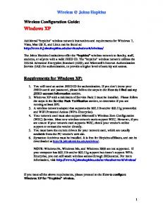
Configuring virtual servers When you create a virtual server, you specify the type of virtual server you want, that is, a host virtual server or a network virtual server. Then you can attach various properties and resources to it, such as application-specific profiles, session persistence, and user-written scripts called iRules that define pool-selection criteria. All of these properties and resources, when associated with a virtual server, determine how the LTM system manages local traffic. When you create and configure a virtual server, you use the part of the Configuration utility screen shown in Figure 1.1, on page 1-8.
Configuration Guide for Local Traffic Management
1-7
Chapter 1
Figure 1.1 The Configuration utility screen for creating a virtual server
For more information on virtual servers, see Chapter 2, Configuring Virtual Servers.
1-8
Introducing Local Traffic Management
Configuring load balancing pools A load balancing pool is a collection of internal servers that you group together to service client requests. A server in a pool is referred to as a pool member. Using the default load balancing algorithm, known as Round Robin, the LTM system sends a client request to a member of that pool. To implement a load balancing pool, you first create the pool, and then you associate the pool name with an existing virtual server. A virtual server sends client requests to the pool or pools that are associated with it. The virtual server screen shown in figure 1.1, on page 1-8 includes a setting, Default Pool, for specifying a pool name. Pools have settings associated with them, such as IP addresses for pool members, load balancing modes, and health and performance monitors. When you create a pool, you can use the default values for some of these settings, or change them to better suit your needs. When you create and configure a load balancing pool, you use the Pool screen of the Configuration utility. Figure 1.2 shows part of this screen.
Figure 1.2 The Configuration utility screen for creating a load balancing pool
Configuration Guide for Local Traffic Management
1-9
Chapter 1
For more information on load balancing pools, see Chapter 4, Configuring Load Balancing Pools.
Configuring profiles A profile is a group of configuration settings that apply to a specific type of network traffic, such as HTTP connections. If you want the virtual server to manage a type of traffic, you can associate the applicable profile with the virtual server, and the virtual server applies that profile’s settings to all traffic of that type. For example, you might want the LTM system to compress HTTP response data. In this case, you can configure an HTTP profile to enable compression, and associate the profile with a virtual server. Then, when the virtual server processes an HTTP request, the LTM system compresses the response. There are several types of profiles that you can create for your own needs. They are: FastL4, TCP, UDP, One Connect, Stream, HTTP, FTP, Client SSL, Server SSL, Persistence, and Authentication. When you create a profile, you can use the default values for the settings, or change them to better suit your needs. For example, when you create and configure an HTTP profile, you use the part of the Configuration utility screen shown in Figure 1.3, on page 1-11.
1 - 10
Introducing Local Traffic Management
Figure 1.3 The Configuration screen for creating an HTTP profile
For more information on configuring profiles, see Chapter 5, Understanding Profiles, and one of the following chapters: • Chapter 6, Managing HTTP and FTP Traffic • Chapter 7, Managing SSL Traffic • Chapter 8, Authenticating Application Traffic • Chapter 9, Enabling Session Persistence
Configuration Guide for Local Traffic Management
1 - 11
Chapter 1
Introduction to the Configuration Guide for Local Traffic Management This guide describes how to configure the BIG-IP local traffic management system to manage traffic coming into, or leaving, the local traffic network. Before you can configure the features described in this guide, you must install the BIG-IP system, license the system, and use the Setup utility to perform the management network configuration. For information about these tasks, refer to the Platform Guide: 1500, 3400, and 6400, and the Installation, Licensing, and Upgrades for BIG-IP Systems guide.
Using the Configuration utility All users need to use the web-based Configuration utility in order to license the system for the first time. In addition to setting up the management network and initial traffic management software configuration, you use the Configuration utility to configure and monitor the LTM system. You can use the Configuration utility to perform additional configuration steps necessary for your configuration. In the Configuration utility, you can also monitor current system performance. Most procedures in this guide use the Configuration utility. The Configuration utility supports Netscape® Navigator™, version 7.1, or other browsers built on the same engine, such as Mozilla™, Firefox™, and Camino™; and Microsoft® Internet Explorer™ version 6.x and later.
Additional information In addition to this guide, there are other sources of the documentation you can use in order to work with the BIG-IP system. The information is organized into the guides and documents described below. The following printed documentation is included with the BIG-IP system. ◆
Configuration Worksheet This worksheet provides you with a place to plan the basic configuration for the BIG-IP system.
◆
BIG-IP Quick Start Instructions This pamphlet provides you with the basic configuration steps required to get the BIG-IP system up and running in the network.
The following guides are available in PDF format from the CD-ROM provided with the BIG-IP system. These guides are also available from the first Web page you see when you log in to the administrative web server on the BIG-IP system.
1 - 12
Introducing Local Traffic Management
◆
Platform Guide This guide includes information about the BIG-IP system. It also contains important environmental warnings.
◆
Installation, Licensing, and Upgrades for BIG-IP Systems This guide provides detailed information about installing upgrades to the BIG-IP system. It also provides information about licensing the BIG-IP system software and connecting the system to a management workstation or network.
Stylistic conventions To help you easily identify and understand important information, our documentation uses the stylistic conventions described below.
Using the solution examples All examples in this documentation use only non-routable IP addresses. When you set up the solutions we describe, you must use IP addresses suitable to your own network in place of our sample addresses.
Identifying new terms To help you identify sections where a term is defined, the term itself is shown in bold italic text. For example, a virtual server is a specific combination of a virtual address and virtual port, associated with a content site that is managed by a BIG-IP system or other type of host server.
Identifying references to objects, names, and commands We apply bold text to a variety of items to help you easily pick them out of a block of text. These items include web addresses, IP addresses, utility names, and portions of commands, such as variables and keywords. For example, you can set the Idle Timeout value to 5.
Identifying references to other documents We use italic text to denote a reference to another document. In references where we provide the name of a book as well as a specific chapter or section in the book, we show the book name in bold, italic text, and the chapter/section name in italic text to help quickly differentiate the two. For example, for installation instuctions, refer to Chapter 1, Installing the Software, in the Installation, Licensing, and Upgrades for BIG-IP Systems guide.
Configuration Guide for Local Traffic Management
1 - 13
Chapter 1
Finding additional help and technical support resources You can find additional technical information about this product in the following locations: ◆
Release notes Release notes for the current version of this product are available from the product web server home page, and are also available on the technical support site. The release notes contain the latest information for the current version, including a list of new features and enhancements, a list of fixes, and, in some cases, a list of known issues.
◆
Online help You can find help online in three different locations: • The web server on the product has PDF versions of the guides included in the Software CD. • The web-based Configuration utility has online help for each screen. Simply click the Help tab.
◆
Ask F5 Technical Support web site The F5 Networks Technical Support web site, http://tech.f5.com, provides the latest documentation for the product, including technical notes, answers to frequently asked questions, updates for guides (in PDF format), and the Ask F5 natural language question and answer engine. To access this site, you need to register at http://tech.f5.com.
◆
F5 Solution Center The F5 Solution Center contains proven interoperability and integration solutions that empower organizations to deliver predictable and secure applications in an unpredictable network environment. The F5 Solution Center offers detailed documentation that demonstrates how to increase the return on investment (ROI) of your application and network infrastructures through superior reliability, security, and performance. You can access this site at http://www.f5.com/solutions. Note
All references to hardware platforms in this guide refer specifically to systems supplied by F5 Networks, Inc. If your hardware was supplied by another vendor and you have hardware-related questions, please refer to the documentation from that vendor.
1 - 14
2 Configuring Virtual Servers
• Introducing virtual servers • Understanding virtual server types • Creating and modifying virtual servers • Configuring virtual server and virtual address settings • Managing virtual servers and virtual addresses
Configuring Virtual Servers
Introducing virtual servers Virtual servers are the most important component of any BIG-IP® local traffic management (LTM) configuration. A virtual server receives a client request, and instead of sending the request directly to the destination IP address specified in the packet header, sends it to any of several content servers that make up a load balancing pool. Virtual servers increase the availability of resources for processing client requests. Not only do virtual servers distribute traffic across multiple servers, they also treat varying types of traffic differently, depending on your traffic-management needs. For example, a virtual server can enable compression on HTTP request data as it passes through the LTM system, or decrypt and re-encrypt SSL connections and verify SSL certificates. For each type of traffic, such as TCP, UDP, HTTP, SSL, and FTP, a virtual server can apply an entire group of settings, to affect the way that the LTM system manages that traffic type. A virtual server can also enable session persistence for many different traffic types. Through a virtual server, you can set up session persistence for HTTP, SSL, SIP, and MSRDP connections, to name a few. Finally, a virtual server can apply an iRule, which is a user-written script designed to inspect and direct individual connections in specific ways. For example, you can create an iRule that searches the content of a TCP connection for a specific string and, if found, directs the virtual server to send the connection to a specific pool or pool member. To summarize, a virtual server can do the following: • Distribute client requests across multiple servers to balance server load • Apply various behavioral settings to multiple traffic types • Enable persistence for multiple traffic types • Direct traffic according to user-written iRulesTM You can use virtual servers in any of several distinct ways: ◆
Directing traffic to a load balancing pool A Standard virtual server (also known as a load balancing virtual server) directs client traffic to a load balancing pool and is the most basic type of virtual server. When you first create the virtual server, you assign an existing default pool to it. From then on, the virtual server automatically directs traffic to that default pool.
◆
Sharing an IP address with a VLAN node You can set up a Forwarding (Layer 2) virtual server to share the same IP address as a node in an associated VLAN. To do this, you must perform some additional configuration tasks. These tasks consist of: creating a VLAN group that includes the VLAN in which the node resides, assigning a self-IP address to the VLAN group, and disabling the virtual server on the relevant VLAN. For more information, see the chapter that describes VLANs and VLAN groups in the Network and System Management Guide.
Configuration Guide for Local Traffic Management
2-1
Chapter 2
◆
Forwarding traffic to a specific destination IP address A Forwarding (IP) virtual server is just like other virtual servers, except that the virtual server has no pool members to load balance. The virtual server simply forwards the packet directly to the destination IP address specified in the client request. When you use a forwarding virtual server to direct a request to its originally-specified destination IP address, the LTM system adds, tracks, and reaps these connections just as with other virtual servers. You can also view statistics for a forwarding virtual servers.
◆
Increasing the speed of processing HTTP traffic A Performace (HTTP) virtual server is a virtual server with which you associate a Fast HTTP profile. Together, the virtual server and profile increase the speed at which the virtual server processes HTTP requests.
◆
Increasing the speed of processing layer 4 traffic A Performance (Layer 4) virtual server is a virtuals erver which you associate a Fast L4 profile. Together, the virtual server and profile increase the spped at which the virtual server processes layer 4 requests.
When you create a virtual server, you specify the pool or pools that you want to serve as the destination for any traffic coming from that virtual server. You also configure its general properties, some configuration options, and other resources you want to assign to it, such as iRules or session persistence types. The following sections describe the types of virtual servers you can create, as well as their general properties, configuration options, and resources.
2-2
Configuring Virtual Servers
Understanding virtual server types There are two distinct types of virtual servers that you can create: host virtual servers and network virtual servers.
Host virtual servers A host virtual server represents a specific site, such as an Internet web site or an FTP site, and it load balances traffic targeted to content servers that are members of a pool. The IP address that you assign to a host virtual server should match the IP address that DNS associates with the site’s domain name. When the LTM system receives a connection request for that site, the LTM system recognizes that the client’s destination IP address matches the IP address of the virtual server, and subsequently forwards the client request to one of the content servers that the virtual server load balances.
Network virtual servers A network virtual server is a virtual server whose IP address has no bits set in the host portion of the IP address (that is, the host portion of its IP address is 0). There are two kinds of network virtual servers: those that direct client traffic based on a range of destination IP addresses, and those that direct client traffic based on specific destination IP addresses that the LTM system does not recognize.
Directing traffic for a range of destination IP addresses With an IP address whose host bit is set to 0, a virtual server can direct client connections that are destined for an entire range of IP addresses, rather than for a single destination IP address (as is the case for a host virtual server). Thus, when any client connection targets a destination IP address that is in the network specified by the virtual server IP address, the LTM system can direct that connection to one or more pools associated with the network virtual server. For example, the virtual server can direct client traffic that is destined for any of the nodes on the 192.168.1.0 network to a specific load balancing pool such as ingress-firewalls. Or, a virtual server could direct a web connection destined to any address within the subnet 192.168.1.0/24, to the pool default_webservers.
Configuration Guide for Local Traffic Management
2-3
Chapter 2
Directing traffic for transparent devices (wildcard virtual servers) Besides directing client connections that are destined for a specific network or subnet, a network virtual server can also direct client connections that have a specific destination IP address that the virtual server does not recognize, such as a transparent device. This type of network virtual server is known as a wildcard virtual server. Wildcard virtual servers are a special type of network virtual server designed to manage network traffic that is targeted to transparent network devices. Examples of transparent devices are firewalls, routers, proxy servers, and cache servers. A wildcard virtual server manages network traffic that has a destination IP address unknown to the LTM system.
Handling unrecognized client IP addresses A host-type of virtual server typically manages traffic for a specific site, When the LTM system receives a connection request for that site, the LTM system recognizes that the client’s destination IP address matches the IP address of the virtual server, and it subsequently forwards the client to one of the content servers that the virtual server load balances. However, when load balancing transparent nodes, the LTM system might not recognize a client’s destination IP address. The client might be connecting to an IP address on the other side of the firewall, router, or proxy server. In this situation, the LTM system cannot match the client’s destination IP address to a virtual server IP address. Wildcard network virtual servers solve this problem by not translating the incoming IP address at the virtual server level on the LTM system. For example, when the LTM system does not find a specific virtual server match for a client’s destination IP address, the LTM system matches the client’s destination IP address to a wildcard virtual server, designated by an IP address of 0.0.0.0. The LTM system then forwards the client’s packet to one of the firewalls or routers that the wildcard virtual server load balances, which in turn forwards the client’s packet to the actual destination IP address.
Understanding default and port-specific wildcard servers There are two kinds of wildcard virtual servers that you can create: ◆
2-4
Default wildcard virtual servers A default wildcard virtual server is a wildcard virtual server that uses port 0 and handles traffic for all services. A wildcard virtual server is enabled for all VLANs by default. However, you can specifically disable any VLANs that you do not want the default wildcard virtual server to support. Disabling VLANs for the default wildcard virtual server is done by creating a VLAN disabled list. Note that a VLAN disabled list applies to default wildcard virtual servers only. You cannot create a VLAN disabled list for a wildcard virtual server that is associated with one VLAN only. For the procedure to create a default wildcard server, see Creating a wildcard virtual server, on page 2-7.
Configuring Virtual Servers
◆
Port-specific wildcard virtual servers A port-specific wildcard virtual server handles traffic only for a particular service, and you define it using a service name or a port number. You can use port-specific wildcard virtual servers for tracking statistics for a particular type of network traffic, or for routing outgoing traffic, such as HTTP traffic, directly to a cache server rather than a firewall or router. For the procedure to create a port-specific wildcard virtual server, see To create a port-specific wildcard virtual server, on page 2-8.
If you use both a default wildcard virtual server and port-specific wildcard virtual servers, any traffic that does not match either a standard virtual server or one of the port-specific wildcard virtual servers is handled by the default wildcard virtual server. We recommend that when you define transparent nodes that need to handle more than one type of service, such as a firewall or a router, you specify an actual port for the node and turn off port translation for the virtual server.
Creating multiple wildcard servers You can define multiple wildcard virtual servers that run simultaneously. Each wildcard virtual server must be assigned to an individual VLAN, and therefore can handle packets for that VLAN only. In some configurations, you need to set up a wildcard virtual server on one side of the LTM system to load balance connections across transparent devices. You can create another wildcard virtual server on the other side of the LTM system to forward packets to virtual servers receiving connections from the transparent devices and forwarding them to their destination.
Configuration Guide for Local Traffic Management
2-5
Chapter 2
Creating and modifying virtual servers Using the Configuration utility, you can either create a virtual server or modify the settings of an existing virtual server. The following sections contain the procedures for creating and modifying virtual servers. To understand individual virtual server properties and settings, see Configuring virtual server and virtual address settings, on page 2-10. For information on viewing existing virtual server configurations, see Managing virtual servers and virtual addresses, on page 2-15.
Creating a virtual server When you create a virtual server, you can create either a host or network virtual server, or a special type of network virtual server called a wildcard virtual server.
Creating a host or network virtual server You can use the same procedure to create both a host virtual server and a network virtual server. The following procedure creates the most basic host or network virtual server, with all of the default settings. After performing this procedure, you have a load-balancing virtual server that directs traffic to a load balancing pool, using the default settings. In most cases, creating a basic virtual server satisfies your load balancing or forwarding needs. When you create a basic virtual server, most of the settings are hidden, to simplify the creation process. If you want to adjust other settings beyond the basic ones, you can view and configure more advanced settings. For information on configuring specific settings, see Configuring virtual server and virtual address settings, on page 2-10, or see the online help. Note
In a redundant-system configuration, you cannot create a vitual server for unit 2 unless you have first created a virtual server for unit 1.
To create a host or network virtual server 1. On the Main tab, expand Local Traffic. 2. Click Virtual Servers. The Virtual Servers screen displays. 3. On the upper right portion of the screen, click the Create button. The New Virtual Server screen opens. 4. Configure all required settings. If you are creating a network virtual server, you must set the host bit of the IP address to 0. 5. Retain or change the values for any optional settings.
2-6
Configuring Virtual Servers
6. Click Finished Note
If a virtual server is to have the same IP address as a node in an associated VLAN, you must perform some additional configuration tasks. These tasks consist of: creating a VLAN group that includes the VLAN in which the node resides, assigning self-IP addresses to the VLAN group, and disabling the virtual server on the relevant VLAN. For more information, see the online help pertaining to VLANs.
Creating a wildcard virtual server A wildcard virtual server is a special type of network virtual server. Creating a wildcard virtual server requires three tasks: • First, you must create a pool that contains the addresses of the transparent devices. • Next, you must create the wildcard virtual server (default or port-specific). • Finally, you must ensure that port translation is disabled for each virtual server. Port translation is disabled by default. The following procedures describe how to perform these tasks using the Configuration utility.
To create a pool of transparent devices To create a pool of transparent devices, display the Pools screen and click the Create button. For more information, see Chapter 4, Configuring Load Balancing Pools.
To create a default wildcard virtual server 1. On the Main tab, expand Local Traffic. 2. Click Virtual Servers. The Virtual Servers screen opens. 3. On the upper right portion of the screen, click the Create button. The New Virtual Server screen opens. 4. Configure all required settings. Remember to type the IP address 0.0.0.0 in the Destination Address box, and if you selected a network type of virtual server, to type the netmask 0.0.0.0 in the Mask box. 5. Click Finished.
Configuration Guide for Local Traffic Management
2-7
Chapter 2
To create a port-specific wildcard virtual server 1. On the Main tab, expand Local Traffic. 2. Click Virtual Servers. The Virtual Servers screen opens. 3. On the upper-right portion of the screen, click Create. The New Virtual Server screen opens. 4. In the Address box, type the wildcard IP address 0.0.0.0. 5. For the Service Port setting, type a port number, or select a service name from the list. Note that port 0 defines a wildcard virtual server that handles all types of services. If you specify a port number, you create a port-specific wildcard virtual server. The wildcard virtual server handles traffic only for the port specified. 6. For the Default Pool setting in the Resources section, select the pool of transparent devices that you want to apply to the virtual server. 7. Click Finished.
To turn off port translation for a wildcard virtual server After you define the wildcard virtual server with a wildcard port, you should verify that port translation is disabled for the virtual server. 1. On the Main tab, expand Local Traffic. 2. Click Virtual Servers. The Virtual Servers screen opens. 3. In the Name column, click the virtual server for which you want to turn off port translation. The Virtual Servers screen opens. 4. In the Enable Translation section, verify that the Port box is cleared.
Modifying a virtual server You can easily modify the settings of an existing virtual server, using the Configuration utility. For information on virtual settings, see Configuring virtual server and virtual address settings, on page 2-10 or the online help.
To modify an existing virtual server 1. On the Main tab, expand Local Traffic. 2. Click Virtual Servers. The Virtual Servers screen opens.
2-8
Configuring Virtual Servers
3. In the Name column, click the name of the virtual server that you want to modify. The properties screen opens for that virtual server. 4. From the Configuration list, select Advanced. 5. In the Configuration section, retain or modify any virtual server settings. 6. Click Update. 7. On the menu bar, click Resources. The screen displays additional settings for the selected virtual server. 8. In the Load Balancing section, retain or modify any virtual server resources. 9. Click Update. 10. If you want to modify the set of iRules assigned to the virtual server, click the Manage button, and use the left or right arrows (>) to enable or disable any existing iRules. 11. Click Finished.
Configuration Guide for Local Traffic Management
2-9
Chapter 2
Configuring virtual server and virtual address settings A virtual server and its virtual server address have a number of properties and settings that you can configure to affect the way that a virtual server manages traffic. You can also assign certain resources to a virtual server, such as a load balancing pool and a persistence profile. Together, these properties, settings, and resources represent the definition of a virtual server or its address, and most have default values. When you create a virtual server, you can either retain the default values or adjust them to suit your needs. The following sections list and describe all properties, configuration settings, and resources that define virtual servers and virtual addresses. For information on how to create virtual server, see Creating a host or network virtual server, on page 2-6.
Configuring virtual server properties, settings, and resources In the Configuration utility, virtual server settings are grouped into three categories: General properties, configuration settings (basic and advanced), and resources (basic and advanced). The following sections describe the settings that these three categories contain.
General properties When you create a virtual server, you define some general properties. Table 2.1 lists and describes these general properties. Property
Description
Default Value
Name
A unique name that you assign to the virtual server. This property is required.
No default value
Destination Type
The type of virtual server you want to create and its IP address. If the type you select is network, then this property also includes the mask for the IP address. For more information on virtual server types, see Understanding virtual server types, on page 2-3. This property is required.
Host
Destination Address
The IP address of the virtual server.
No default value
Table 2.1 General properties of a virtual server
2 - 10
Configuring Virtual Servers
Property
Description
Default Value
Destination Mask
The netmask for a network virtual server. This property applies to a network virtual server only, and is required. The netmask clarifies whether the host bit is an actual zero or a wildcard representation.
No default value
Service Port
A service name or port number for which you want to direct traffic. This property is required.
No default value
State
The state of the virtual server, that is, enabled or disabled. As an option, you can enable or disable a virtual server for a specific VLAN. Note that when you disable a virtual server, the virtual server no longer accepts new connection requests. However, it allows current connections to finish processing before going to a down state.
Enabled
Note: If no VLAN is specified, then the enabled or disabled setting applies to all VLANs.
Table 2.1 General properties of a virtual server
Configuration settings When creating a virtual server, you can configure a number of settings. Table 2.2 lists and describes these virtual server configuration settings. Because all of these settings have default values, you are not required to change these settings. Setting
Description
Default Value
Type
The type of virtual server configuration. Choices are: Standard, IP Forwarding (IP), Forwarding (Layer 2), Performance (HTTP), Performance (Layer 4), and Reject. For more information, see Introducing virtual servers, on page 2-1. Note that if set to Reject, this setting causes the BIG-IP system to reject any traffic destined for the virtual server IP address.
Standard
Protocol
The network protocol name for which you want the virtual server to direct traffic. Sample protocol names are TCP and UDP.
TCP
One benefit of this feature is that you can load balance virtual private network (VPN) client connections across several VPNs, eliminating the possibility of a single point of failure. A typical use of this feature is for load balancing multiple VPN gateways in an IPSEC VPN sandwich, using non-translating virtual servers. An important point to note is that although address translation of such protocols can be optionally activated, some protocols, such as IPSEC in AH mode, rely on the IP headers remaining unchanged. In such cases, you should use non-translating network virtual servers. Note that this setting is disabled when creating a Performance (HTTP) type of virtual server. Protocol Profile (Client)
A setting that designates the selected profile as a client-side profile. Applies to TCP and UDP connections only. When creating a Performance (HTTP) type of virtual server, this value is set to fasthttp, and you cannot change it. Similarly, when creating a Performance (Layer 4) type of virtual server, this value is set to fastl4, and you cannot change it.
TCP
Table 2.2 Configuration settings for a virtual server
Configuration Guide for Local Traffic Management
2 - 11
Chapter 2
Setting
Description
Default Value
Protocol Profile (Server)
A setting that designates the selected profile as a server-side profile. Applies to TCP and UDP connections only. Note that this setting does not appear when creating a Performance (HTTP) or Performance (Layer 4) type of virtual server.
(Use Client Profile)
OneConnect Profile
The name of an existing OneConnect profile for managing connection persistence. Note that this setting does not appear when creating a Performance (HTTP) or Performance (Layer 4) type of virtual server.
oneconnect
HTTP Profile
The name of an existing HTTP profile for managing HTTP traffic.Note that this setting does not appear when creating a Performance (HTTP) or Performance (Layer 4) type of virtual server.
None
FTP Profile
The name of an existing FTP profile for managing FTP traffic.Note that this setting does not appear when creating a Performance (HTTP) or Performance (Layer 4) type of virtual server.
None
Client SSL Profile
The name of an existing SSL profile for managing client-side SSL traffic.Note that this setting does not appear when creating a Performance (HTTP) or Performance (Layer 4) type of virtual server.
None
Server SSL Profile
The name of an existing SSL profile for managing server-side SSL traffic.Note that this setting does not appear when creating a Performance (HTTP) or Performance (Layer 4) type of virtual server.
None
Authentication Profile
The name of an existing authentication profile for managing an authentication mechanism. Examples are a remote LDAP or RADIUS server. Note that this setting does not appear when creating a Performance (HTTP) or Performance (Layer 4) type of virtual server.
None
Stream Profile
The name of an existing Stream profile for managing Real-Time Streaming Protocol (RTSP) traffic.Note that this setting does not appear when creating a Performance (HTTP) or Performance (Layer 4) type of virtual server.
None
Statistics Profile
The name of a statistics profile.
stats
VLAN Traffic
The names of VLANS for which the virtual server is enabled or disabled.
ALL VLANS
Rate Class
The name of an existing rate class, used for enforcing a throughput policy on incoming network traffic.
None
Connection Limit
The maximum number of concurrent connections allowed for the virtual server. Setting this to 0 turns off connection limits.
0
Address Translation
A setting to enable or disable address translation on an LTM system. This option is useful when the LTM system is load balancing devices that have the same IP address. This is typical with the nPath routing configuration where duplicate IP addresses are configured on the loopback device of several servers.
Enabled
Port Translation
A setting to enable or disable port translation on an LTM system. Turning off port translation for a virtual server is useful if you want to use the virtual server to load balance connections to any service.
Enabled
SNAT Pool
The name of an existing SNAT pool, used for implementing selective and intelligent SNATs.
Table 2.2 Configuration settings for a virtual server
2 - 12
None
Configuring Virtual Servers
Setting
Description
Clone Pool (Client)
A feature that causes the virtual server to replicate client-side traffic (that is, prior to address translation), to a member of the specified clone pool. This feature is used for intrusion detection. You can also configure the Clone Pool (Server) setting.
Clone Pool (Server)
A feature that causes the virtual server to replicate server-side traffic (that is, after address translation), to a member of the specified clone pool. This feature is used for intrusion detection.You can also configure the Clone Pool (Client) setting.
Last Hop Pool
A setting that directs reply traffic to the last hop router using a last hop pool. This overrides the auto_lasthop setting. In cases where you have more than one router sending connections to the LTM system, connections are automatically sent back through the same router from which they were received when the auto_lasthop global variable is enabled, as it is by default. If you want to exclude one or more routers from auto-lasthop, or if the global auto_lasthop is disabled for any reason (for example, you may not want it for an SSL gateway), you can use a last hop pool instead. (If auto_lasthop is enabled, the last hop pool takes precedence over it.)
Default Value None
None
None
Before configuring a last hop pool, you must first create a pool containing the router inside addresses.
Table 2.2 Configuration settings for a virtual server
Resources If you have created a load balancing virtual server, you must assign a default load balancing pool to it. If you plan on using an iRule to direct certain kinds of traffic, you must also assign the iRule to the virtual server, as well as to any pools that are specified within the iRule. These pool and iRule assignments are known as resources. Table 2.3 lists and describes the specific resources that you can assign to a load balancing virtual server. Resource
Description
Default Value
Default Pool
The pool name that you would like the virtual server to use as the default pool. A load balancing virtual server sends traffic to this pool automatically, unless an iRule directs the server to send the traffic to another pool instead.
No default value
Table 2.3 Resources assigned to a load balancing virtual server
Configuration Guide for Local Traffic Management
2 - 13
Chapter 2
Resource
Description
Default Value
Default Persistence Profile
The type of persistence that you want the LTM system to use.
None
Fallback Persistence Profile
The type of persistence that the LTM system should use if it cannot use the specified default persistence.
None
iRules
A list of existing iRules that you want the virtual server to use when load balancing its connections. Note that for all iRules that you select, you must configure a corresponding profile on the virtual server. For example, if you are specifying an iRule that includes HTTP commands, you must configure a default or custom HTTP profile on the virtual server. Similarly, if you are implementing an authentication iRule, you must configure a default or custom authentication profile.
No default value
If the iRule you want to implmement does not appear in the iRules list, the iRule does not exist and you must first create it. If the iRules setting does not appear on the New Virtual Server screen, check your licensing.
Table 2.3 Resources assigned to a load balancing virtual server
Configuring virtual address properties and settings The Configuration utility displays virtual address properties and settings. Table 2.4 lists and describes the general properties and configuration settings of a virtual address. Property
Description
Default Value
Address
The IP address of the virtual server, not including the service.
No default value
State
The state of the virtual address, that is, enabled or disabled.
Enabled
Connection limit
The number of concurrent connections that the LTM system allows on this virtual address.
0
ARP
A setting that enables or disables ARP requests.
Enabled
Table 2.4 General properties and configuration settings of a virtual address
2 - 14
Configuring Virtual Servers
Managing virtual servers and virtual addresses When generally managing virtual servers and virtual addresses, you typically need to view existing virtual server or virtual address configurations. Occasionally, too, you might need to delete a virtual server. When working with virtual servers that you have created, you can: • View a virtual server configuration • View a virtual address configuration • Delete a virtual server
Viewing a virtual server configuration Occassionally, you might want to determine whether you need to adjust virtual server settings, or create new virtual servers. When you view a virtual server configuration, you can view: • A list of virtual servers • Virtual server properties and settings • Virtual server resources • Virtual server statistics
Viewing a list of virtual servers You can view a list of existing virtual servers that you have created. When you display the list of virtual servers, the Configuration utility displays the following information about each virtual server: • Status • Virtual server name • Destination (virtual address) • Service Port • Protocol • Resource type (load balancing, forwarding, or L2 forwarding)
To view a list of virtual servers 1. On the Main tab, expand Local Traffic. 2. Click Virtual Servers. A list of all existing virtual servers appears.
Configuration Guide for Local Traffic Management
2 - 15
Chapter 2
Viewing virtual server properties and settings You can view virtual server properties, such as the profile types that are assigned to the virtual server.
To view virtual server properties 1. On the Main tab, expand Local Traffic. 2. Click Virtual Servers. A list of all existing virtual servers appears. 3. In the Name column, click a virtual server name. This displays the properties for that virtual server.
Viewing virtual server resources You can view the default pool, default persistence profile, and fallback persistence profile that are assigned as resources to the virtual server. You can also view any iRules associated with the virtual server. The following procedure shows how to view these resources.
To view virtual server resources 1. On the Main tab, expand Local Traffic. 2. Click Virtual Servers. A list of all existing virtual servers appears. 3. Click a virtual server name. This displays the properties for that virtual server. 4. Click the Resources menu. This displays the resources assigned to the virtual server.
Viewing virtual server statistics Using the Configuration utility, you can view statistics for any existing virtual servers.
To view statistics for a virtual server 1. On the Main tab, expand Local Traffic. 2. Click Virtual Servers. A list of all existing virtual servers appears. 3. In the Name column, click the name of a virtual server. 4. From the Statistics menu, choose Virtual Server. This displays the statistics for the virtual server.
2 - 16
Configuring Virtual Servers
Viewing a virtual address configuration Occassionally, you might want to view virtual address settings, to determine whether you need to adjust them. In working with virtual address configurations, you can view: • A list of virtual addresses • Virtual address properties • Virtual address statistics
Viewing a list of virtual addresses You can view a list of existing virtual addresses that you have created, and adjust any of their settings. When you display the list of virtual addresses, the Configuration utility also displays the state of that address (enabled or disabled).
To view a list of virtual addresses 1. On the Main tab, expand Local Traffic. 2. Click Virtual Servers. By default, a list of all existing virtual servers appears. 3. On the menu bar, click Virtual Address List. A list of all existing virtual addresses appears.
Viewing virtual address properties The following procedure shows how to view virtual address properties.
To view or adjust virtual address properties 1. Display the list of existing virtual addresses, using the previous procedure. 2. Click a virtual address. This displays the properties for that virtual address.
Viewing virtual address statistics Using the Configuration utility, you can view statistics for any existing virtual addresses.
To view statistics for a virtual address 1. On the Main tab, expand Local Traffic. 2. Click Virtual Servers. By default, a list of all existing virtual servers appears.
Configuration Guide for Local Traffic Management
2 - 17
Chapter 2
3. On the menu bar, click Virtual Address List. A list of all existing virtual addresses appears. 4. From the Statistics menu, choose Virtual Address. This displays statistics for the virtual address.
Deleting a virtual server You can permanently delete a virtual server and its virtual address from a configuration.
To delete a virtual server 1. On the Main tab, expand Local Traffic. 2. Click Virtual Servers. This displays a list of existing virtual servers. 3. Check the Select box to the left of any virtual server that you want to delete. 4. Click Delete. This displays the Delete Confirmation screen. 5. Click Delete. This removes the virtual server.
2 - 18
3 Configuring Nodes
• Introducing nodes • Creating and modifying nodes • Configuring node settings • Managing nodes
Configuring Nodes
Introducing nodes Nodes are the network devices to which a BIG-IP® local traffic management (LTM) system passes traffic. You can explicitly create a node, or you can instruct the LTM system to automatically create one when you add a pool member to a load balancing pool. The difference between a node and a pool member is that a node is designated by the device’s IP address only (10.10.10.10), while designation of a pool member includes an IP address and a service (such as 10.10.10:80). A primary feature of nodes is their association with health monitors. Like pool members, nodes can be associated with health monitors as a way to determine server status. However, a health monitor for a pool member reports the status of a service running on the device, whereas a health monitor associated with a node reports status of the device itself. For example, if an ICMP health monitor is associated with node 10.10.10.10, which corresponds to pool member 10.10.10.10:80, and the monitor reports the node as being in a down state, then the monitor also reports the pool member as being down. Conversely, if the monitor reports the node as being in an up state, then the monitor reports the pool member as being either up or down, depending on the status of the service running on it. You create a node using the Configuration utility, and then adjust the settings as needed. Using the same utility, you can also display information about nodes, enable and disable nodes, and delete nodes.
Configuration Guide for Local Traffic Management
3-1
Chapter 3
Creating and modifying nodes Nodes are the basis for creating a load balancing pool. For any server that you want to be part of a load balancing pool, you must first create a node, that is, designate that server as a node. After designating the server as node, you can add the node to a pool as a pool member. You can also associate a health monitor with the node, to report the status of that server. For information on adding nodes to load balancing pools, see Chapter 4, Configuring Load Balancing Pools. You use the Configuration utility to create a node. When you create a node, the LTM system automatically assigns a group of default settings to that node. You can retain these default settings or modify them. You can also modify the settings at a later time, after you have created the node. For information on these settings, see either Configuring node settings, on page 3-3, or the online help. It is helpful to understand that the LTM system designates some settings as basic and others as advanced. If you decide to modify some of the default settings when you create the node, be sure to select the Advanced option on the screen to view all configurable settings. For more information on basic and advanced settings, see Chapter 1, Introducing Local Traffic Management.
To create a node 1. On the Main tab, expand Local Traffic. 2. Click Nodes. The Nodes screen opens. 3. In the upper-right corner of the screen, click Create. The New Node screen opens. 4. For the Address setting, type the IP address of the node. 5. Specify, retain, or change each of the other settings. 6. Click Finished.
To modify an existing node 1. On the Main tab, expand Local Traffic. 2. Click Nodes. The Nodes screen opens. 3. In the Address column, click an address. This displays the settings for that node. 4. Retain or modify any node settings. 5. Click Update.
3-2
Configuring Nodes
Configuring node settings You can configure node settings to tailor nodes to your specific needs. For those settings that have default values, you can retain those default settings or modify them. Also, you can modify settings either when you create the node, or at any time after you have created it. Table 3.1 lists these configurable settings and their default values. Following this table are descriptions of specific settings. Node settings
Description
Default Value
Address
Specifies the IP address of the node. This setting is required.
No default value
Name
Specifies the name of the node.
No default value
Health Monitors
Associates a health or performance monitor with a node.
No default value
Select Monitors
Specifies the monitors that the LTM system is to associate with the node.
No default value
Availability Requirement
Specifies the minimum number of health monitors that must report a node as being available to receive traffic before the LTM system reports that node as being in an up state.
All
Ratio
Specifies the ratio weight you want to assign to the node.
1
Connection Limit
Specifies the maximum number of concurrent connections allowed on a node.
0
Table 3.1 Node configuration settings
Before configuring a node, it is helpful to have a description of certain node settings that you might want to change.
Specifying an address for a node For each node that you configure, you must specify an IP address. An example of a node IP address is 10.10.10.10. This is the only required setting.
Specifying a node name For each node that you configure, you can give it a unique node name, such as Node_1. Node names are case-sensitive and may contain letters, numbers, and underscores (_) only. Reserved keywords are not allowed.
Configuration Guide for Local Traffic Management
3-3
Chapter 3
Specifying monitor associations Using the LTM system, you can monitor the health of performance of your nodes by associating health or performance monitors with those nodes. This is similar to associating a monitor with a load balancing pool, except that in the case of nodes, you are monitoring the IP address, whereas with pools, you are monitoring the services that are active on the pool members. The LTM system contains many different pre-configured monitors that you can associate with nodes, depending on the type of traffic you want to monitor. You can also create your own custom monitors and associate them with nodes. The only pre-configured monitors that are not available for associating with nodes are monitors that are specifically designed to monitor pools or pool members rather than nodes. There are two ways that you can associate a monitor with a node, by assigning the same monitor to multiple nodes at the same time, or by explicitly associating a monitor with each node as you create it. Note
If you use the bigpipe utility commands node and save to assign the same monitor to multiple nodes (for example, bigpipe node all monitor icmp and bigpipe save), the system creates a separate monitor-node entry in the bigip.conf file for each node. For more information on health and performance monitors, see Chapter 10, Configuring Monitors.
Creating a default monitor association You can configure the LTM system to automatically associate one or more monitor types with every node that you create. In this case, you choose the monitors before you create your nodes, and then by default, the LTM associates those monitors with every node that you create. This eliminates the task of having to explicitly associate monitors with each node that you create. You designate the default monitor for your nodes by navigating to the Nodes page and using the Default Monitor menu. Then when you create your node, you can set the value of the Health Monitors setting to Node Default. Note
If you want to assign a default monitor to an existing node, you can use the same Default Monitor menu to do this.
3-4
Configuring Nodes
Explicitly associating monitors with a node Instead of configuring the LTM system to automatically associate one or more monitors with every node that you create, you can associate specific monitors with a node when you create that node. You associate a monitor to a specific node (instead of all nodes as in the case of default monitor associations) by setting the value of the Health Monitors setting to Node Specific when you create a node or modify a node’s settings. The Configuration utility then allows you to choose from a list of monitors that are available for associating with that node.
Specifying the availability requirement By configuring the Availability Requirement setting, you can specify the minimum number of health monitors that must report a node as being available to receive traffic before the LTM system reports that node as being in an up state. Acceptable values are All or a number that you specify. If you choose the value At Least, you then specify a number.
Specifying a ratio weight The Ratio setting specifies a ratio weight for the node. The default setting is 1. For information on ratio weights, see Chapter 4, Configuring Load Balancing Pools.
Setting a connection limit Using the Connection Limit setting, you can specify the maximum number of concurrent connections allowed for a node. Note that the default value of 0 (zero) means that there is no limit to the number of concurrent connections that the node can receive.
Configuration Guide for Local Traffic Management
3-5
Chapter 3
Managing nodes After you have created your nodes and configured their settings to suit your needs, you might want to perform some additional management tasks. You can manage existing nodes in these ways: • Viewing existing nodes • Enabling or disabling existing nodes • Deleting existing nodes • Disabling monitor associations • Displaying node status
Viewing existing nodes You can use the following procedure to view nodes that you have created.
To view existing nodes 1. On the Main tab, expand Local Traffic. 2. Click Nodes. This displays a list of existing nodes. 3. In the Address column, click the address of the node you want to view. This displays the settings for that node.
Enabling and disabling a node A node must be enabled in order to accept traffic. When a node is disabled, the LTM system allows existing connections to time out or end normally. In this case, the node can accept new connections only if the connections belong to an existing persistence session. (In this way a disabled node differs from a node that is set to down. The down node allows existing connections to time out, but accepts no new connections.)
To enable or disable a node 1. On the Main tab, expand Local Traffic. 2. Click Nodes. This displays a list of existing nodes. 3. Locate the address of the node you want to enable or disable. 4. In the column to the left, check the Select box. 5. At the bottom of the screen, click the Enable or Disable button.
3-6
Configuring Nodes
Deleting a node If you are no longer using a node in a pool, you can delete the node.
To delete a node 1. On the Main tab, expand Local Traffic. 2. Click Nodes. This displays a list of existing nodes. 3. Locate the address of the node you want to enable or disable. 4. In the column to the left, check the Select box. 5. On the bottom of the screen, click Delete. A confirmation screen appears. 6. Click Delete.
Removing monitor associations Using the Configuration utility, you can remove a monitor that is explicitly associated with a specific node. When removing a monitor associated with a specific node, you can either remove the monitor association altogether, or change it so that only the default monitor is associated with the node. Alternatively, you can also remove any default monitors, that is, monitors that the LTM system automatically associates with any node that you create. For more information on monitor associations, see Specifying monitor associations, on page 3-4.
To remove an explicit monitor association for a node 1. On the Main tab, expand Local Traffic. 2. Click Nodes. This displays a list of existing nodes. 3. Click the address of the node you want to manage. 4. In the Configuration section of the screen, locate the Health Monitors setting. 5. Select Node Default or None. 6. Click Update.
Configuration Guide for Local Traffic Management
3-7
Chapter 3
To remove a default monitor 1. On the Main tab, expand Local Traffic. 2. Click Nodes. This displays a list of existing nodes. 3. Click the Default Monitor menu. 4. Using the right arrows (>>), move any active monitors from the Active box to the Available box. 5. Click Update.
Displaying node status The Nodes screen automatically displays the status of all existing nodes. Available status values are: • All • Available • Unavailable • Offline • Unknown
3-8
4 Configuring Load Balancing Pools
• Introducing load balancing pools • Creating and modifying load balancing pools • Configuring pool settings • Configuring pool member settings • Managing pools and pool members
Configuring Load Balancing Pools
Introducing load balancing pools In a typical client-server scenario, a client request goes to the destination IP address specified in the header of the request. For sites with a large amount of incoming traffic, the destination server can quickly become overloaded as it tries to service a large number of requests. To solve this problem, the BIG-IP® local traffic management (LTM) system distributes client requests to multiple servers instead of to the specified destination IP address only. You configure the LTM system to do this when you create a load balancing pool.
What is a load balancing pool? A load balancing pool is a set of devices, such as web servers, that you group together to receive and process traffic. Instead of sending client traffic to the destination IP address specified in the client request, the LTM system sends the request to any of the servers that are members of that pool. When you create a pool, you assign servers (known as pool members) to the pool, and then associate the pool with a virtual server in the LTM system. The LTM system then directs traffic coming into the virtual server to a member of that pool. An individual server can belong to one or multiple pools, depending on how you want to manage your network traffic. The specific pool member to which the LTM system chooses to send the request is determined by the load balancing method that you have assigned to that pool. A load balancing method is an algorithm that the LTM system uses to select a pool member for processing a request. For example, the default load balancing method is Round Robin, which causes the LTM system to send each incoming request to the next available member of the pool, thereby distributing requests evenly across the servers in the pool. For a complete list of load balancing methods, see Specifying the load balancing method, on page 4-10.
Features of a load balancing pool You can configure the LTM system to perform a number of different operations for a pool. You can: • Associate health monitors with pools and pool members • Enable or disable SNAT connections • Rebind a connection to a different pool member if the originally-targeted pool member becomes unavailable • Set the Quality of Service or Type of Service level within a packet • Specify a load balancing algorithm for a pool • Assign pool members to priority groups within a pool
Configuration Guide for Local Traffic Management
4-1
Chapter 4
Creating and modifying load balancing pools You use the Configuration utility to create a load balancing pool, or to modify a pool and its members. When you create a pool, the LTM system automatically assigns a group of default settings to that pool and its members. You can retain these default settings or modify them. Also, you can modify the settings at a later time, after you have created the pool. It is helpful to understand that the LTM system designates some settings as basic and others as advanced. If you decide to modify some of the default settings when you create the pool, be sure to select the Advanced option on the screen to view all configurable settings. For more information on basic and advanced settings in general, see Chapter 1, Introducing Local Traffic Management.
Creating and implementing a load balancing pool Creating and implementing a load balancing pool is a two-task process: • First, you must create the pool. • Second, you must associate the pool with a virtual server.
To create a load balancing pool 1. On the Main tab, expand Local Traffic. 2. Click Pools. The Pools screen opens. 3. In the upper-right corner of the screen, click Create. The New Pool screen opens. 4. From the Configuration list, select Advanced. 5. For the Name setting, type a name for the pool. 6. Specify, retain, or change each of the other settings. For information on pool settings, see Configuring pool settings, on page 4-5, or refer to the online help for this screen. 7. Click Finished.
To implement a load balancing pool 1. On the Main tab, click Virtual Servers. The Virtual Servers screen opens. 2. Click the name of the appropriate virtual server. This displays the settings for that virtual server. 3. On the menu bar, click Resources. 4. In the Default Pool list, select the name of your newly-created pool. 5. Click Update.
4-2
Configuring Load Balancing Pools
Modifying a load balancing pool You can modify any settings configured for an existing pool, including the load balancing method. For information on pool settings, see Configuring pool settings, on page 4-5, or see the online help. For information on adding members to an existing pool, see Modifying pool membership, following.
To modify pool settings 1. On the Main tab, expand Local Traffic. 2. Click Pools. The Pools screen opens. 3. Click the name of an existing pool. This displays the existing settings for that pool. 4. From the Configuration list, select Advanced. This displays the pool settings. 5. Modify or retain all settings. 6. Click Update. 7. If you want to modify the load balancing method or enable or disable priority group activation, locate the menu bar and click Members. 8. Modify or retain the Load Balancing Method and Priority Group Activation settings. 9. Click Update.
Modifying pool membership For an existing load balancing pool, you can either modify existing pool members or add new members to the pool.
Modifying existing pool members When modifying settings for members of a pool, you can: • Enable or disable pool members • Remove members from the pool • Modify the values of pool member settings
To modify existing pool members 1. On the Main tab, expand Local Traffic. 2. Click Pools. The Pools screen opens. 3. In the Members column, click the number shown. This lists the existing members of the pool.
Configuration Guide for Local Traffic Management
4-3
Chapter 4
4. Locate the Current Members section of the screen. 5. Modify a pool member: a) If you want to enable or disable a pool member, or remove a member from the pool, click the box to the left of a member address. Then click Enable, Disable, or Remove. b) If you want to modify the settings for a pool member, click an address and retain or modify pool member settings as needed. For information on pool member settings, see Configuring pool member settings, on page 4-14. 6. Click Update.
Adding members to an existing load balancing pool Not only can you specify pool members at the time that you create a pool, you can add pool members later on. When adding a pool member to an existing pool (as opposed to specifying a pool member during pool creation), you can configure a number of settings for that pool member. The only settings that you must explicitly specify are the Address and Service Port settings. All other settings have default values that you can either retain or adjust, depending on your needs. Note
If you specify a pool member at the time that you create a pool, you do not see these settings; instead, the LTM system simply assigns default values. However, you can adjust the settings later by modifying the pool member properties. For more information, see Managing pools and pool members, on page 4-18.
To add members to a load balancing pool 1. On the Main tab, expand Local Traffic. 2. Click Pools. The Pools screen opens. 3. In the Members column, click the number shown. This lists the existing members of the pool. 4. In the right side of the screen, click Add. The New Pool Members screen opens. 5. In the Address box, select New Address and type an IP address, or select Node List and select an IP address. 6. In the Service Port box, type a port number or select a service from the list. 7. Retain or configure all other settings. For information on pool member settings, see Configuring pool member settings, on page 4-14. 8. Click Finished. 4-4
Configuring Load Balancing Pools
Configuring pool settings You can configure pool settings to tailor pools to your specific needs. For those settings that have default values, you can retain those default settings or modify them. Also, you can modify any settings either when you create the pool, or at any time after you have created it. For information on how to use the Configuration utility to configure these settings, see Creating and modifying load balancing pools, on page 4-2. Table 4.1 lists the settings that you can configure for a pool, followed by a description of each setting. Pool Setting
Description
Default Value
Name
You can specify the user-supplied name of the pool. Specifying a name for a pool is required.
No default value
Health Monitors
You can associate a health or performance monitor with an entire pool, rather than with individual pool members only. This eases the task of configuring health and performance monitoring for multiple web servers.
No default value
Availability Requirement
You can specify the number of monitors that must report a pool member as being available before that member is defined as being in an up state.
All
Allow SNAT
You can configure a pool so that SNATs are automatically enabled or disabled for any connections using that pool.
Yes
Allow NAT
You can configure a pool so that NATs are automatically enabled or disabled for any connections using that pool.
Yes
Action on Service Down
If this setting is enabled and the target pool member goes down, the LTM system tries to choose another pool member and rebind the client connection to a new server connection. Possible values are None, Reject, Drop, and Reselect.
None
Slow Ramp Time
This option causes the BIG-IP system to send a less-than-normal amount of traffic to a newly-enabled pool member for the specified amount of time.
0
Link QoS
You can configure a pool to set a specific Quality of Service (QoS) level within a packet, based on the targeted pool.
0
IP ToS
You can configure a pool to set a specific Type of Service (ToS) level within a packet, based on the targeted pool.
0
Table 4.1 Settings for a load balancing pool
Configuration Guide for Local Traffic Management
4-5
Chapter 4
Pool Setting
Description
Default Value
Load Balancing Method
You can use the default load balancing method, or you can define another load balancing method, and you can configure priority-based member activation. Different pools can be configured with different load balancing methods.
Round Robin
Priority Group Activation
You can assign pool members to priority groups within the pool.
Disabled
New Members
For each pool that you create, you must specify the servers that are to be members of that pool. Pool members must be specified by their IP addresses. For each pool member, you can also assign a service port, a ratio weight, and a priority group.
No default value
Table 4.1 Settings for a load balancing pool
Before configuring a pool, it is helpful to have a description of certain pool settings that you might want to change.
Specifying a pool name The most basic setting you can configure for a pool is the pool name. Pool names are case-sensitive and may contain letters, numbers, and underscores (_) only. Reserved keywords are not allowed. Each pool that you define must have a unique name.
Associating health monitors with a pool Monitors are a key feature of the LTM system. Monitors help to ensure that a server is in an up state and able to receive traffic. When you want to associate a monitor with an entire pool of servers, you do not need to explicitly associate that monitor with each individual server. Instead, you can simply use the pool setting Health Monitors to assign the monitor to the pool itself. The LTM system then automatically monitors each member of the pool. The LTM system contains many different pre-configured monitors that you can associate with pools, depending on the type of traffic you want to monitor. You can also create your own custom monitors and associate them with pools. The only monitor types that are not available for associating with pools are monitors that are specifically designed to monitor nodes and not pools or pool members. These monitor types are: • ICMP • TCP Echo • Real Server • SNMP DCA
4-6
Configuring Load Balancing Pools
• SNMP DCA Base • WMI With the LTM system, you can configure your monitor associations in many useful ways: • You can associate a monitor with an entire pool instead of an individual server. In this case, the LTM system automatically associates that monitor with all pool members, including those that you add later. Similarly, when you remove a member from a pool, the LTM system no longer monitors that server. • When a server that is designated as a pool member allows multiple processes to exist on the same IP address and port, you can check the health or status of each process. To do this, you can add the server to multiple pools, and then within each pool, associate a monitor with the that server. The monitor you associate with each server checks the health or performance of the process running on that server. • When associating a monitor with an entire pool, you can exclude an individual pool member from being associated with that monitor. In this case, you can associate a different monitor for that particular pool member, or you can exclude that pool member from health monitoring altogether. For example, you can associate pool members A, B, and D with the http monitor, while you associate pool member C with the https monitor. • You can associate multiple monitors with the same pool. For instance, you can associate both the http and https monitors with the same pool. For detailed information on health and performance monitors, see Chapter 10, Configuring Monitors.
Specifying the availability requirements This setting specifies a minimum number of health monitors. Before the LTM system can report the pool member as being in an up state, this number of monitors, at a minimum, must report a pool member as being available to receive traffic. To configure this setting, type a number in the Availability Requirement box.
Allowing SNATs and NATs When configuring a pool, you can specifically disable any secure network address translations (SNATs) or network address translations (NATs) for any connections that use that pool. You do this by configuring the Allow SNAT and Allow NAT settings. By default, these settings are enabled. You can change this setting on an existing pool by displaying the Properties screen for that pool.
Configuration Guide for Local Traffic Management
4-7
Chapter 4
One case in which you might want to configure a pool to disable SNAT or NAT connections is when you want the pool to disable SNAT or NAT connections for a specific service. In this case, you could create a separate pool to handle all connections for that service, and then disable the SNAT or NAT for that pool. For general information on SNATs and NATs, see Chapter 11, Configuring SNATs and NATs.
Specifying action when a service becomes unavailable The Action on Service Down setting specifies the action that you want the LTM system to take when the service on a pool member becomes unavailable. The possible settings are: • None -- The LTM takes no action. This is the default action. • Reject -- The LTM system sends an RST or ICMP message. • Drop -- The LTM system simply cleans up the connection. • Reselect -- The LTM system selects a different node. To configure this setting, locate the Action on Service Down setting and select a value from the list.
Configuring a slow ramp time When you take a pool member offline, and then bring it back online, the pool member can become overloaded with connection requests, depending on the load balancing mode for the pool. For example, if you use the Least Connections load balancing mode, the system sends all new connections to the newly-enabled pool member (because technically, that member has the least amount of connections). When you configure the Slow Ramp Time setting, the system sends less traffic to the newly-enabled pool member. The amount of traffic is based on the ratio of how long the pool member has been available compared to the slow ramp time, in seconds. Once the pool member has been online for a time greater than the slow ramp time, the pool member receives a full proportion of the incoming traffic. To configure this setting, locate the Slow Ramp Time setting and type a number.
Configuring the Quality of Service (QoS) level Another setting of a pool is the Quality of Service (QoS) level. The QoS level is a means by which network equipment can identify and treat traffic differently based on an identifier. Essentially, the QoS level specified in a packet enforces a throughput policy for that packet.
4-8
Configuring Load Balancing Pools
As traffic enters the site, the LTM system can set the QoS level on a packet, based on the QoS level that you define for the pool to which the packet is sent. The LTM system can also apply an iRule that sends the traffic to different pools of servers based on the Quality of Service level. The LTM system can tag outbound traffic (the return packets based on an HTTP GET) based on the QoS value set in the pool. That value is then inspected by upstream devices and given appropriate priority. Based on an iRule, the LTM system can examine incoming traffic to see if it has a particular QoS or ToS tag in the header. The LTM system can then make an iRule-informed load balancing decision based on that tag. For example, to configure a pool so that a QoS level is set for a packet sent to that pool, you can set the Client level to 3 and the Server level to 4. In this case, the QoS level is set to 3 when sending packets to the client and the QoS level is set to 4 when sending packets to the server. In addition to configuring a pool to set the QoS level on a packet, you can configure an iRule that selects a pool based on the existing QoS value within the packet. For more information, see Chapter 13, Writing iRules.
Configuring the Type of Service (ToS) level Another pool setting is the Type of Service (ToS) level. In addition to the QoS level, the ToS level is another means by which network equipment can identify and treat traffic differently based on an identifier. As traffic enters the site, the LTM system can set the ToS level on a packet, based on the ToS level that you define for the pool to which the packet is sent. The LTM system can also apply an iRule and send the traffic to different pools of servers based on the ToS level. The LTM system can tag outbound traffic (the return packets based on an HTTP GET) based on the ToS value set in the pool. That value is then inspected by upstream devices and given appropriate priority. Based on an iRule, the LTM system can examine incoming traffic to see if it has a particular ToS tag in the header. The LTM system can then make an iRule-informed load balancing decision based on that tag. For example, to configure a pool so that a ToS level is set for a packet sent to that pool, you can set both the Client level and the Server level to 16. In this case, the ToS level is set to 16 when sending packets to the client and the ToS level is set to 16 when sending packets to the server. Note
If you change the ToS level on a pool for a client or a server, existing connections continue to use the previous setting. In addition to configuring a pool that sets the ToS level on a packet, you can configure an iRule that selects a pool based on the existing ToS value within the packet. For more information, see Chapter 13, Writing iRules.
Configuration Guide for Local Traffic Management
4-9
Chapter 4
Specifying the load balancing method Load balancing is an integral part of the LTM system. Configuring load balancing on an LTM system means determining your load balancing scenario, that is, which pool member should receive a connection hosted by a particular virtual server. Once you have decided on a load balancing scenario, you can specify the appropriate load balancing method for that scenario. A load balancing method is an algorithm or formula that the LTM system uses to determine the node to which traffic will be sent. Individual load balancing methods take into account one or more dynamic factors, such as current connection count. Because each application of the LTM system is unique, and node performance depends on a number of different factors, we recommend that you experiment with different load balancing methods, and select the one that offers the best performance in your particular environment.
Using the default load balancing method The default load balancing method for the LTM system is Round Robin, which simply passes each new connection request to the next server in line. All other load balancing methods take server capacity and/or status into consideration. If the equipment that you are load balancing is roughly equal in processing speed and memory, Round Robin mode works well in most configurations. If you want to use the Round Robin method, you can skip the remainder of this section, and begin configuring other pool settings that you want to add to the basic pool configuration.
Selecting a load balancing method If you are working with servers that differ significantly in processing speed and memory, you may want to switch to one of the Ratio or dynamic methods.
4 - 10
◆
Round Robin This is the default load balancing method. Round Robin mode passes each new connection request to the next server in line, eventually distributing connections evenly across the array of machines being load balanced. Round Robin mode works well in most configurations, especially if the equipment that you are load balancing is roughly equal in processing speed and memory.
◆
Ratio (member) and Ratio (node) The LTM system distributes connections among machines according to ratio weights that you define, where the number of connections that each machine receives over time is proportionate to a ratio weight you define for each machine. These are static load balancing methods, basing distribution on static user-assigned ratio weights that are proportional to the capacity of the servers. Regarding Ratio load balancing:
Configuring Load Balancing Pools
Load balancing calculations may be localized to each pool (member-based calculation) or they may apply to all pools of which a server is a member (node-based calculation). This distinction is especially important with the Ratio method; with the Ratio (member) method, the actual ratio weight is a member setting in the pool definition, whereas with the Ratio (node) method, the ratio weight is a setting of the node. The default ratio setting for any node is 1. If you use the Ratio (as opposed to Ratio (member) load balancing method, you must set a ratio other than 1 for at least one node in the configuration. If you do not change at least one ratio setting, the load balancing method has the same effect as the Round Robin load balancing method. Warning: If you set the load balancing method to Ratio (node), as opposed to Ratio (Member), you must define a ratio setting for each node. ◆
Dynamic Ratio The Dynamic Ratio method is like the Ratio method except that ratio weights are based on continuous monitoring of the servers and are therefore continually changing. This is a dynamic load balancing method, distributing connections based on various aspects of real-time server performance analysis, such as the current number of connections per node or the fastest node response time. The Dynamic Ratio method is used specifically for load balancing traffic to RealNetworks® RealSystem® Server platforms, Windows® platforms equipped with Windows Management Instrumentation (WMI), or any server equipped with an SNMP agent such as the UC Davis SNMP agent or Windows 2000 Server SNMP agent. To implement Dynamic Ratio load balancing, you must first install and configure the necessary server software for these systems, and then install the appropriate performance monitor. For more information, see Appendix A, Additional Monitor Considerations.
◆
Fastest (node) and Fastest (application) The Fastest methods pass a new connection based on the fastest response of all currently active nodes. These methods may be particularly useful in environments where nodes are distributed across different logical networks. Load balancing calculations may be localized to each pool (member-based calculation) or they may apply to all pools of which a server is a member (node-based calculation).
◆
Least Connections (member) and Least Connections (node) The Least Connections methods are relatively simple in that the LTM system passes a new connection to the node that has the least number of current connections. Least Connections methods work best in environments where the servers or other equipment you are load balancing have similar capabilities.
Configuration Guide for Local Traffic Management
4 - 11
Chapter 4
These are dynamic load balancing methods, distributing connections based on various aspects of real-time server performance analysis, such as the current number of connections per node or the fastest node response time. Load balancing calculations may be localized to each pool (member-based calculation) or they may apply to all pools of which a server is a member (node-based calculation). ◆
Observed (member) and Observed (node) The Observed methods use a combination of the logic used in the Least Connections and Fastest modes. With the Observed methods, nodes are ranked based on a combination of the number of current connections and the response time. Nodes that have a better balance of fewest connections and fastest response time receive a greater proportion of the connections. The Observed modes also work well in any environment, but may be particularly useful in environments where node performance varies significantly. These are dynamic load balancing methods, distributing connections based on various aspects of real-time server performance analysis, such as the current number of connections per node or the fastest node response time. Load balancing calculations may be localized to each pool (member-based calculation) or they may apply to all pools of which a server is a member (node-based calculation).
◆
Predictive (member) and Predictive (node) The Predictive methods also use the ranking methods used by the Observed methods, where nodes are rated according to a combination of the number of current connections and the response time. However, with the Predictive methods, the LTM system analyzes the trend of the ranking over time, determining whether a node’s performance is currently improving or declining. The nodes with better performance rankings that are currently improving, rather than declining, receive a higher proportion of the connections. The Predictive methods work well in any environment. The Predictive methods are dynamic load balancing methods, distributing connections based on various aspects of real-time server performance analysis, such as the current number of connections per node or the fastest node response time. Load balancing calculations may be localized to each pool (member-based calculation) or they may apply to all pools of which a server is a member (node-based calculation).
4 - 12
Configuring Load Balancing Pools
Specifying priority-based member activation You can load balance traffic across all members of a pool or across only members that are currently activated according to their priority number. In priority-based member activation, each member in a pool is assigned a priority number that places it in a priority group designated by that number. With all pool members available (meaning they are enabled, marked up, and have not exceeded their connection limit), the LTM system distributes connections to all members in the highest priority group only, that is, the group designated by the highest priority number. The Priority Group Activation value determines the minimum number of members that must remain available for traffic to be confined to that group. If the number of available members in the highest priority group drops below the minimum number, the LTM system also distributes traffic to the next higher priority group, and so on. pool my_pool { lb_mode fastest min active members 2 member 10.12.10.7:80 member 10.12.10.8:80 member 10.12.10.9:80 member 10.12.10.4:80 member 10.12.10.5:80 member 10.12.10.6:80 member 10.12.10.1:80 member 10.12.10.2:80 member 10.12.10.3:80 }
priority priority priority priority priority priority priority priority priority
1 1 1 2 2 2 3 3 3
Figure 4.1 Sample pool configuration for priority load balancing The configuration shown in Figure 4.1 has three priority groups, 1, 2, and 3. Connections are first distributed to all pool members with priority 1 (the highest priority group). If fewer than two priority 1 members are available, traffic is directed to the priority 2 members as well. If both the priority 1 group and the priority 2 group have fewer than two members available, traffic is directed to the priority 3 group. The LTM system continuously monitors the higher priority groups, and each time a higher priority group once again has the minimum number of available members, the LTM system again limits traffic to that group.
Specifying pool members When you configure this setting, you are specifying the servers (that is, pool members) that will make up the load balancing pool. To specify a pool member, you must specify the server’s IP address, and a service port. An optional setting is the ratio weight, applicable when you have selected the load balancing method Ratio (member), Ratio (node), or Dynamic Ratio.
Configuration Guide for Local Traffic Management
4 - 13
Chapter 4
Configuring pool member settings When adding members to a pool, you can configure a number of settings for that pool member. You configure most of these settings after you have created the load balancing pool. The only settings that you must specify during pool creation are the Address and Service Port settings. All other settings have default values that you can either retain or adjust later, depending on your needs. For information on adding pool members during pool creation, see Creating and implementing a load balancing pool, on page 4-2. For information on adding members to an existing pool, see Adding members to an existing load balancing pool, on page 4-4. Table 4.2 shows the settings that you can configure for a pool member, followed by a description of each setting. General property
Description
Default Value
Address
Specifies the IP address of a pool member. You can either type an IP address or select one from a list of nodes.
No default value
Service Port
Specifies the service for the pool member.
No default value
Ratio
Specifies the ratio weight that you want to assign to the pool member.
1
Priority
You can assign pool members to priority groups within the pool.
1
Connection Limit
Specifies the maximum number of concurrent connections allowed for a pool member.
0
Health Monitors
Specifies whether you want the pool member to inherit the monitor associated with the pool or to use a different monitor.
Inherit From Pool
Select Monitors
Specifies the monitor or monitors that you want to associate with that pool member. This row is used only when the Health Monitors row is set to Member Specific.
No default value
Table 4.2 Settings for an individual pool member
To adjust settings for a pool member after you have added it to a pool, see To display pool member properties, on page 4-18. Before adding pool members, it is helpful to have a description of certain pool member settings that you might want to change.
4 - 14
Configuring Load Balancing Pools
Specifying an address When you add a member to a pool, you use the Address setting to specify the IP address of that pool member. You can do this either by typing an IP address or by selecting an IP address from the node list. This setting is required.
Specifying a service port The Service Port setting represents either the service name or the port number for the service associated with the pool member. This setting is required.
Specifying a ratio weight for a pool member When using a ratio-based load balancing method for distributing traffic to servers within a pool, you can use the Ratio setting to assign a ratio weight to the server. The ratio weight determines the amount of traffic that the server receives. The ratio-based load balancing methods are: Ratio (member), Ratio (node), and Dynamic Ratio. For more information on ratio-based load balancing methods, see Specifying the load balancing method, on page 4-10, and Appendix A, Additional Monitor Considerations.
Specifying priority-based member activation The Priority setting assigns a priority number to the pool member. Within the pool, traffic is then load balanced according to the priority number assigned to the pool member. Thus, members that are assigned a high priority receive the traffic until the load reaches a certain level, at which time the traffic goes to members assigned to the next lower priority group. You configure the load level that determines when the LTM system begins directing traffic to members of a lower priority through the pool setting Priority Group Activation. For more information, see Specifying priority-based member activation, on page 4-13.
Specifying a connection limit With the Connection Limit setting, you can specify the maximum number of concurrent connections allowed for a pool member. Note that the default value of 0 (zero) means that there is no limit to the number of concurrent connections that the pool member can receive.
Configuration Guide for Local Traffic Management
4 - 15
Chapter 4
Selecting an explicit monitor association Once you have associated a monitor with a pool, the LTM system automatically associates that monitor with every pool member, including those members that you add to the pool later. However, in some cases you might want the monitor for a specific pool member to be different from that assigned to the pool. In this case, you must use the Health Monitors setting to specify that you want to explicitly associate a specific monitor with the pool member. You can also configure this setting to prevent the LTM system from associating any monitor with that pool member. To explicitly associate a monitor with a pool member, locate the Health Monitors setting and select Member Specific, which causes the Select Monitors setting to appear. Then configure the Select Monitors setting as described in the following section. To ensure that the LTM system associates no monitor with the pool member, set the Health Monitors setting to None.
Creating an explicit monitor association for a pool member The LTM system contains many different monitors that you can associate with a pool member, depending on the type of traffic you want to monitor. You can also create your own custom monitors and associate them with pool members. The only monitor types that are not available for associating with pool members are monitors that are specifically designed to monitor nodes and not pools or pool members. These monitor types are: • ICMP • TCP Echo • Real Server • SNMP DCA • SNMP DCA Base • WMI For detailed information on health and performance monitors, see Chapter 10, Configuring Monitors. To associate a monitor with an individual pool member, you simply display the pool member settings and set the Health Monitors setting to Member Specific. This displays the Select Monitors setting. Select the monitor that you want to associate with the pool member, and using the left arrows (