Björn Regnell
Configuration Management for Distributed Development in an Integrated Environment
Ulf Asklund
Doctoral dissertation, 2002
Department of Computer Science Lund Institute of Technology Lund University
ii This thesis is submitted to the Board of Research: FIME - Physics, Informatics, Mathematics and Electrical Engineering - at Lund Institute of Technology (LTH), Lund University, in partial fulfillment of the requirements for the degree of Doctoral of Philosophy in Engineering.
ISBN 91-628-5470-4 ISSN 1404-1219 Dissertation 14, 2002 LU-CS-DISS:2002-1 Department of Computer Science Lund Institute of Technology Lund University Box 118 SE-221 00 Lund Sweden E-mail:
[email protected] WWW: http://www.cs.lth.se/~ulf © 2002
Ulf Asklund
Abstract
Configuration management (CM) includes synchronizing and supporting developers in their common development and maintenance of a system. In order to utilize personnel regardless of their geographical location, groups of developers are now working all over the world on the development of common systems, a situation called distributed development. From different locations they may need to concurrently modify thousands of files, sometimes the same files, within the product. In the line of increased distribution, not only are groups placed at different locations, but also the groups themselves are distributed. I.e., people are working tightly together as a team although geographically dispersed. These changed prerequisites imply new, and harder, demands on CM support. This thesis describes an approach to configuration management for distributed development in an integrated environment. The motivation is to improve the support for people working together, although geographically distributed. We put forward a versioning model unified for both configurations and atomic items (UEVM), and a possible tool supporting this model. To support distributed work we have also added functionality from the area of computer supported cooperative work (CSCW), in particular support for collaborative awareness and different modes of collaboration. These aspects: versioning model, collaborative awareness, and collaboration modes have been integrated within one homogeneous environment, COOP/Orm. Besides the importance of these aspects, we claim that the integration itself is important and necessary in order to provide more and better support than separate tools. For example, we do treat versions as fundamental and therefore understood by all tools within the environment, which enables a smooth transition between asynchronous and synchronous collaboration for users working on a shared document.
iv
Abstract
Acknowledgments
The research presented in this thesis was carried out within the Programming Environments Group at the Department of Computer Science, Lund University, and LUCAS, the Lund University Center for Applied Software Research. First, I would like to thank my supervisor Boris Magnusson, the leader of the programming environment group, for introducing me to configuration management as well as computer support for cooperative work, and for his support throughout my thesis work. I would also like to thank all of my former and present colleagues at the department for providing such a great environment to work in. It is a pleasure to work with you all. Parts of the experimental work with COOP/Orm was done jointly in the programming environments group, and I really want to thank all who participated in this development. Especially thanks to Boris Magnusson, Görel Hedin, Sten Minör, Roger Henriksson, Torsten Olsson, Patrik Persson, and Jonas Persson. I have also had many valuable and rewarding discussions with Lars Bendix and Henrik B. Christensen, for which I am very grateful. Thanks to Anne-Marie Westerberg for helping me with various practical things. The studies described in the thesis could not have been performed without the help from a number of individuals and companies letting me interview them and their willingness to share their experiences. Special thanks to Krister Erlansson and Alf Ek for many fruitful discussions and to Annita Persson and Göran Östlund for their confidence and encouragement. Finally, but certainly not least, I must thank my wife and children Maria, Johan, and Emma. It is with you I enjoy life most. Also thanks for being patient with me during the long work on this thesis. This work has been financially supported by VINNOVA, the Swedish Agency for Innovation Systems and by VI, the association of Swedish Engineering Industries.
vi
Acknowledgments
Contents
Chapter 1 1.1 1.2 1.3
7
Integrated development environments 17
Synchronization points . . . . . . . . . . . . . . . . . . . . . . . . . . . . . . .18 Levels of tool communication . . . . . . . . . . . . . . . . . . . . . . . . . .18 The COOP/Orm approach . . . . . . . . . . . . . . . . . . . . . . . . . .19
Chapter 4 4.1 4.1.1 4.1.2 4.1.3 4.1.4 4.1.5 4.2
Thesis motivation
Work models. . . . . . . . . . . . . . . . . . . . . . . . . . . . . . . . . . . . . . . . .8 Combining models . . . . . . . . . . . . . . . . . . . . . . . . . . . . . . . .10 Object oriented languages . . . . . . . . . . . . . . . . . . . . . . . . . .10 Synchronous and asynchronous collaboration . . . . . . . . . .11 Collaborative awareness and system overview needed . . .12 Distributed development . . . . . . . . . . . . . . . . . . . . . . . . . . . . . .13 Integrated development environments. . . . . . . . . . . . . . . . . . .14 Problem statement. . . . . . . . . . . . . . . . . . . . . . . . . . . . . . . . . . .15
Chapter 3 3.1 3.2 3.2.1
1
The thesis . . . . . . . . . . . . . . . . . . . . . . . . . . . . . . . . . . . . . . . . . . .2 Thesis organization . . . . . . . . . . . . . . . . . . . . . . . . . . . . . . . . . . .3 Publications . . . . . . . . . . . . . . . . . . . . . . . . . . . . . . . . . . . . . . . . .4
Chapter 2 2.1 2.1.1 2.1.2 2.1.3 2.1.4 2.2 2.3 2.4
Introduction
Cases of distributed development
21
Cases of distributed development . . . . . . . . . . . . . . . . . . . . . . .23 Locally . . . . . . . . . . . . . . . . . . . . . . . . . . . . . . . . . . . . . . . . . .23 Distance working . . . . . . . . . . . . . . . . . . . . . . . . . . . . . . . . .24 Outsourcing. . . . . . . . . . . . . . . . . . . . . . . . . . . . . . . . . . . . . .25 Co-located groups . . . . . . . . . . . . . . . . . . . . . . . . . . . . . . . . .25 Distributed groups . . . . . . . . . . . . . . . . . . . . . . . . . . . . . . . .26 Conclusions . . . . . . . . . . . . . . . . . . . . . . . . . . . . . . . . . . . . . . . .27
viii
Contents
Chapter 5 5.1 5.2 5.3 5.3.1 5.4 5.4.1 5.4.2 5.4.3 5.4.4 5.4.5 5.4.6 5.4.7 5.5 5.5.1 5.5.2 5.5.3 5.5.4 5.5.5 5.5.6 5.6 5.6.1 5.6.2 5.7
Definitions - two target groups . . . . . . . . . . . . . . . . . . . . . . . . Strategies/working modes . . . . . . . . . . . . . . . . . . . . . . . . . . . . CM from a management perspective . . . . . . . . . . . . . . . . . . . Areas of responsibility . . . . . . . . . . . . . . . . . . . . . . . . . . . . CM from a developmental perspective - tool support . . . . . . Version control . . . . . . . . . . . . . . . . . . . . . . . . . . . . . . . . . . Configurations/Selections. . . . . . . . . . . . . . . . . . . . . . . . . . Concurrency control . . . . . . . . . . . . . . . . . . . . . . . . . . . . . . Build management . . . . . . . . . . . . . . . . . . . . . . . . . . . . . . . Release management . . . . . . . . . . . . . . . . . . . . . . . . . . . . . Workspace management. . . . . . . . . . . . . . . . . . . . . . . . . . . Change management . . . . . . . . . . . . . . . . . . . . . . . . . . . . . Synchronization models. . . . . . . . . . . . . . . . . . . . . . . . . . . . . . Checkout/checkin . . . . . . . . . . . . . . . . . . . . . . . . . . . . . . . . Composition. . . . . . . . . . . . . . . . . . . . . . . . . . . . . . . . . . . . . Long transactions . . . . . . . . . . . . . . . . . . . . . . . . . . . . . . . . Change set. . . . . . . . . . . . . . . . . . . . . . . . . . . . . . . . . . . . . . Tool support for synchronization models. . . . . . . . . . . . . . Summary . . . . . . . . . . . . . . . . . . . . . . . . . . . . . . . . . . . . . . . Version and configuration models. . . . . . . . . . . . . . . . . . . . . . Configuration vs. configuration specification . . . . . . . . . . Extensional and intensional versioning . . . . . . . . . . . . . . Summary . . . . . . . . . . . . . . . . . . . . . . . . . . . . . . . . . . . . . . . . .
Chapter 6 6.1 6.1.1 6.1.2 6.1.3 6.2 6.2.1 6.2.2 6.2.3 6.2.4 6.3 6.3.1 6.3.2 6.3.3 6.3.4 6.3.5 6.3.6
Unified extensional versioning model
The unified extensional versioning model . . . . . . . . . . . . . . . The document model. . . . . . . . . . . . . . . . . . . . . . . . . . . . . . The version model . . . . . . . . . . . . . . . . . . . . . . . . . . . . . . . . Summary . . . . . . . . . . . . . . . . . . . . . . . . . . . . . . . . . . . . . . . Discussion and comparison . . . . . . . . . . . . . . . . . . . . . . . . . . . The UEVModel from the users perspective. . . . . . . . . . . . Managing the combinatorical explosion of configurations Supporting and managing changes . . . . . . . . . . . . . . . . . . Supporting concurrent work . . . . . . . . . . . . . . . . . . . . . . . Related work . . . . . . . . . . . . . . . . . . . . . . . . . . . . . . . . . . . . . . Ragnarok . . . . . . . . . . . . . . . . . . . . . . . . . . . . . . . . . . . . . . . CoED . . . . . . . . . . . . . . . . . . . . . . . . . . . . . . . . . . . . . . . . . . NUCM . . . . . . . . . . . . . . . . . . . . . . . . . . . . . . . . . . . . . . . . . Adele . . . . . . . . . . . . . . . . . . . . . . . . . . . . . . . . . . . . . . . . . . POEM . . . . . . . . . . . . . . . . . . . . . . . . . . . . . . . . . . . . . . . . . Subversion. . . . . . . . . . . . . . . . . . . . . . . . . . . . . . . . . . . . . .
Chapter 7 7.1 7.2 7.2.1 7.2.2 7.3
Software configuration management
The COOP/Orm environment
Requirements . . . . . . . . . . . . . . . . . . . . . . . . . . . . . . . . . . . . . . Structured documents (spatial model) . . . . . . . . . . . . . . . . . . Structure of documents . . . . . . . . . . . . . . . . . . . . . . . . . . . Discussion . . . . . . . . . . . . . . . . . . . . . . . . . . . . . . . . . . . . . . Version model. . . . . . . . . . . . . . . . . . . . . . . . . . . . . . . . . . . . . .
29 30 30 32 32 34 35 37 38 39 39 40 40 42 42 44 46 49 51 51 52 52 52 54
57 58 58 60 62 63 63 64 65 66 67 67 68 69 70 70 70
73 74 76 77 79 79
ix 7.3.1 7.3.2 7.3.3 7.3.4 7.3.5 7.3.6 7.3.7 7.4 7.4.1 7.4.2 7.4.3 7.4.4 7.4.5 7.4.6 7.5 7.5.1 7.5.2 7.6 7.7 7.8 7.8 7.9
A session scenario . . . . . . . . . . . . . . . . . . . . . . . . . . . . . . . . .80 Fine grained incremental version control . . . . . . . . . . . . . .80 Browse in time . . . . . . . . . . . . . . . . . . . . . . . . . . . . . . . . . . .82 Visualizing version history during editing . . . . . . . . . . . . .83 Local version graph . . . . . . . . . . . . . . . . . . . . . . . . . . . . . . .83 Versioning configurations of documents . . . . . . . . . . . . . . .85 Discussion . . . . . . . . . . . . . . . . . . . . . . . . . . . . . . . . . . . . . . .86 Merge model. . . . . . . . . . . . . . . . . . . . . . . . . . . . . . . . . . . . . . . .87 Avoid conflicts in the first place. . . . . . . . . . . . . . . . . . . . . .88 Automatic merge proposal based on default rules . . . . . . .88 Visualize merge result . . . . . . . . . . . . . . . . . . . . . . . . . . . . .91 Facilitate consistent decisions during merge . . . . . . . . . . .93 Merge of configurations . . . . . . . . . . . . . . . . . . . . . . . . . . . .94 Discussion . . . . . . . . . . . . . . . . . . . . . . . . . . . . . . . . . . . . . . .96 Awareness model . . . . . . . . . . . . . . . . . . . . . . . . . . . . . . . . . . . .96 Hypothetical merge . . . . . . . . . . . . . . . . . . . . . . . . . . . . . . .98 Discussion . . . . . . . . . . . . . . . . . . . . . . . . . . . . . . . . . . . . . . .99 Client-server architecture . . . . . . . . . . . . . . . . . . . . . . . . . . . .100 Replication (server-server) model . . . . . . . . . . . . . . . . . . . . . .100 Related work . . . . . . . . . . . . . . . . . . . . . . . . . . . . . . . . . . . . . .102 Asynchronous collaboration in software engineering . . . .105 Conclusion . . . . . . . . . . . . . . . . . . . . . . . . . . . . . . . . . . . . . . . .108
Chapter 8 8.1 8.2 8.2.1 8.2.2 8.2.3 8.2.4 8.2.5 8.2.6 8.2.7 8.3
Chapter 9 9.1 9.2 9.2.1 9.2.2 9.3 9.3.1 9.3.2 9.3.3 9.3.4 9.3.5 9.3.6 9.4 9.4.1
The COOP/Orm client-server model
111
Requirements and trade-offs. . . . . . . . . . . . . . . . . . . . . . . . . .111 Principle design decisions . . . . . . . . . . . . . . . . . . . . . . . . . . . .113 Document structure and version control . . . . . . . . . . . . . .113 Delta technique (node content deltas) . . . . . . . . . . . . . . . .113 Structural deltas. . . . . . . . . . . . . . . . . . . . . . . . . . . . . . . . .115 Type generic server. . . . . . . . . . . . . . . . . . . . . . . . . . . . . . .116 Push model (request-install protocol) . . . . . . . . . . . . . . . .116 Scalability . . . . . . . . . . . . . . . . . . . . . . . . . . . . . . . . . . . . . .116 Version tube . . . . . . . . . . . . . . . . . . . . . . . . . . . . . . . . . . . .118 Summary . . . . . . . . . . . . . . . . . . . . . . . . . . . . . . . . . . . . . . . . .122
The COOP/Orm storage format
125
Storage layers . . . . . . . . . . . . . . . . . . . . . . . . . . . . . . . . . . . . .125 The storage format grammar . . . . . . . . . . . . . . . . . . . . . . . . .127 VersionFile mapped to TreeFile. . . . . . . . . . . . . . . . . . . . .129 Semantic rules (invariants) . . . . . . . . . . . . . . . . . . . . . . . .130 Static properties. . . . . . . . . . . . . . . . . . . . . . . . . . . . . . . . . . . .130 Sequential versions. . . . . . . . . . . . . . . . . . . . . . . . . . . . . . .130 Branches . . . . . . . . . . . . . . . . . . . . . . . . . . . . . . . . . . . . . . .133 After merge . . . . . . . . . . . . . . . . . . . . . . . . . . . . . . . . . . . . .135 Reliability . . . . . . . . . . . . . . . . . . . . . . . . . . . . . . . . . . . . . .136 Change propagation . . . . . . . . . . . . . . . . . . . . . . . . . . . . . .136 ClientAdmData . . . . . . . . . . . . . . . . . . . . . . . . . . . . . . . . . .137 Dynamic properties . . . . . . . . . . . . . . . . . . . . . . . . . . . . . . . . .137 Protocol / Operations . . . . . . . . . . . . . . . . . . . . . . . . . . . . .137
x
Contents
9.5 9.6 9.7 9.8 9.9
Merge . . . . . . . . . . . . . . . . . . . . . . . . . . . . . . . . . . . . . . . . . . . Re-merge. . . . . . . . . . . . . . . . . . . . . . . . . . . . . . . . . . . . . . . . . Hypothetical merge . . . . . . . . . . . . . . . . . . . . . . . . . . . . . . . . Merge requirements on ClientData and ClientDelta. . . . . . Evaluation and scalability. . . . . . . . . . . . . . . . . . . . . . . . . . .
Chapter 10 10.1 10.1.1 10.1.2 10.1.3 10.2 10.2.1 10.2.2 10.2.3 10.3 10.4
Chapter 11 11.1 11.2 11.3 11.4 11.5 11.6
The COOP/Orm architecture
Client run-time model . . . . . . . . . . . . . . . . . . . . . . . . . . . . . . StorageNode . . . . . . . . . . . . . . . . . . . . . . . . . . . . . . . . . . . Tools. . . . . . . . . . . . . . . . . . . . . . . . . . . . . . . . . . . . . . . . . . Configurator . . . . . . . . . . . . . . . . . . . . . . . . . . . . . . . . . . . The COOP/Orm framework. . . . . . . . . . . . . . . . . . . . . . . . . . Hot-spots in COOP/Orm . . . . . . . . . . . . . . . . . . . . . . . . . . Changing the rules defining the document structure. . . Creating new node types . . . . . . . . . . . . . . . . . . . . . . . . . The server architecture . . . . . . . . . . . . . . . . . . . . . . . . . . . . . Summary and discussion. . . . . . . . . . . . . . . . . . . . . . . . . . . .
Related work
TUCAN . . . . . . . . . . . . . . . . . . . . . . . . . . . . . . . . . . . . . . . . . . Coven (Stellation). . . . . . . . . . . . . . . . . . . . . . . . . . . . . . . . . . Adele . . . . . . . . . . . . . . . . . . . . . . . . . . . . . . . . . . . . . . . . . . . . POEM . . . . . . . . . . . . . . . . . . . . . . . . . . . . . . . . . . . . . . . . . . . Subversion . . . . . . . . . . . . . . . . . . . . . . . . . . . . . . . . . . . . . . . Ragnarok . . . . . . . . . . . . . . . . . . . . . . . . . . . . . . . . . . . . . . . .
140 142 143 144 145
147 147 148 149 149 150 150 151 154 160 163
165 165 167 168 169 170 171
Chapter 12
Future work
173
Chapter 13
Contributions
175
13.1 13.2 13.3 13.4
Capture the requirements . . . . . . . . . . . . . . . . . . . . . . . . . . . Find models . . . . . . . . . . . . . . . . . . . . . . . . . . . . . . . . . . . . . . Build a prototype . . . . . . . . . . . . . . . . . . . . . . . . . . . . . . . . . . Evaluate . . . . . . . . . . . . . . . . . . . . . . . . . . . . . . . . . . . . . . . . .
Chapter 14
Conclusions
176 178 181 181
183
References
187
Appendix A: Dynamic behaviour - notation
195
Appendix B: Merge cases
199
Appendix C: Server commands
205
Chapter 1 Introduction
Although large companies and organizations have for many years had access to global networks, the rapid development of the Internet has brought about a dramatically increased access to services. The result is a degree of dependence on these services and an expectation that Internet is available in almost all kinds of work, not least in software development. A large number of companies have their developers geographically dispersed, i.e. groups of developers work all over the world on the development of a common system. From different locations they are able to modify a system of thousands of different files, and sometimes the same files, within a single product. The potential is considerable due to the increased possibility of using personnel and competence in a more efficient, flexible and comfortable manner. While some of these companies have planned their distribution to better utilize resources in their global organization, others, however, have more or less accidentally come to this situation. Irrespective of reason many companies have found that the methods and tools used do not fully support their current situation. The new situation has caused considerable changes of the organization of the work place. The way in which the work has been divided and the handling of the interactions between different groups and individuals has been largely affected by the fact that the staff is geographically dispersed. This creates new demands on the tools and the systems used for handling the coordination of the development, especially with concurrent development. Software development is not the only activity where distributed teams are involved. Another common activity is collaborative writing, i.e. several authors are working on the same document (e.g. an article or a manual). Even though this task might be considered less complex than software development it has many similarities and share many of the requirements from distribution. Configuration management (CM) is an important discipline within software engineering (SE). CM comprises of both processes which, among other things, defines how to coordinate the work of many developers working concurrently on the same system, and tools that automates fre-
2
Introduction
quent, and otherwise time consuming, steps following these processes. Even though CM from the beginning was a management discipline, it is now very much part of each developers daily work. This means that tools used are part of the development environment (together with tools such as editors and compilers). It also means that these tools must support the developers in their situation of being distributed. Gladly, the tool vendors have also noticed this need and put a lot of effort on support for distributed development, e.g. by providing multi server solutions. There is, however, more to do in this area. In the line of increased distribution, not only groups are placed at different locations, but also the groups themselves are distributed. I.e. people are working tightly together as a team although geographically dispersed. This trend puts even harder demands on the tools used. There is for example a need for support of informal communication and of awareness of what other developers are working. These new demands on both the work models used and on tool functionality is the motivation of this thesis.
1.1
The thesis
The goal of the research presented in this thesis is to find methods and tools that reduce the drawbacks of distributed development, and to show how these could be used in an integrated environment. Even though we address current problems in the industry our goal is not to find a quick patch that can be used tomorrow. Instead we aim at techniques and tools that maybe are harder to quickly adopt but that will give a better and more long-lived solution to the problems. It is also possible to adopt only parts of our proposals, or to use them as a future goal during several updates of the environment used. Our work have been focused on solutions within the areas of integrated environments, CM, and CSCW (Computer Supported Collaborative Work). The research method used have been to; (1) capture the requirements from ‘real’ situations by thorough case studies in Swedish industry, (2) find a model that address these requirements, (3) build a prototype environment that implements (parts of) this model, and (4) evaluate the prototype. The results is thus both theoretical and practical in their nature. Among the ‘theoretical’ results are classification of distributed situations and their CM characteristics and a definition of the Unified Extensional Versioning Model. More practical results have come from the development of the prototype. To make a tool usable it is important that it scales for all important parameters in the specific domain, in our case number of users, document size, and distance between developers. To cope with these demands requires engineering including storage format, algorithms and a a lot of trade-offs.
Thesis organization
1.2
3
Thesis organization
This theses consists of three parts: Introduction, here we defines the problem statement and motivation of the thesis together with general descriptions of development environments, distributed development, and configuration management which are needed as background knowledge. Part two is about the results. In five chapters our proposed model and the prototype environment implementing most of this model is described. We also reason about practical issues such as usability and scalability, and needed design decisions due to these issues. In the last part, future and related work, we relate our work to work done by others, conclude, and discuss open problems and improvements. Introduction Chapter 2 ‘Thesis motivation’ We discuss work models and different ways of synchronizing concurrent development. The discussion results in a need for better support of tight collaboration and sharing of files for geographically distributed development, which is the motivation of this thesis. Chapter 3 ‘Integrated development environments’ What is the difference between an integrated environment and a set of tools. Pros and cons of integrated environments are discussed. Chapter 4 ‘Cases of distributed development’ Distributed development can occur due to several different reasons which results in similar, but not identical, demands on e.g. the work model. In this chapter we define four different cases of distributed development and discuss the CM characteristics for each case. Chapter 5 ‘Software configuration management’ Defines CM in general - both management and developer view. Also gives an in depth description of synchronization models (checkout/ checkin, composition, long transaction, and change set) and versioning and configuration models (intentional and extensional versioning). Results Chapter 6 ‘Unified extensional versioning model’ Presents the theoretical result of a model using extensional versioning both for atomic entities and for configurations. Chapter 7 ‘The COOP/Orm environment’ Practical result implementing the theoretical model described in Chapter 6. Presents the prototype environment COOP/Orm from the user perspective, the user requirements on the tool and the functionality provided. Usability is important. Chapter 8 ‘The COOP/Orm client-server model’ Chapter 8, 9, and 10 describes the implementation of COOP/Orm, i.e. meeting the requirements resulting from the desired behavior
4
Introduction described in Chapter 7. This chapter describes the architecture and functionality or the client-server protocol and the storage model. Scalability is important (number of developers, number of versions, size of document).
Chapter 9 ‘The COOP/Orm storage format’ Contains a thorough description of the server storage format and its implementation. Focus on discussion about scalability, both in terms of document size and number of versions, but also in terms of time to access e.g. a specific version. Chapter 10 ‘The COOP/Orm architecture’ Describes the software architecture at a higher level. For example the framework solution that makes it possible to add support for new types of document content. Future and related work Chapter 11 ‘Related work’ Research related to this work, especially other similar systems. Related work is also described last in Chapter 6 and Chapter 7. Chapter 12 ‘Future work’ Some ideas of what we aim to do in the future. Contributions and conclusions Chapter 13 ‘Contributions’ Summarizes the contributions reported in this thesis. Chapter 14 ‘Conclusions’ Concludes the thesis.
1.3
Publications
Most of the work and results presented in this thesis have already been published. Below are the main references to such publications: [ABHM99] U. Asklund, L. Bendix, H.B. Christenssen, and B. Magnusson. “The Unified Extensional Versioning Model”. In Proceedings of SCM-9 - Ninth International Symposium on System Configuration Management, J. Estublier (Ed.), Toulouse, France, September 1999. LNCS, Springer Verlag [AM01] U. Asklund and B. Magnusson. “Support for Consistent Merge”. In Proceedings of SCM-10 - 10th International Workshop on Software Configuration Management, A. van der Hoek (ed.), Toronto, Canada, May 2001.
Publications [AM97]
5
U. Asklund and B. Magnusson. “A Case-Study of Configuration Management with ClearCase in an Industrial Environment”. In Proceedings from SCM-7 - International Workshop on Software Configuration Management, R. Conradi (Ed.), Boston, May 1997, LNCS, Springer Verlag. [AMP99] U. Asklund, B. Magnusson, and A. Persson. “Experiences: Distributed Development and Software Configuration Management”. In Proceedings of SCM-9 - International Symposium on System Configuration Management, J. Estublier (Ed.), Toulouse, France, September 1999. LNCS, Springer Verlag. [Ask94] U. Asklund. “Identifying Conflicts During Structural Merge”. In Proceedings of 6th Nordic Workshop on Programming Environment Research, Magnusson, Hedin, and Minör (Eds). Lund, Sweden. June 1-3, 1994. [Ask96] U. Asklund. “Integrated Version Control in the COOP/Orm Version Server”. In Proceedings of NWPER’96, 7th Nordic Workshop on Programming Environment Research, Bendix et. al. (Eds.), Aalborg, May 1996. [Ask99b] U. Asklund. “Configuration Management for Distributed Development - Practice and Needs”. Licentiate thesis, Dept. of Computer Science, Lund University, Sweden. 1999. [MA95] B. Magnusson and U. Asklund. “Collaborative Editing Distributed and replication of shared versioned objects”. Presented at the Workshop on Mobility and Replication, held with ECOOP 95, Aarhus, August 1995. Available as: LU-CSTR:96-162, Dept. of Computer Science, Lund, Sweden. [MA96] B. Magnusson and U. Asklund. “Fine Grained Version Control of Configurations in COOP/Orm”. In Proceedings of the 6th International Workshop on Software Configuration Management, I. Sommerville (Ed.), LNCS, Springer Verlag, Berlin. 1996. [MAM93] B. Magnusson, U. Asklund, and S. Minör. “Fine-Grained Revision Control for Collaborative Software Development”. In Proceedings of ACM SIGSOFT’93 - Symposium on the Foundations of Software Engineering, Los Angeles, California, 7-10 December 1993. [MMA] B. Magnusson, S. Minör and U. Asklund. “A Model for Semi(a)Synchronous Collaborative Editing”. Manuscript for the Journal of Computer Supported Collaborative Work.
6
Introduction
Chapter 2 Thesis motivation
The motivation of the work presented in this thesis is to improve the support for people working together, although geographically distributed. In particular through tool support. Our goal is to present a model for an integrated environment that meets some of the demands of this situation, focusing on functionality within the configuration management domain. We will also present a prototype implementation of such an environment. Our long-term goal is to support software developers to handle their documents such as requirements, program source code, and documentation. This includes support that requires programming language dependent tools. So far, however, we have focused on a language independent environment managing structured text documents, e.g. source code, requirements specifications, etc. We have also found that not only the development/creation of these documents may be distributed but also the reviewing of them. Like most ‘problems’ where people are involved there is no simple, algorithmic, solution. In fact, there is no simple definition of the problem itself. Instead, often more vague statements such as ‘This does not work’, ‘This is to complicated and therefore never used’, or ‘What is in it for me? I will not do this tedious work if I can’t see the benefits myself’ are made. Therefore much of our work have been engineering work to find trade-offs and usable functionality. In order to better analyze the problem domain, we have also made a more ‘theoretical’ work such as classification of situations of distributed work and work models. Different roles in the organization have different requirements. From the user/developer perspective, usability is often the most important. Usability is discussed in Chapter 6 ‘Unified extensional versioning model’ and Chapter 7 ‘The COOP/Orm environment’. From a more technical implementation point of view, the dominating characteristics is performance and in particular performance when scaling-up some, or all, parameters in the problem domain, e.g. the number of users, the number of documents, the size of each document, etc. Even though our prototype have not yet been tested in large scale, one of the motivations for this the-
8
Thesis motivation
sis is to make it plausible that it scales. This is discussed in Chapter 8 ‘The COOP/Orm client-server model’, Chapter 9 ‘The COOP/Orm storage format’, and Chapter 10 ‘The COOP/Orm architecture’. In this chapter we give a compact description of the problem statement and our approach to ‘solve’ the problem. It begins with three important areas: work models, distributed development, and integrated development environments. All three are only briefly discussed and the purpose is to define and focus the motivation of this thesis. In the following chapters we will, in more detail, describe the requirements and also our proposed model and prototype implementation.
2.1
Work models
When many developers work together concurrently on the same system, they have to synchronize their work in some way. In practice this is often done by dividing the work into pieces and assigning each piece to different developers (or teams of developers making the algorithm recursive). It is important, though, that these pieces of work can be combined together again into a complete system. There are (at least) two conceptually different ways to make this division, architectural or anatomic (terminology from Ericsson). • Architectural means to physically divide the system developed into separate subsystems/modules, each having an owner. Only this owner has the right to modify the module himself/herself or temporarily give this right to another developer. • Anatomic means to divide the work to be done into work sets, e.g. on the basis of functionality. This means that a developer is assigned the task to implement a work set and is allowed to do changes all over the system in order to complete this task. When developing a system from scratch the architectural work model is often used. During the (much longer) maintenance phase, however, this model most often is too static. A change request, for example to fix a bug, covering functionality implemented in many modules have to be divided into several modules, implemented by each module owner, and then combined again. This results in extra overhead and problems to keep the implementation consistent, i.e. not to build a system with only parts of a change request implemented. The anatomic model requires that work sets are ordered and analyzed so that only independent sets are implemented concurrently. This is often part of the change management process. Thus, the anatomic model is more used during maintenance. Figure 1 depicts a source code file structure and two examples of how the work can be divided, anatomic and architectural. Another common terminology used for work models defines three patterns of coordination [MM93]. One is turn-taking, where one person at the time does his/her changes. Another is split-combine where the shared document is partitioned and each person does changes in his/her part. When all are done the updated pieces are combined again (same as ‘architec-
Work models
Site A
9
Site B
The source code file structure for a product developed at two sites
change request change request Anatomic
Architectural
Figure 1 The source code files of a product developed at two sites and with two ways of dividing the responsibility: (1) Architectural: the developers are responsible for their files/modules or (2) Anatomic: the developers are responsible for their change requests/function/functionality
tural’). Yet another model is copy-merge where each person is given a full copy of the document, does his/her changes, and in the end all changes are merged together (same as ‘anatomic’). Although these cooperation models might serve in restricted situations where few persons are involved, during a short time period and developing single documents, there are some severe drawbacks with each strategy: • Turn-taking means that only one person can work at the same time. • Split-Combine means that the partitioning has to be fixed over some period of time. • Copy-Merge gives a merging situation that can develop into a nightmare in case there is no strategy for who changes what and no support for merging. For these reasons none of the techniques can be directly carried over to developing software in large teams, with a large number of inter-dependent software documents. The copy-merge approach does, however, have the advantage of providing maximal flexibility, allowing all authors to change what they want, whenever they want. To make copy-merge viable the support for merging has to be improved. Even when the primary model is turn-taking there is often a ‘second model’ supported in case a developer wants to take work temporarily out from the tool, e.g. during travel. This model is a copy-merge model. Since
10
Thesis motivation Split-combine. Specify the ‘owners/responsible’ for each part below. Copy-merge. Turn-taking (locking). The same owner(s) as for the node above, but locking is used below. Development group (10 developer)
Communication group (7 developers) Ulf, Görel, Anders
GUI group (3 developers)
Roger, Boris Roger
include files (all)
Eva, Roy Boris
Figure 2 Example of dividing the work mixing the models. The model ‘icon’ defines the model used to synchronize the work in the node and its children. A new ‘icon’ further down the hierarchy may re-define the model used for that sub tree.
this scenario seems to be more common we claim that the copy-merge model should be the only model needed. 2.1.1 Combining models In practice often a combination of models is used. Defining the system to be developed into a hierarchical structure the split-combine model can be used on a high level, e.g. by having teams that are responsible for different subsystems. On a lower level, e.g. within a subsystem, a module or even a file, the copy-merge model can be used. Figure 2 depicts such an example, also showing how some files are synchronized following turntaking. An ‘icon’ attached to a node defines the model used for that node and its children. A new ‘icon’ further down the hierarchy re-defines the model used for that subtree. Also note that we have to specify how the ownership/responsibility is divided when defining the split-combine model. 2.1.2 Object oriented languages When a new function should be implemented or a bug should be fixed it is preferable if this could be done without modifying the entire system, but to make as local changes as possible, not interfering with other changes made to the system. Developing an object-oriented system is in this respect somewhat different than developing a procedural system. The two paradigms organizes the code differently; object orientation keeps all methods affecting an object/type together in one file, while a procedural language keeps all implementations of a function (for all different types) together in one procedure. In an object-oriented language thus adding a new method, e.g. pretty-print, therefore affects many files, while adding a
Work models
11
Architectural Class A (A.java)
Class B (B.java)
Class C (C.java)
prettyPrint()
prettyPrint()
prettyPrint()
clone()
clone()
clone()
Lars
Boris
Ulf Anatomic Class A (A.java)
Class B (B.java)
Class C (C.java)
prettyPrint()
prettyPrint()
prettyPrint()
Ulf
clone()
clone()
clone()
Boris
Figure 3 Example of dividing the work according to the architectural and anatomic models for an object oriented program.
new class only affects one file (in principal). For a procedural language it is vice versa. Figure 3 depicts the development of implementing (or maintaining) two methods, ‘prettyPrint’ and ‘clone’, in three classes (‘A’, ‘B’, and ‘C’). Uppermost is Ulf, Boris, and Lars responsible for one class/file each, i.e. dividing the work according to the architectural model. Below are Ulf and Boris responsible for the development of prettyPrint and clone respectively, working according to the anatomic model. 2.1.3 Synchronous and asynchronous collaboration Posner and Baecker [PB92] have made an interview study of how people are collaborating in writing. In this study, a number of different writing strategies used in different phases of the authoring of a document are identified. They conclude that both synchronous and asynchronous strategies are used in different phases of a collaborative writing project and that a system must support both styles and a smooth transition between them. An interesting result of the study is that most collaborative writing projects used the ‘separate writers strategy’, i.e. asynchronous editing, extensively. If, for instance, two persons are co-authoring a paper, one person may be away for some time (an hour, a day, a week). When resuming work he/she is not primarily interested in what the other person is doing right now, but rather what has happened in the document since the last time. In our own experience, several of the observations by Posner and Baecker may apply also for software development. Also Weinberg has noticed that programming is implicitly an activity performed by many individual users, as writing a book [Wei71] and that discrepancy between isolated work and group work is therefore inherent to software development. A synchronous style of work is often used in the initial phases of
12
Thesis motivation
development, e.g. brainstorming and initial high level design. For more detailed design and implementation the work is often split up and the work is mostly done asynchronously on a separate fragment of the design. When it comes to integration, testing, and debugging the work style turns to be more synchronous again. Schümmer [SH01] also states that an environment that want to support programmers in their job of programming should provide modes of collaboration matching the roles and phases within the software development process and should ease the transition between them. Within the CSCW domain a number of collaborative editors have been developed. The aim of the different systems vary, some are specifically supporting collaborative authoring, such as PREP [NKCH90], some are general purpose text editors, such as ShrEdit [MO92], some support collaborative sketching or drawing, such as GroupSketch [GB92], and some provide a framework for integrating existing editors into a collaborative environment, such as GROUPKIT [GM94]. Furthermore, different systems are based on different architectures, provide different granularity of sharing, and use different strategies for distribution. Despite the different goals and architectures the systems support two main editing styles: either synchronous or asynchronous editing. Some researchers do, however, argue that there is a need for flexible support, where users can easily choose between working asynchronously or synchronously as the situation demands, and indeed also use intermediate interaction modes. A collaborative environment should thus support different modes of collaboration and let the user swiftly switch between them. Examples of system with such ambitions are SEPIA [HW92], SASSE [BNPM93], and COOP/ Orm [MM93]. 2.1.4 Collaborative awareness and system overview needed Another important aspect of development when there are several developers involved, is how they maintain their orientation and awareness of the overall development, such as what other developers or groups are doing and their status (called ‘collaborative awareness’) [DB92]. Part of this orientation is through formal channels, via project managers, meetings and so on, but a very large part of such information and experience is spread through informal means, e.g spontaneous meetings. These may occur in the coffee room, over lunch, in the corridor or in their spare time. Experience both from the software engineering domain, and from other computer aided distributed applications (‘groupware’) has shown that this kind of information distribution, which is complicated in a geographically distributed development situation, is very important [Ask99b, HMFG01]. Groupware plays a large role in ensuring that group members avoid creating problems for each other and that they understand and solve problems when they eventually arise. The nature of the work and the distance between the separate users (developers, project managers, etc.) results in different demands being made on the CM solution. Developers working at home in the evening, meet their colleagues the following morning and therefore need relatively little communication support from the system. People located in different buildings in the same city may know each other and may therefore get in touch with each other more easily than
Distributed development
13
people located in different countries. Communications over time zones make things even more difficult. It is very important to try and replace this means of information distribution on the introduction of distributed development. Thus, an important aspect of collaborative systems is how a user is made aware of actions performed by other users. Different approaches for providing collaborative awareness can be characterized both regarding its resolution in time and space. Synchronous editors using a strict WYSIWIS (What You See Is What I See) represent one extreme solution where the resolution in time is very small each change is immediately reported to all users. The resolution in space is small as well - each keystroke or even navigation change such as scrolling is considered an individual operation. A more relaxed metaphor regarding space, the size of operations, can be represented by synchronous editors which allow individual scrolling or creation of private changes to a part of a document that becomes known to other users in one chunk. Relaxation in time can be represented by asynchronous collaborative editors which use edit sessions as the resolution in time. In the GroupDesk system [FPP95] a similar classification of awareness in two dimensions is presented. Classification in the time domain is called synchronous/asynchronous, while classification in the space dimension is called coupled/uncoupled. At the same time, existing CM systems are weak when it comes to offering awareness to developers and project managers, and other means of making such information available must also be considered. One example may be the availability of easily accessible information on the status of a sub-project, which files are being changed/have been changed and by whom etc. Systems for an exchange of experiences, e.g. FAQ (‘Frequently Asked Questions’) may also serve such a need.
2.2
Distributed development
Distributed development, i.e. when people work together although geographically dispersed, implies somewhat different requirements on the work model and the synchronization of developers than local development. Turn-taking, i.e. locking, is even worse in a distributed setting than when during local development. It is harder to understand why certain files are locked and to find out when the lock will be released. It is also much harder to contact the one holding the lock to, e.g. discuss when it will be released. A situation that may work locally often gets irritating and with long delays when distributed. Thus, locking should be avoided. Split-combine – seems at first to be the logical solution, but drawbacks, such as too static division especially during maintenance remains. It may work out in a situation with co-located groups, but hardly for distributed groups, see Chapter 4 ‘Cases of distributed development’. Copy-merge. The drawback of potential merge problems may be larger in a distributed setting due to lower collaborative awareness.
14
Thesis motivation
The result from the case-studies in [Ask99b] is that an architectural work model all the way down to the level of files does not work in a distributed environment. It is too hard and time consuming to manage the more complicated process of change requests that have to be split-andcombined. The experience is that also locking between sites rarely work very well. Even in projects where they try to keep groups together at one site it turns out that people tends to move around over time and it ends up in the more demanding situation of ‘distributed groups’.
2.3
Integrated development environments
Despite the fact that software systems are developed, documented and maintained by teams, most development environments give poor support for people working together. The availability of world-wide networks adds a dimension of geographical distribution to the picture and makes the problem even more urgent. Networks are not only used for distribution of notes and news, but are often used as an essential component in the infrastructure. To work distributed demands awareness which to some extent can be provided by common tools like mail, news, www, etc. From the CSCW (Computer Supported Collaborative Work) community specialized editors for collaborative editing has been developed. Johansen defined the four permutations of same/different place and same/ different time [BGBG97], and several tools have been created, each supporting one or some of these four. Within software engineering environments there are tools like editors, compilers, version control tools, build tools, etc., all specialized for its own purpose. Documents containing different types of data is often edited in different tools. The advantage of having specialized tools is that each tool is good at its purpose. The drawback of using a set of many tools is that the data managed has to be transferred between the tools. It may also be hard to get a quick overview of what is going on since we have to look into each separate tool, and there is no tool having the overall control. Research to integrate an editor, a compiler, and the run-time system have been made in Lund [MHM+90]. As a result of this integration, a need for a more fine-grained versioning was noticed. This thesis focuses on integrating the editors (both for structure and text) with the version control system. Our goal is to provide an integrated environment that makes it possible to better utilize the version information. Traditionally the versioning tool should work transparently to the editors. The goal has often been to ‘work as if you are alone’. Our goal is rather ‘work effectively together, aware of each other’. The integration also makes it possible to manage heterogeneous documents in a homogenous way. For example, to mix source code, documentation, requirements, design documents, test cases, etc. within the same environment. We have also found that the integration is needed to really support both asynchronous and synchronous collaboration (different/same time), especially if we want to smoothly move between these modes [MM93].
Problem statement
2.4
15
Problem statement
We argue that we have to support the optimistic copy-merge model, i.e. without locking. When this is decided upon the main motivation of our work is then to reduce the drawbacks of this model, i.e. all the problems related to concurrent work and merge. The goal is to reduce these drawback so that: 1. not only a few people can work tight together, but also larger groups can share and modify the same document at the same time, 2. the size of the documents shared can be larger. I.e. we can go from the split-combine model to copy-merge at a higher level in the product structure, e.g. on sub-systems instead of modules, 3. the group working together can be more geographically dispersed still working effectively, i.e. more sites involved. More technically, we have to provide solutions especially for system overview, group awareness, and merge. Moreover both synchronous and asynchronous concurrent work have to be supported, preferable in an integrated environment making it easy for the developers to switch between the different synchronization modes.
16
Thesis motivation
Chapter 3 Integrated development environments
A development environment consists of all the tools used to fulfill the development task. What should be developed, of course, decides what tools should be used. When software is developed tools such as editors (e.g. for source code, UML, etc.), compiler, linker, debugger, build tool, version tool, diff tool, merge tool, etc. are used. Within a software development environment the purpose of the SCM tool is to provide an infrastructure and support for many activities during a product life cycle. Other tools are available which provide services with the same purpose, but these are most often focused on one particular activity in the life cycle. From the users’s point of view it is important that the use of many different tools does not introduce new complexity into the entire process and that the information and services must be accessible in a smooth and uniform way. For this reason integration issues are a very important factor for the successful and efficient utilization of the tools. From the users point of view, the word ‘integrated’ typically means: • Same style of gui for all tools/functionality; • Automatic update of all ‘views’, also between tools within the environment. To make such an environment possible to work effectively, the tools within the environment need to communicate with each other. Preferably, they should share the same common data representation and only send synchronization messages between each other. In general there are three possibilities of achieving interoperability between tools in an environment: • By obtaining a full integration providing a homogenous system with one common user interface and automatic update between the different ‘tools’ making it one environment rather than several tools. Typically it should be possible to easily move back and forth between tools modifying different aspects of the same data, or for
18
Integrated development environments many users working with the same data to move between different collaboration modes. • By obtaining a loose integration in which each tool has its own functions, independent of the other, but in which there are mechanisms for exchanging information and providing services automatically without additional effort by the users. The main challenge in this type of integration is to keep data consistent in the entire system. Several possible implementation solutions exist with different trade-offs. • By obtaining no integration, but manual intervention is required using certain import/export functions. The result is a slow communication often creating a bottleneck in which there is a great risk of inconsistencies being introduced between the tools. Also, sometimes these manual routines are carried out by personal dedicated for this activity, which adds one more step in the already slow process. It is therefore important to precisely identify and describe the manual routines for data updating and to strictly follow these.
3.1
Synchronization points
There are two reasons for using many tools within an environment and require that these tools communicate: (1) different tools are used during different phases in the development process, and (2) different tools are used for different modes of collaboration. How well the different tools communicate and how well the different functionality provided interplay, determines the effectiveness of the entire environment. The complexity of managing tool consistency for all development phases, depends on the development process which identifies data and stages in the process in which data is exchanged or copied. For this reason it is important to identify these stages. The smaller the number of these points and the lower the frequency of information exchange, the simpler the model will be. This is especially the case in an iterative development process. For tools used within an iterative loop, the same switch between tools and transfer of data, is made many times during a short period of time. The use of different collaboration modes does not follow any predefined process. The need for synchronous collaboration may arise spontaneously, for example, to fix a bug together with another developer, followed by continuing the private debugging. It is thus harder (impossible) to define fixed synchronization points, but the environment must always provide a smooth transition between the tools.
3.2
Levels of tool communication
Since different tools provide different APIs, new interoperability functions must be built for every new tool introduced, for both the business and the communication parts. Modern development technologies based on component-based development [CL02] make use of mechanisms which
Levels of tool communication
19
provide support for many standard functions such as communication between the components (often designated as middleware), or integration of components in distributed applications. When using these technologies (CORBA, COM/DCOM, .NET, JavaBeans, etc.), development efforts can be significantly reduced, the interoperability functions including only the business logic while all the other parts required for the operation are added automatically. Much of the difference between loosely coupled tools and a tight integrated environment is the level on which the tools communicate with each other. If a standard protocol is used towards the existing tool APIs, we can achieve the functionality defined and provided by the protocol and the APIs of the involved tools. Each tool API is designed and implemented with a specific use in mind. If, on the other hand, we strive to attain a new usage, it is often needed to modify the tools and extend their APIs. Modifying the tools means they can not be taken ‘of the shelf ’. 3.2.1 The COOP/Orm approach In the COOP/Orm project we have focused on integrating document structure and versioning in order to better facilitate distributed development and collaborative work. Traditionally the versioning tool returns complete files to the editors as if they were not under any version control, i.e. the version tool works transparently to the file system. In this way already existing editors can be used. In COOP/Orm versions are visible to the users, using them for collaborative awareness. Technically this means that we have to also make the editors aware of versions, i.e. we can not achieve this functionality when using standard editors. Moreover also the servers should understand and communicate versions (e.g. by themselves find and retrieve the deltas needed to recreate a specific version rather than the client tells the server in which versions the deltas are stored). One of our goals have been to show the benefits of making the structure and versioning fundamental and understood by the entire environment. If we succeed, maybe future default APIs will contain such support, making it possible to use tools out-of-the-box. Within the CSCW domain several different editors to support collaborative writing have been developed. Many of these support distributed synchronous collaboration (same time/different place), i.e. each user can see what the other users are doing right now. This kind of editors are very useful during some of the phases of development, e.g. during the design or reviewing of software programs. However, these tools are very often stand alone tools, seldom integrated in the common development environment. Our goal has been to also provide, and integrate, this type of functionality (synchronous collaboration) with ‘normal’ asynchronous collaboration. Another smaller example is the possibility to control the checkpoint frequency. Automatic controllable ‘Checkpoints’ rather than user ‘saves’ makes it possible to implement awareness where the receiver of notifications is in control rather than the sender. E.g. can the server, on commission of another client, increase the checkpoint frequency to get better awareness. Pros and cons with our approach compared to more loosely coupled tools can be summarized in the following points:
20
Integrated development environments
pros: • presentation of the evolution of the file (document), i.e. the version graph, is integrated in the editor; • management of deltas (and not only full text files) makes it possible to quickly view different versions and compare them with each other; • automatically update markings in the editor, also due to changes made by another developer (awareness); • better merge support as a consequence of better delta management. cons: • the users can not get the advantage of using existing editors. • it may be harder to extend the environment with new tools.
Chapter 4 Cases of distributed development
Distributed development is the situation arising when developers, or groups of developers, developing the same software, are geographically dispersed. This includes anything from different parts of the same town to different continents in different time zones. Such a situation has several immediate consequences. There is a risk of becoming dependent on a slower and less reliable network, and as a consequence having to copy common files with all the problems this can cause. In addition, geographical separation results in decreased opportunities for meetings, both formal and informal, e.g. at coffee breaks. This means that the informal interaction between groups becomes reduced, resulting in less knowledge of the overall relationship between the sub-projects. It also means that there is a risk that the connectivity within the group (the team spirit) may be weakened which complicates the interaction between the groups when there are problems e.g. with a common interface. Distributed development puts new demands on the development environment as a whole, especially how to manage common data, e.g. files, how information may be spread between and within groups of developers, and limit their possibilities to interact. Why being distributed? Many companies are for example organized in many branch offices, but when taking new orders they want to be able to use the total amount of resources, independent of location. To have many branch offices is in many respects good. It enables e.g. a closer connection to customers. It makes it also more easy to find skilled personnel. Sometimes a distributed company is the result of a merger of companies. Drawbacks... Problems that can occur due to the distribution are both technical and non-technical. As described in previous chapter, examples of non technical problems are cultural differences, language, two companies may work
22
Cases of distributed development
together in one project, but are competitors in an other, long distances make physical meetings expensive and time consuming, etc. Examples of technical problems are: information sharing (many developers want to view/change the same piece of information at the same time), need of fast networks, safety/security, etc. These problems are perhaps most easily demonstrated by the use of a laptop computer. In this case it is common to use the technique of (often manual) replication of the file repository. This means that the files that one expects to need are copied over to the laptop computer. The files are modified and then copied back. However, if they are modified on both computers they require a subsequent synchronization (i.e. the choice of the latest version of the changed files). If individual files have been changed on both computers, they have to be merged. The problem increases with the number of files, the time between synchronizations, and in a more general case, the number of copies. In addition to the new demands on tools and methods of work for the developers, distributed development also makes new demands on the vertical and horizontal communications within the organization as well as the project management: direction, follow up, and reporting. Making the best of it Some of the problems arising during distributed development can be compensated for by changes in the design of the developed product, improved work models and/or by employing a special functionality of the CM tool being used. • One may try to eliminate the influence of the new situation by acting as though one does not have distributed development. One way of achieving this is by centralizing the management of updating by having one person responsible for each file, module or sub-system. The advantage of this is that all technical problems with the distribution of the software are eliminated. The disadvantage is, however, that the development may become unwieldy, heavy and slow, which may lead to the less important, but perhaps simple changes, not being accomplished. Furthermore, the person who has the problem is unable to influence which change suggestions are prioritized. Finally, the competence will be less widespread then if for instance a group is responsible, this may lead to problems at staff changes. • One may try to adapt to the new terms and become less dependent on the aspects that have deteriorated, e.g. make people who are working from geographically separated locations, less dependent on each other. By dividing the common product into components that are as independent as possible, the need for communication between the developers of the individual components is reduced. Despite this, it can occur that they sometimes have to work (at least temporarily) on the same sub-project and then perhaps even with the same files. • Another way of reducing the need for data transfer between geographically separated developers is by providing all development locations with a complete copy of all the software. Then the develop-
Cases of distributed development
23
ment can be done locally, at least temporarily, which decreases the problems in the daily work. However this solution results in the risk of diverging interfaces causing increased difficulties at integration, and it requires that merges can be done of locally modified copies.
4.1
Cases of distributed development
One of the results from a study made by the Association of Swedish Engineering Industry [Ask99a] is that distributed development occur due to different situations which in turn leads to different requirements. In this chapter we will try to classify these situations using some characteristic cases. A classification also facilitates a discussion regarding suggestions of solutions. The different cases that have been identified are: • • • • •
Locally (for comparison) Distance working Outsourcing Co-located groups Distributed groups
The different cases occur individually or in combinations. For instance there may be groups which are normally connected but which may occasionally be distributed. 4.1.1
Locally
A fast network is characteristic of a place of work where everyone is situated locally, allowing complete development and test environments for all developers. It is fairly easy for the project groups to communicate and synchronize their work, by formal meetings as well as by more informal encounters such as at the coffee table. Informal meetings also create a team spirit, which in turn increases the probability that the established CM process is observed. From a CM perspective: • A common file system. • Complete development and test environment. • Synchronization can to a certain degree be achieved through meetings. In particular, problems that arise can be solved through direct communication. • Good awareness of what others are doing (group awareness). • No particular secrecy problems (external networks are virtually unused).
24
Cases of distributed development
4.1.2
Distance working This kind of distant work is
Modem, brief work being performed elseCD/Tape, Laptop computer where than the usual place of
work. Home working as a complement to the daily work being the primary example. When developers work at home (or elsewhere) on a more regular basis or for longer periods of time, a situation similar to that for ‘distributed groups’ arises, see below. A limited computer utility and a relatively slow means of communication with the world around (for instance by data modems to the usual place of work) is characteristic of distance working. Despite this, there is a desire to be able to start working quickly, as the total working time on each occasion is short (typically a few hours in the evening), which means that it must be possible to set up the working environment quickly. As the daily contacts remain, the possibility of informal communication and maintaining the team spirit is more or less the same as in the local situation. Two common modes of working are: • Individual files are brought home and worked on off-line. This is a necessary working mode when a complete environment at home either takes too long to update at each occasion or cannot be installed. • Remote login to the place of work and the home computer is being used as a terminal. From a CM perspective: • Bringing home individual files results in the work being done locally outside of the control and support of the CM system. The degree of impairment this can lead to partially depends on which synchronization model the tool supports, see chapter 4, ‘Synchronization models’. For instance no support is offered as to the awareness of what others are doing simultaneously. In addition, testing is made impossible. • Login at a terminal is similar to the local case. The slower connection makes the work somewhat heavier going for the developers. Then there is also a tendency that they may not follow the work models the way they should (for instance to make a complete test of all platforms before check-in).
Cases of distributed development 4.1.3
25
Outsourcing
Instead of developing everything by yourself or buying existing components (COTS possible updating Commercial Off The Shelf) you of the test environmay have a third party develop ment them for you. This is usually called outsourcing (or subcondelivery of comtracting) and gives, compared to ponent COTS, a greater control of the purchaser supplier development of the component, albeit at a higher price. Outsourcing is based on a close collaboration between the supplier and the purchaser. Consequently it is often possible for the developer/supplier to test the component in an environment similar to the target environment prior to delivery. The purchaser then usually provides the test environment. The purchaser is ultimately responsible for the product and possible error/change management can be reflected in changed demands on the component towards the supplier. As with any order, it must be clear what should be delivered, but in this case it is further complicated by the fact that the demands as well as the environment may change. From a CM perspective: copying of the test environment
• The purchaser must be able to integrate new versions of the component into the product, which itself may have developed since the latest release of the component. • The supplier should be able to manage the updating of the development and test environments. • The purchaser and the supplier do not necessarily have the same CM tools, which might make the updating (in both directions) difficult. • The build tools must be consistent between the purchaser and supplier. • With changed demands, the connection between the version of the demand and delivery must be clear. 4.1.4
Co-located groups
Developers at different affiliated companies usually belong to local groups or projects. The division of the work has already been determined at the structuring of the project/product to prevent too much dependency between the different groups. The product is divided up into sub-products, which can be developed by different project groups. The division makes it possible to do most of the development locally within the groups without the requirement for much communication with other groups. Within the group and
26
Cases of distributed development
between groups in the same place, the situation is the same as with local development. Groups in different places normally only have access to the latest stable versions produced by the other groups. Due to the geographical distance, potential problems will inevitably be more difficult to solve. Therefore, updating and distribution between the groups requires more effort and administration, these may be considered as internal deliveries and therefore tend to come more infrequently. Cooperation between the groups may be facilitated if the work is planned in phases of which everyone is aware. Conversely the redistribution or division of the work is more difficult to perform afterwards. From a CM perspective: • The files are stored in different file systems, but (ideally) in the same CM system. Large companies sometimes have different CM systems in their different affiliated companies. • When the locations are permanent, each local group should be able to work within a complete development environment and with the possibility of testing. • The groups deliver (release) sub-products between them rather than develop together. • There are often few or no unplanned daily contacts between the groups. The contact is limited to e.g. weekly meetings, which may be actual physical meetings or telephone/video conferences. • It is important to maintain the knowledge of the development status between the groups. • Change management of common components, such as interfaces, is of particular importance. 4.1.5
Distributed groups Distributed groups with members at different locations means that the members of the group are also distributed, i.e. that the people working in the same project, perhaps even in the same files, are geographically dispersed. The possibility of daily communication by formal as well as informal meet-
ings is lost even within the group. Projects working towards the same product usually use some common libraries or components. Changes in these are unusual (simply because they are common and changes are difficult to manage), but sometimes inevitable. If group members at different places want to make changes at the same time they face a situation similar to that for the updating of interfaces where there are ‘connected groups’ but in this case the problems apply to all files. The situation with distributed groups can usually be avoided, by considering separate individuals as very small connected groups for example. Despite these efforts, there are cases when the groups need to work more
Conclusions
27
closely together although they are still distributed. The obvious example is when people included in one group, have to travel to other groups for various reasons. Of course there is a desire to be able to continue working with the usual project, this will then be done as a distributed group. A similar situation arises when staff are moved to new projects but often need to be consulted on the old project. People with special competence are often included in several groups, which can be at different locations. From a CM perspective: • It is important that the members of the group receive information about what the others in the group are doing, how the project is developing, its status, which changes have been done and by whom etc. • It is important to support the division of files and concurrent, simultaneous changes. • Solutions using ‘locking’ and exclusive access to files work poorly as it is difficult to solve situations where group members, located at different sites, must wait for each other.
4.2
Conclusions
The situation of local development is of course preferable from a CM point of view, as it is easier to manage than the cases of distributed development. However, there are several other good reasons for the use of the different situations outlined above. The situation with connected groups usually results in the work being planned in a manner such that the dependency between groups in different places is minimized. The situation with distributed groups is usually not desirable, but rather the planning of the work, the complete system construction, the division into components and so on aims to avoid this. However, it can be anticipated that such a situation arises as a consequence of the break up of connected groups. An additional example is in using remote places of work, i.e. a place of work situated closer to home than the ‘real’ place of work, which is therefore used most of the week. The situation is a combination of distance working and distributed groups. Typically, formal meetings work, but informal ones, either partially or completely, fail to occur. Nevertheless, one of the results from the study made by the Association of Swedish Engineering Industry [Ask99a] is that distributed development occurs more and more, and that also the most demanding situation, ‘distributed groups’, occurs more and more. The study also shows that the client-server architecture needed is depending on the situation, and that the most demanding architecture is not really supported by the commercial tools of today. Another reflection is that during collaborative writing there is often less people involved than during software development. However, people involved in collaborative writing are often all within ‘the same group’ and,
28
Cases of distributed development
if distributed, the requirements are those of the most demanding situation ‘distributed groups’.
Chapter 5 Software configuration management
Software Configuration Management (SCM) is a process supporting the development, release, and maintenance of a software product, i.e. during its entire life cycle. The process aims at coordinating developers towards a mutual goal. SCM can be managed entirely by manual routines, but in practice tools are almost always used, especially to support daily routines of the developers. Central problems, often supported by tools, are the history of development and management of documents and programs over time as well as the management of branches, and the support of merge in particular during concurrent development. SCM was originally developed under the more or less explicit assumption that the people as well as the files are situated at the same geographical location. This applies to the tools that have been developed as well as to the work processes used. The general opinion on the functionality associated with SCM has been formed from this assumption. Most tasks, however, are often complicated by the fact that the developers are geographically dispersed. Lately more effort has been put to also support distributed development, both by improved processes and by better tools. In this chapter we will first give a short introduction to SCM in general, annotated with additional comments about the influence of distribution. Both a management view (processes) and a development view (tool support) are described. The second part of this chapter is more in depth. Different models are described and discussed; synchronization of concurrent changes from different developers, versioning, and configuration.
30
Software configuration management
5.1
Definitions - two target groups
One definition of CM is: CM is the controlled way to manage the development and modifications of systems and products, during their entire life cycle. This is, however, only one of many definitions. Appleton have collected a lot of them on his home page [App02]. One reason for the many existing definitions is that CM has two target groups with rather different needs: management and developers. The need for CM was first noticed by the managers who wanted more control and measurements over the development and in particular over the releases of the products. This need was met by manual routines often managed by a CM librarian. Today all developers are involved in CM, which is highly automated by sophisticated tools meeting not only the managers needs, but allow developers to be more effective and more aware of what is going on within a project. From a management perspective, CM directs and controls the development of a product by the identification of the product components and control of their continuous changes. The goal is to document the composition and status of a defined product and its components, as well as to publish this such that the correct working basis is being used and that the right product composition is being made. One example of a definition supporting this discipline is ISO 10 007 [ISO95] meaning that the major goal within CM is ‘to document and provide full visibility of the product’s present configuration and on the status of achievement of its physical and functional requirements’. From a developer perspective (tool support), CM maintains the products current components, stores their history, offers a stable development environment and coordinates simultaneous changes in the product. CM includes both the product (configuration) and the working mode (methods) and the goal is to make a group of developers as efficient as possible in their common work with the product. From the developer’s point of view, much of this work may be considerably facilitated by the use of suitable tools in the daily work. The definition by Babich [Bab86] stresses the fact that it is often a group of developers that shall together develop and support a system: ‘Configuration management is the art of identifying, organizing, and controlling modifications to the software being built by a programming team’.
5.2
Strategies/working modes
A fundamental aspect for the design of CM is which development strategy is being chosen when modifications of a system are to be made. The strategy must take into account two basically contradictory desires. On one hand one wants to bring about the early integration of changes such that potential problems are discovered as quickly as possible. On the other hand one wishes to give the developers a stable environment to work in, such that they will not be unnecessarily disturbed in their work by the
Strategies/working modes
31
occasional faults made by others. Strategies emphasizing the first desire may be considered as optimistic - the integration problems may not be that great, and strategies emphasizing the second may be considered conservative - a great deal of integration work is required, which is complicated so it is done as seldom as possible. An example of an optimistic development strategy is ‘Daily build’ where all of the day’s changes are integrated at the end of that day. The developer integrating last will have to deal with the problems. An example of a conservative strategy is ‘Big-bang integration’ which tends to be done late, close to the release, and then involves all of the developers over a rather long and intense period of time. A related aspect is the strategy for how to allow concurrent working. A previously common conservative strategy is not to allow concurrent changes in the same files (or even sub-systems). An optimistic strategy is to allow such changes (more or less planned for) and to accept that a later integration with a merge of the changes may require some work. We may also talk about the update strategy, i.e. (a) how one makes changes available to others, publishes them, and (b) who ensures that the changes are actually being used, subscribed to. An optimistic update strategy is to have all changes that are published, immediately being used by others (included in the next build). This means that all integration problems have to be solved immediately (although one tries to avoid these problems by an extensive process of code inspection and testing before publication). A conservative update strategy means that published changes do not immediately take effect but the one subscribing to the changes can control when this will happen. In practice this means later and typically when the subscriber is ready to publish his/her changes. The attitude to concurrent work in the same files/sub-systems has, in several cases developed from a conservative to an increasingly optimistic attitude as tools for version control and merging have come in general use. In distributed development, the possibility of doing concurrent development at least to some extent, is more or less a prerequisite. An optimistic update strategy can be combined with a conservative development strategy. When in a big-bang integration, after a thorough analysis, one thinks that one has characterized all of the integration problems and defined an order in which the changes should be integrated, one wants to discover immediately if additional and unexpected problems arise. Conversely, a conservative update strategy may imply an optimistic development strategy. For instance, in ‘daily build’, one integrates towards a common line of development. This and other incremental development strategies are optimistic as they frequently use the integration phase. In daily build the changes will not affect the other developers until they start their own integration. It thus uses a conservative update strategy. Irrespective of which strategy is best suited to any given situation, it will always affect the development model used, make demands on the tools used and of course also make demands on how the CM work is structured. For instance, an optimistic update strategy may result in the model including extensive quality assurance e.g. by code inspection and tests
32
Software configuration management
prior to publication as well as that the CM work, e.g. documentation of changes, is planned such that tracking the changes and system backup are facilitated.
5.3
CM from a management perspective
CM is a broad discipline covering the entire development process, both in time (the entire lifetime of the product) and in extent (product and process). In this section we take a management perspective and focus on what CM means from this point of view. It is not without reason, that CM is already a key area for level 2 to achieve repeatability according to the known CMM model [SEI95]. 5.3.1 Areas of responsibility All CM standards [ANSI98, ISO95, MIL92, SEI00, ISO9000] and most CM books defines CM as consisting of four activities, or areas of responsibility. These are (extracted from the ISO 10 007 standard [ISO95]): • Configuration Identification Activities comprising determination of the product structure, selection of configuration items, documenting the configuration item’s physical and functional characteristics including interfaces and subsequent changes, and allocating identification characters or numbers to the configuration items and their documents. • Configuration Control Activities comprising the control of changes to a configuration item after formal establishment of its configuration documents. Control includes evaluation, coordination, approval or disapproval, and implementation of changes. Implementation of changes includes engineering changes and deviations, and waivers with impact on the configuration. • Configuration Status Accounting Formalized recording and reporting of the established configuration documents, the status of proposed changes and the status of the implementation of approved changes. Status accounting should provide the information on all configurations and all deviations from the specified basic configurations. In this way the tracking of changes compared to the basic configuration is made possible. • Configuration Audit Examination to determine whether a configuration item conforms to its configuration documents. Functional configuration audit: a formal evaluation to verify that a configuration item has achieved the performance characteristics and functions defined in its configuration document. Physical configuration audit: a formal evaluation to verify the con-
CM from a management perspective
33
formity between the actual produced configuration item and the configuration according to the configuration documents. ISO95 also describes how to document and establish the work process in a special CM plan: A configuration management plan (CMP) exists for application within the organization, for projects or for contractual reasons. A CMP provides for each project the CM procedures that are to be used, and states who will undertake these and when. In a multilevel contract situation, the CMP of the lead contractor will usually be the main plan. Any subcontractors should prepare their own plan, which may be published as a stand-alone document or be included with that of the lead contractor. The customer should also prepare a CMP that describes the customer involvement in the lead contractor’s CM activities. It is essential that all such plans be compatible and that they describe a CM system that, will provide a basis for the practice of CM during later project phases. As seen by these definitions, the purpose of CM is to organize the work at the software development level, i.e. the software development process, as well as on the product level, i.e. at delivery (external or internal). The purpose of the CM plan is to make the routines clear and known and of course adjusted such that they are easy to work by. The effects of geographical separation are already included in these definitions, for example in the discussion of supplier and purchaser in the CM plan, however, regarding software development, the four points are written without such considerations. This does not prevent the formulation of a concrete CM plan being considerably affected by the fact that the work is to be carried out in a distributed environment. • Configuration identification – In distributed development, it is even more important to create a component structure enabling as independent development of the components as possible, than in an entirely local development. • Configuration control – In this paragraph change management and who approves of changes is discussed. Should this function also be distributed or is it best when managed centrally? How does one manage changes affecting the development at several sites? How and who prioritizes which changes should be implemented and in which order? • Configuration status accounting – Is there a risk of loosing the complete picture if the follow up is only done locally? Who can make decisions regarding the reprioritization of tasks carried out at different places? How does one get a complete picture of the status - is this the same thing as the sum of the parts, or does one then miss something essential? • Configuration audit – In distributed development, one can largely consider the completion of components as deliveries, and in management terms, compare distributed groups to sub-contractors. Then perhaps deliveries and therefore audits will occur more often. If so, does that now imply that there are too much ‘overhead’ and how does one avoid all the integration work being done by the purchaser, i.e. centrally?
34
Software configuration management
Thus CM from a management perspective is affected in several aspects by the fact that the work is done in a distributed manner and that the mode of work and the development process used, will in many cases probably have to be revised. Development is often stepwise and for a first adaptation, one may use the experience one has from the handling of subcontractors. As the distributed development becomes a greater and more natural part of the activity, and as one gets more experience, the CM handling can gradually be adjusted.
5.4
CM from a developmental perspective - tool support
We have described the realization of a development strategy in a plan for the management and documentation for the development and changes of a system and a procedure, an order, for how and when changes can be implemented and integrated. From the developer’s point of view, much of this work may be considerably facilitated by the use of suitable tools in their daily work. The CM-related functionality one may wish for is extensive and does not diminish, therefore we also consider the problems in connection with distributed development. We mainly focus on the tool aspects that we regard to be most relevant in this context. These are as follows: • Version control – makes it possible to store different versions and variants of a document and to subsequently be able to retrieve and compare them. • Configurations/Selections – functionality to create or select, associated versions (or branches) of different documents. • Concurrency control – manages the simultaneous access by several users, i.e. concurrent development, either by preventing it or by supporting it. • Build management – keeping generated files up to date, for instance during compiling and linking, preferably without generating anything unnecessarily. In a distributed development situation, it is possible that the build result is divided, but in many cases it is also likely that it is maintained where it is required. • Release management – identification and organization of all deliverables incorporated in a product release. • Workspace management – provides a sandbox in which it is possible to work in isolation, still within the control of the SCM tool. • Change management – is about both the process of whether or not a change request should be implemented and keeping track of all the change requests and their implementation. These aspects are expanded on in further detail below. However, firstly we will briefly discuss other CM-related functionality, which may also be relevant for tool support and where distributed development may play a role, but which will not be discussed further here. Some of the aspects involve a terminology, which is often referred to, and is therefore introduced here:
CM from a developmental perspective - tool support
35
• Reporting, status – the reporting of a current status with lists of which files have been changed during a certain time period, who made the changes, differences between products etc. These are important functions particularly in the support of the overall view, as seen by the project management. They are probably even more important for distributed development, but despite this we do not regard them as crucial when examining the models and tools. • Process support – tools that help the developer follow the development model and perform the actions prescribed by it and the CM plan. The value of such automated tools may be even greater in distributed development if the tasks can be moved between different locations. • PDM - Product Data Management – the management of the product structure including components, software and documentation. PDM, in principle, does not manage software because the support systems lack the functionality to build for example. This is a whole area in itself and is not dealt with any further in this thesis. A comparison of SCM and PDM can be found in [ACH+01]. • Accessibility Control (Secrecy) – preventing inappropriate access to information without complicating normal work. This is a highly relevant problem in a distributed development situation. 5.4.1 Version control Version management is central to SCM, and is the core functionality in many SCM tools. A lot of developers also, falsely, believe that version control is equal to SCM. Even though it is important SCM is more than versioning as explained in the other sections. An element of software or hardware placed under version control is designated as a configuration item (ci). The most common example of a configuration item is a source code file, but executables, products, and documents are also configuration items. Also a group of ci’s can be defined as a ci, i.e. the group is version controlled itself. The possibility to store, recreate and register the historical development of configuration items is a fundamental characteristic of a SCM system. Every stable issue of a file’s content is termed a version. The most important property of a version is its immutability, i.e. when a version has been frozen its content can never be modified. Instead new versions have to be created. Versions of a file may be organized in a number of different ways. When organized in a sequence they are often called revisions. They may also be organized as parallel development lines called branches. Branches can be merged into a new version, which then has two or more predecessors, see Figure 4. Revisions are usually deliberately created by a developer, e.g. when a task is completed. In addition, many editors maintain one or several micro-revisions of a file to facilitate its recovery following unsuccessful editing. These ‘revisions’ are not managed by the SCM tool. Branches are created for several reasons. The primary ones being permanent branches, these adjust the file according to diverging demands for instance different operating or window systems, and temporary branches, to permit parallel (concurrent) work. In the latter case, the branches are
36
Software configuration management
Branch name: Main
Label
Release 2.3
1
3
2
Release 2.4
4
5
Merge Revisions
Bug-fix 1
6
Bug-fix 2
7
8
Macintosh-branch
9
10
Temporary branches
11
Permanent branches
Figure 4 Basic version control. The versions (1,2,3,4,5) are revisions in the same branch (‘Main’). Version 2 has been named "Release 2.3", whereas version 5 has been named ‘Release 2.4’. ‘Bug-fix 1 and 2’ are temporary branches (with one and two revisions respectively) which have been merged back to ‘Main’. The example also illustrates a permanent branch with three revisions (9,10,11).
merged when the reasons for the concurrent work disappear. Usually, a branch consists of a series of revisions and additional branches can be created from the original branches etc. Branches are created for a reason and are therefore not considered to be equal but to play different roles, for example, as the main line in the development process or as a branch for the implementation of a change, a bug-fix. To create strategies for creating and merging branches is often an important task for a CM manager. A tool for version control can internally identify revisions, usually utilizing a numbering technique in several stages that may be user friendly to a greater or lesser degree. In addition, the user themselves can usually give the revision one (or several) optional names in the form of a string, often called a ‘tag’ or a ‘label’. The tool can return a version identified by such a string. This facility (‘tagging’) can be used to realize a simple selection mechanism. To emphasize on the representation of the versions and variants as described above is often called state-based versioning. The alternative, change-based versioning, instead focuses on the changes made between the versions, more described in Section 5.5.4, ‘Change set’. Variants To manage variants is a very hard, and not entirely solved, problem. A common misunderstanding is to draw a parallel between a variant and a branch, but there is a distinction. When whole products or configurations are adjusted according to diverging demands, this is managed with variants. For instance, different variants of a product may be developed for different operating systems or with different customer adaptations. The creation and maintenance of these variants can be done in, at least, four ways: • with permanent branches of the included files. For a variant, file versions are primarily selected from the permanent branch created
CM from a developmental perspective - tool support
37
for the purpose. Secondarily, a file version from a variant independent branch, e.g. Main, is selected. • with conditional compilation (compiling directives). This means that all variants are managed in the same version of the file and are therefore easier to keep together. However the variant management will not be visible at the CM level. • with installation descriptions clarifying which functionality should be included in a certain variant. Variant dependent functionality are implemented in different files, one for each variant. • run-time check. A dipswitch or an attribute in flash memory is checked during run-time. Thus, to create branches is only one way to implement variants. The most important is not which implementation technique to use, but to manage the many variants resulting from the combinatorical explosion of several optional parameters. Read more about variants in Mahlers article in [Tic94]. 5.4.2 Configurations/Selections As shown above, there are often a great number of file versions, and which one should be used in a given situation is not always obvious. The situation is further complicated by the fact that a system often consists of a large number of files such that the possible number of combinations gets enormous. In a development situation one usually wishes to use the latest revision of a file in the relevant variant. For other files, one typically wants an older, stable version, for instance the one that is included in the latest release, or the most recently published stable version as developed by other groups. For files developed within ones own group there is a great need for flexibility, such that it is possible to control how close one wants to be to the others development. Several change requests require the modification of more than one file. In all situations, it is desirable to ensure that there is a consistent selection and configuration, in terms of the inclusion of versions with connected modifications. A useful technique for the specification of a configuration supported by several systems, is to offer a rule-based selection mechanism. Typical examples of rules that one would like to be able to specify are: • the latest revision in my own branch (for files that I myself /the group work with), • the latest revision in a named temporary branch (for files that other groups work with), • the latest revision in a named permanent branch (for files that differ depending on the product), • fixed, named, version, e.g. the latest release (for other sub-systems). A system being built using a rule specifying the ‘latest’ is called a partially bound (sometimes ‘generic’) configuration, as the exact versions that are included, will vary in time. A system being built without such a rule is called a bound configuration and is particularly suitable for deliveries, as the versions of all files included are fixed and therefore it can be
38
Software configuration management
guaranteed that the system can be recreated. The difference is also connected with the discussion on strategies above. Rules giving partially bound configurations, permit an optimistic update strategy as a newly made revision in the corresponding branch takes immediate effect (at the next build) without the person building the system having made any changes. A certain bound configuration can form a baseline, i.e. are a basis for further development with formal change management, or a release, i.e. is delivered to an internal or external customer. In the same way that the development of individual files can be considered to be a version history, so can a corresponding development of configurations. As an example, the user/customer sees the development of a system in large steps, namely the configurations, releases, that are distributed. Developers and project managers see many more stages in the development of the system and also the division into sub-systems and configurations, with their own version histories. Therefore the perspective where a system and sub-system are regarded as the development of configurations in bound configurations may be useful at several levels. The facility of naming versions (‘tagging’) can be used to manage the selection of bound configurations in that all files are tagged with the same name, e.g. ‘Release 2.3’. Relations between such configurations, for instance that ‘Release 2.3’ is based on ‘Release 2.2’, is rarely supported by the tool but have to be managed in a different manner, for instance in a release document. Consistent naming may also be used to represent logical changes, i.e. changes arising from a change request and result in the modification of several files. 5.4.3 Concurrency control One major advantage of using a SCM system is that it enables teams to work in parallel, which is good for many reasons. It can be developers working concurrently on the same files fixing different bugs, or it can be a developer working on the latest release while another is fixing a bug in an old release. It also means that a test team can test the latest stable version at the same time as the development team work on the latest (unstable) versions. The SCM system enables all these situations by providing: (1) selection of versions building specific configurations for different needs, and (2) a model for synchronization of concurrent changes, e.g. by locking the files edited or by always allowing changes to be made but instead detect conflicts at check-in and then merge (often called optimistic check-out). Distributed development As described earlier it is sometimes the case that developers are geographically dispersed, although working on the same system, a situation we call distributed development or remote development. To better support this situation many SCM tools provide replicated repositories. In most of the tools supporting replication there is no global master repository, but all replicas are copies of the same repository automatically kept synchronized. When one replica is modified by clients at that site these updates
CM from a developmental perspective - tool support
39
are also sent to the other replicas (in batches in a predefined frequency). I.e. when data is replicated between different servers for the first time all data in the repository has to be sent/copied. Data sizes could be as large as several GB. Next time synchronization/replication is done, only update packages are sent with a typical size of 4-5 MB. The implementation must be so that no conflicts can occur and the synchronization always can be made totally automatically. In ClearCase [Rational], for example, there is a site ownership on each branch. Only the site holding the ownership can create versions on that branch. In this way it is always possible to send new versions created on a branch and ‘install’ them on the other sites without any conflict. Versions on branches not owned can still be viewed and used to merge from to a branch owned by the site. 5.4.4 Build management Build management supports the user by collecting source code for a particular release and then using build tools, such as Make to automatically create configurations. Make describes the dependencies between source code files at build-time and ensures that the dependent source code is built in the correct order. Since building large systems may take days, and an inefficient build process can waste hours of developer time, it is important to reuse as much as possible of components not changed since last build. This is particularly important during test and integration, when you need to build the whole system to test a small change. An intelligent build process can reduce build time dramatically by re-using partially built items from previous builds. Many SCM tools have further developed the ideas from Make [Fel79]. The build procedure is automatically created by the tool and often stored in a ‘project’ file managed by the development environment. 5.4.5 Release management The identification and organization of all deliverables (documents, executables, libraries, etc.) incorporated in a product release is designated release management. Release support makes it possible to track which users have which versions of which components and, therefore, to be sure which of those will be affected by a particular change. It is possible with appropriate release management to create installation kits automatically to ease the task of the build manager. The build manager is responsible for providing the packed product with the correct configuration and features. Products such as Windows installer [Microsoft] and Install shield can be used to create installation kits. Hoek et al [HHHW97, HW02] describes a prototype, designated Software Release Manager (SRM), which supports both developers and users in the software release management process. SRM has the notion of components and helps in assembling them into systems. Dependencies are explicitly recorded so that users can understand and investigate them.
40
Software configuration management
5.4.6 Workspace management Introducing SCM in an organization is cumbersome without effective support from tools. Changing an existing culture requires massive education, support and, above all, motivation. To motivate developers to use all the tools and methods available with SCM, support for integrated tools in the development environment is needed. Workspace management makes it possible for developers to work transparent with the configuration management. A workspace works as a sandbox in which they can work in isolation, still within the control of the SCM tool. Versions of files are checked-out and put in the workspace, still with a mapping between the versioned objects in the repository and the user files and directories in the workspace. Not only files modified are checked-out to the workspace. Often all files needed to build and test the product, or part of the product, are checkedout (possibly, some of them read only). Thus the workspace also makes it possible to maintain a certain degree of quality on the files checked in to the common repository, e.g. that all files changes due to the same change request actually works together. When several developers are working concurrently in their private workspaces, control is needed between the different copies of the same object as described in 5.5, ‘Synchronization models’. Some tools also support cooperative versioning as described in [EFM98]. In short, this means that local versioning within the workspace is provided. When a file is check-in to the repository again, only the latest local version is check-in. The other, intermediate, versions are removed. An example of integrated features is when the developer ‘logs-in’ to a project environment in which project structures and data repositories are already prepared for the developer (e.g. by the CM group). The developer then enters a transparent environment in which the development is done with configuration management handled behind the scenes. This approach is supported in such major software configuration management tools available on the market today as Clear Case and Continuus [Rational] [Telelogic]. 5.4.7 Change management The reasons for changes are multiple and complex. Changes can originate from many different sources. Change management handles all changes in a system. The reason for a change can be an error, improvement of the component or added functionality. Change management is often supported by separate tools integrated to the main SCM tool. Examples of such tools are PVCS tracker [Merant], Visual Intercept [Elsitech] and Clear Quest [Rational]. Change management has two main goals to achieve: (1) provide a process in which change requests are prioritized and decisions to implement or reject them are made, and (2) to make it possible to list all active and implemented requests and to track all the changes really made to implement them.
CM from a developmental perspective - tool support
41
Change management process When a change is initiated, a change request (CR) is created to track the change until it is resolved and closed. Figure 5 depicts how a change proposal creates a change request as defined in [ISO95]. The configuration control board (CCB) analyses the change request and decides which action is to be taken. If the change is approved, the change request is filed to the developer responsible for implementing the change. When the developer has performed the change its status becomes ‘implemented’ and a test is performed. The CCB also decides which changes are to be included when a new release is to be built, and the customer receives a patch including documentation of all the changes made. The latter is also part of release management. Traceability Change management includes tools and processes which support the organization and track the changes from the origin to the actual source code [Crn97]. For each CR it should be possible to see which versions of the modified files were created due to that request. The other way around, it should also be possible to answer the question, ‘for what reason (which CR) is this version of this file created’. Various tools are used to collect data during the process of tracking a change request. Change management data can be used to provide valuable metrics about the progress of project execution [CLL00]. From this data it can be seen which changes have been introduced between two releases. It is also possible to check the response time between the initiation of the change request and its implementation and acceptance.
Change proposal Verify
Document
Implement
Approve
Evaluate
Disapprove
CCB Figure 5
An example of a change request process
42
Software configuration management
5.5
Synchronization models
As an important aid for the developers, all CM tools offer some kind of support for the synchronization of simultaneous, concurrent changes from different users. Depending on the tool, this support is given in different ways according to different synchronization models (They were presented as CM models by Feiler in [Fei91]). In this section we will shortly describe each model and comment upon how they relate to the strategies described earlier and distributed development. The models are: • Checkout/checkin. Concurrent development by temporary branches of individual files/objects. • Composition model. Configurations are represented by selection rules. Developers work concurrently with different selection rules and files in their own working area. • Long transactions. A system/configuration is developed as a series of versions, which may include changes to many files in the configuration. The coordination is achieved when variants of the configurations (concurrently developed) are integrated (merged), this can mean that several included files have to be merged in turn. • Change set model. Keeps the configuration management picture focused on logical changes rather than on files or configurations. Most tools support one or two of these models, usually checkout/checkin plus one of the more configuration based models. On the selection of a tool, it is important to select one supporting the update strategy being used. For a developer to obtain full support from the tool, it is important to understand and utilize the synchronization model supported by the tool, otherwise the tool could easily be regarded as an obstacle rather than a support. 5.5.1 Checkout/checkin The first generation of tools, for instance SCCS [Roe75] and RCS [Tic85] were entirely designed for use with a local file system and focused on individual files. They have been used extensively together with build tools such as make [Fel79] either directly or indirectly via other tools that have been built on top of them. The model supported by them is checkout/ checkin, where individual files are stored in a compact form on a version control basis, in a small database, a repository. Files are not read or changed directly in the repository without being checked out first. Checkout means that the file is copied into the developers working directory and if write access is required, the file is ‘locked’ in the repository. Locking prevents other developers from checking out that particular file (or more specifically that branch, see below) in write mode. When the file is checked in, a new revision of the file is created in the repository and the lock is released. In this way, each file in the repository will get its own version history with a new version for each checkout/checkin. These tools support ‘tagging’, i.e. the technique where named versions and bound configurations can be represented by the sequential naming of all files involved. Figure 6 illustrates the users local development environ-
Synchronization models
A
checkout [lock
A
43
B
r1
checkin
B label/tag
r1
make-script editor
make-script config. r1
r1
Archive Figure 6
generated files
compiler
workspace development environment
Repository and workspace in the checkout/checkin model
ment with checked out files, editor and generation tools as well as the repository protocol. It should be appreciated that in the repository, there is a bound configuration, ‘r1’, from which all files have a version marked with this name. The files that a developer does not need to modify but only read/compile, can be managed in two ways. The developer can copy them from the repository and save the copy, in this case a conservative update strategy is obtained. If subsequent revisions of these files are added, they will not affect the developers system until he again decides to retrieve files from the repository. Alternatively, they may be read from the repository each time they are required, in which case, other developers changes are implemented as soon as they have been checked in, in this case an optimistic update strategy is obtained. Comments The advantages of the checkout/checkin model are that it is easy to understand and due to its simplicity, is also included as a part of several other models. The developers can work with their tools and directories as usual and consider CM as a repository function. However the checkout/checkin model is very simple and has a number of drawbacks that the newer models try to solve with more supplementary functionality: • Bound configurations can be represented by ‘tagging’, i.e. by named versions of the files included. However, this does not support the configuration version history or the relationship between configurations. The users have to rely on convention on how to create names and other documentation (which are not understood by the tool either). • No support for logical changes, i.e. change requests requiring the modification of several files. These have to be checked out/in separately. The ability to track simultaneous changes (from the same change request) is therefore not supported. • Poor integration. The tool (e.g. RCS) manages the repository and then focuses on the version and the branch management of individual files. Build tools (e.g. make), editors and so on work in the file
44
Software configuration management system and local working directory completely unaware of other versions. For example, the build tool has the description of the configuration without knowing anything about the version control. There is a possibility of letting the build tool check out the versions to be read. • The model is dependent on the file systems facilities for access rights. It is the file system that must prevent that files being checked out to be read only are not modified. It is very easy for the initiated user to bypass these protections without leaving a trace. • Poor support for version selection. Each file has its own version history and the version history of the system (or a configuration) is difficult to overview. The technique of ‘tagging’ configurations is possible in principle but as all files (not only those that have been changed) have to be ‘tagged’ this soon becomes a complicated process. • Flat structure of the database. To keep a directory structure a repository must be inserted into each directory.
When the number of developers is high, particularly with distributed development, the following points become more obvious: • Locking of files (supporting turn-taking only) does not work well when there are several developers. A locked file can not be changed by anyone else and the ‘work-around’ is to create a new temporary branch in which one works. However, it is not possible to integrate changes in the original branch until the first user checks in. As the selection rules of others are often ‘the latest from the main branch’ they cannot, at least in an easy way, utilize changes which have not been checked in there. In addition, the other user must monitor the situation to be ready to check in whenever possible. • The model often results in long checkout times. This is due to the fact that it is often used with an optimistic update strategy, which means that by checking in changes, others can use them. This is not desirable until the complete sub-project is stable, this means that the individual developer checks in as infrequently as possible. The developers do not see any particular advantage for the use of version control in their daily work and also cannot see what has been changed as the repository is rarely updated. 5.5.2 Composition The composition model is a further development of the checkout/checkin model. The extension consists of a better-developed support for the management of configurations and thus different strategies for updating between developers. On the other hand, repository facilities, checkin and checkout, working directories and the synchronization of simultaneous changes using the locking of individual files are the same as in the checkout/checkin model. The definition of a configuration is made in two steps: (1) a system model selects the components that shall be included in the configuration and (2) version selection rules then determine the version of each compo-
Synchronization models
S 1.0, Partially bound, unfixed, configuration
= AND
= OR
The system model on this level: S=R+C
1.0
The version of S that is being utilized is determined by the selection rules
S
2.0
S 2.0, Bound configuration. All included components fixed with regard to version
R
1.0
2.0
A
1.1
1.2
C
B
1.3
1.1
1.2
45
1.3
1.1
1.2
1.3
Figure 7 AND/OR graph representing several versions of the system S. The system model for S is R + C, and for R it is A + B. S in ver 1.0 is in a partially bound configuration whereas for example the version of C is dynamically determined. S in ver 2.0 is in a bound configuration where all included components are fixed to the version, e.g. version 1.3 of C.
nent. This is graphically shown in Figure 7 in the form of an AND/OR graph, with step 1 representing AND and step 2 OR. The method works recursively down the hierarchy of configurations until all components and files that should be included have been selected for a specific version. Due to the fact that the selection process can be started at any level (not necessarily for a whole system) the CM system can manage system families at different levels. A more detailed description of the AND/OR graph is given in [Tic88]. At checkout, the system model and selection rules are used to determine which file and which version one will have. At checkout for making changes, one copy of the file is placed in the working directory. The changes then done are therefore outside the control and support of the CM system. Checkin often occurs in two steps. The first is in what is regarded as a local configuration accessible to the developer (or the local group). Later, the local configuration is made accessible to other groups, often after a merge with changes made by other groups. This itself can be done in several steps. ‘Tagging’ can be used to label each respective version of the files included in a bound configuration. Such labels can be subsequently used in the selection rules for configurations where one wishes to start from later work, for example an existing release. The update strategy may be affected by the selection rules: • To obtain an isolated workspace which is not affected by the work of other developers, a configuration utilizing selection rules giving
46
Software configuration management fixed versions of all the files except those that the developer himself has checked out and is therefore changing, is defined. The developer himself is then able to decide when to integrate the changes made by others by then changing the selection rules, i.e. a conservative update strategy. • By using generic rules such as ‘the latest checked in version’, one gets a configuration that changes as other developers check in their modified files. The changes then take effect immediately (at the next build) and one obtains an optimistic update strategy. • The closest form of collaboration is obtained by the use of shared workspaces, when several developers use the same system model and selection rules. In this environment, developers also share modified source code files as well as generated files (if wished), as in the simple checkout/checkin model. Workspaces can, in practise, only be used in a local environment.
The technique of using selection rules in the Composition model results in a stronger support for defining configurations than checkout/checkin does. The rules make it possible to think and work in configurations, rather than in individual files. However, configurations arise indirectly as a result of rule evaluation and no direct support for version configuration exists. By version controlling the system descriptions and selection rules, one can get some support for giving a version to the configuration. For the representation of bound configurations the only option is to use the technique of named versions (‘tagging’). Comments The Composition model can be considered to be an extension of the checkout/checkin model. This extension consists partly of selection rules and partly that one can manage the configurations (often in the form of directories in the file system). Thus the model shares many of the drawbacks previously listed for the checkout/checkin model. These include insufficient support for setting versions for configurations and the tracking ability. The model also gives insufficient support for the awareness of activities between developers and groups (‘collaborative awareness’). This stems from the fact that the actual development work is carried out in workspaces not managed by the CM tool. If using an optimistic update strategy, this often results in a conservative development strategy, i.e. the update is performed infrequently as it tends to be disturbing for other developers. Bringing about awareness in the sense that changes can be seen, but that they do not necessarily take effect at the same time, is difficult to achieve in this model. 5.5.3 Long transactions This model focuses more on configurations, logical changes and the fact that the development is done within a group of developers. The model seizes upon the fact that the development of the entire system occurs via changes that are in bigger steps, by one or more logical changes, and by coordinating the integration of these changes.
Synchronization models
bringover/update
47
Releases
putback Rel. 1.0
Working
Ulf
Annita
Figure 8 Hierarchically organized workspaces direct the development process
The work process is formulated in such a way that a workspace is created and it’s content defined as an existing bound configuration. Changes are then done locally in that workspace. When the changes are finalized the result is used to update the original workspace as an associated operation1. It is not until afterwards, that developers working in other workspaces can use the changes by first integrating them with the changes in their workspaces. The work in a workspace can be done by using a (local) version management. Versions of a file created in a workspace correspond to a temporary branch. This model can be regarded as if working with configuration versions as well as file versions. A workspace corresponds to a configuration, a version of the entire sub-system. By using the operation Bringover2 one starts a new configuration variant. Changes made in files in that workspace also mean that the configuration is modified. Individual files can be version controlled according to the checkout/checkin model in the workspace, and without this affecting other workspaces. When the changes are finished (tested, inspected, approved etc.), they can be introduced as a single operation in the original workspace with the command: putback, which installs all changed files in the original space. It is only after such a putback command that other developers can utilize the changes by performing the operation update, which merges the changes made in ones own workspace with changes made in the original workspace since the last bringover (or update). If files have been edited in both places, the update command means that the changes in these files are to be merged. Workspaces can be organized hierarchically which may be considered as a support for nested transactions, see Figure 8. The model therefore discriminates between: (a) changes in an individual file, (b) publishing of a logical change and (c) the integration of published changes. The division between b and c means that there is support for a conservative update strategy. The possibility of managing changes in several files simultaneously (b and c) means that the model manages logic change and tracking down to the modification of individual files. For 1. The cycle of: copy, change, and putback, corresponds to a long transaction in a data base context, hence the name. 2. Bringover and Putback is terminology used in Teamware [Team94].
48
Software configuration management Following the integration of both trans-
During parallel development 6 3
4 5
1
A
2
actions, the changes are in sequence 1. A bringover 2. B bringover 3. A putback 6 4. B putback (denied) 5. B update (merge) 3 6. B putback 5 1 B A B
Figure 9 The relationship between transactions and versions within the workspaces, and the work process that is supported. Terminology from Teamware. The last transaction being completed in simultaneous work must integrate already completed transactions before it is finished.
instance the model can be used such that each change request results in a bringover/putback coupling. Figure 9 shows how workspaces work as support for the individual developer and what happens during conflicts, i.e. overlapping transactions. In a workspace, i.e. during a long transaction, the checkout/checkin model works for individual files. There is no locking between the workspaces and many can begin transactions from the same workspace (1 and 2 in Figure 9). When the first transaction is completed, it is finished with a putback as usual (3). The detection of overlapping transactions is not done until the other transaction is completed (4). A conflict arises if the original space has been changed since the last bringover (or update) to the workspace (in this case caused by 3). Putback can then not be performed directly as the workspace (B) must be first updated with the changes (from A) and then changes from the two transactions are integrated in B. This is done by the command update (5) and if in addition, individual files have been changed in both workspaces these must be merged at this point. Following this a test of the result is best conducted in the local workspace before a new putback is attempted (6). The overall effect is, that what was for some time overlapping transactions, will afterwards be regarded as being arranged in sequence (first A then B as to the righthand side in Figure 9) in the workspace. The model is optimistic in the sense that it never prevents concurrent work. Parallel workspaces can always be created and the same files exchanged, which may lead to conflicts. Experience shows that in general, conflicts that are difficult to solve are actually rare in reality. The model encourages an optimistic development strategy (i.e. to integrate and perform putback frequently) as the developer completing last is obliged to perform integration with his own and the already integrated changes. Developers in other workspaces can then be made aware of the changes in the original transaction but decide for themselves when to use them, i.e. a conservative update strategy. The model supports two levels of coordination between developers. Each developer/group can have its own workspace and the work in them can be done concurrently without them disturbing each other. Within a workspace different strategies may be used. Each developer can have their own workspace, or several developers may work simultaneously in
Synchronization models
49
the same workspace. The situation between them will in that case be the same as in the checkout/checkin model. Comments This model follows the copy-merge model and works well in a distributed environment when a workspace has its own version control and therefore can ‘manage on its own’. A workspace can be copied to another place, processed only there, and copied back without problems. The model was developed particularly for this kind of situation in distributed development with little or no on-line communication. However, in such a situation the overall view and awareness of what others are doing is greatly limited. However, there should not, at least in principle, be any problems in using the model in a system where there is automatic replication of workspaces. Accordingly, one should have the same possibility of seeing developments in other workspaces and to integrate with the original workspace etc., as in local development. 5.5.4 Change set The Change-set model focuses on the management of logic changes, i.e. several associated changes. If, for instance, a change request (error correction, implementation of a new functionality, etc.) requires changes in several different files, this is called a logic change. A logic change can of course also include a sequence of changes in the same file. It is important to maintain the information that these individual changes are connected, as normally all of them should be included in the configuration for it to function as intended and for example, for the error to be corrected. In this model, a system’s versions are organized as a bound configuration, which is used as a starting basis, followed by a number of internally unrelated logic changes. Different configurations can then be merged by selecting which of the logic changes to include. Figure 10 depicts an example. In practice, not all logic changes can be freely combined, as there are often restrictions, such as that some cannot be used simultaneously and others that require each other etc. The original configuration, in combination with all of the logic changes can be used to create a large number of different configurations. If Change-sets are organized such that each change request results in a Change-set, a very clear connection between the request and the changes that the request actually resulted in, is obtained. A common example of where this model has been used is in the distribution of operating systems, which are often organized as a release with a large number of ‘patches’. The patches that one then chooses to install depends on for example, the hardware one has. The developer working by the Change-set model creates, often from starting out with a change request, a named logic change starting from a stable common version. The strategy for how and when such logic changes are integrated and tested can vary from that in which all logic changes are considered to be isolated changes, and are therefore not tested together, to that in which all logic changes are successively integrated and tested together in the product configurations (one or several) available. However, this means that in that configuration, the new logic changes are added as they arise. Conflicts, i.e. changes in the same file, do not have to
50
Software configuration management
Release 2.0
Original, bound configuration
Change-sets Bug 123 Bug 124 Bug 143 Bug 144 Bug 133 Bug 173
Func A
Func B
Addon A
Conf. 1
Conf. 10
Conf. 99
Conf. All
Func C Func D
Alt X1
Alt X2
Conf Test A
Large number of possible configurations
Figure 10 An example of a situation in which an original configuration and a great number of logic changes have resulted in Change-sets. These can be independent of each other, dependent (as Addon A is dependent on Func A), or excluding (as Alt X1 and Alt X2). The number of configurations of the different logic changes will rapidly become very large if they can be combined with complete freedom.
be merged until a configuration where both are included is created, and possibly not at all. The Change-set model supports a conservative update strategy and almost encourages a conservative integration strategy - or at least it is not optimistic, in the sense that it forces the integration to occur. The Change-set model has an obvious relationship with the long transactions model as a Change-set can be regarded as being the result of a long transaction. The difference is that Change-sets can be managed and named as units and their integration can be done at a later time point, possibly not at all, and sometimes even by the end user. In the previous models we have presented, the time sequence over which the changes are being performed, will, almost randomly, affect which of these possible configurations will actually arise. In the long transaction model, a sequencing of the transactions is forced as they must be integrated and tested one after the other, as seen previously. In the Change-set model, it can even be possible to test all of the possible combinations of logic changes and therefore all of the configurations that can be created. In a distributed environment, the model can be used such that each location/group creates their own Change-sets. These can be replicated at different locations without technical problems. The model works well with a very conservative integration strategy, however, this may result in a weak support for group awareness at a local level, and even more so in a distributed environment. Comments The Change-set model has a number of obvious advantages for the management of systems with a great number of variants (such as operating systems). The model gives a great flexibility regarding the creation of a suitable system from the component variants. If, on the other hand, the application is intended to result in one system and that all logic changes
Synchronization models
51
should be included, then perhaps the previous models are advantageous in that they force the early integration of changes, whereas in the changeset model, it can be made a policy. The obvious connection between change requests and the logic change can be a great advantage, perhaps in particular during the maintenance phase of a system. In a distributed environment, the model gives great freedom to the developers in one location to choose which of the changes made at another location, they want to use. The disadvantages with this model are that several potential configurations may arise (all permutations of logic changes) and that it may be difficult to determine which of these are useful. Neither does the model support configuration versions between baselines, e.g. configurations intended to contain all of the error corrections. A work mode where such versions are created and then continually tested and updated therefore has no direct support, this may be particularly serious in a distributed environment. 5.5.5 Tool support for synchronization models A CM tool can handle several models, but usually only one or two of them are really supported. In cases where there are two models, checkout/ checkin is usually included as a part of a more complicated model. ClearCase for instance, can be said to manage checkout/checkin, but its views (or configuration specifications) makes it more reasonable to call the model Composition. In contrast, in RCS, one can simulate Long transactions by always creating a new branch at checkout. However, the model being supported in this instance is only checkout/checkin. Therefore, when selecting a CM tool it is important to check that the tool not only makes it possible but that it actually makes it easy and natural to work in the intended way. 5.5.6 Summary We have discussed four synchronization models. The borderlines between them are not crystal clear - partly because there are several aspects that are relevant which are not always independent, and partly because the models differ in several of these aspects. The models can be used more or less flexibly, in a number of various ways, such that the differences between them become even more diffuse. The models and how they are being used can often be understood and characterized in terms of the strategies that we described earlier in this chapter. • Checkout/checkin is focused on individual files, supports a conservative strategy for concurrent work, an optimistic update strategy and in practice, a conservative development strategy. • The Composition model extends the checkout/checkin model with support for the connected version control of several files. • Long transactions support the management of configurations of files, an optimistic strategy for concurrent work, a conservative update strategy and an optimistic development strategy. • Change-set, models the changes rather than the versions and thereby differs from the other models. This supports an optimistic
52
Software configuration management strategy for concurrent work, a conservative strategy for updating and a conservative development strategy.
For a more detailed description of synchronization models we refer to [Fei91] and [Dar90].
5.6
Version and configuration models
A version model defines the objects to be versioned, version identification and organization, as well as operations for retrieving existing versions and constructing new versions. In 5.4.1, ‘Version control’ and in 5.4.2, ‘Configurations/Selections’ we gave an overview of version control and version selection. We also defined partially bound and bound configurations. To make it understandable we gave a slightly simplified picture, and we will in this section continue to discuss these topics in more detail, describing more general models. We will also continue to discuss one of the fundamental problems when dealing with configurations; That with already a small number of components - each in a number of versions and variants - the number of possible combinations get very large. Mathematically, the number of combinations grow exponentially with the number of components and versions and any attempt to deal manually with all of them is unmanageable. Different models have been proposed to deal with this problem. We will describe two of these models and discuss their pros and cons. 5.6.1 Configuration vs. configuration specification At this point we first need to be precise about how we use the term ‘configuration’. A configuration is a named collection of atomic entities and other configurations. Two versions of the same configuration may differ in that they include different entities and/or the same entity in different versions. Other authors would see what we call ‘versions of configurations’ as different configurations. We see a set of selection rules as a specification of a configuration while others would identify the specification with the configuration it might result in. In our terminology a configuration is always bound, while a configuration specification can be bound or generic. Our use of the terms is consistent with the common CM-view on atomic entities where a file has identity and might exist in several versions (which is in contrast to non-version-aware tools that see different versions as different files). 5.6.2 Extensional and intensional versioning A specific version of a versioned item (which can be both a atomic entity or a configuration) can be defined in, at least, two ways, called extensional and intensional versioning (e.g. described in the overview [CW98]). Extensional versioning Extensional versioning means that all versions of the versioned item are explicitly represented and defined by enumerating each version, i.e. each version is identified with an unique number. Typically the user retrieves a
Version and configuration models
53
version, vi, makes the changes, and checks it back as the new version vi+1, thus resulting in a ‘derived from’ relation from vi+1 to vi. A given version can be retrieved by identity at a later time in exactly the form it was created. Versions of the item can be compared and related to each other, e.g. by the partial relation ‘derived from’. Extensional versioning is often used together with state-based versioning when dealing with atomic entities. Versions and their relationship can then typically be presented as a version graph as depicted in Figure 4. This is very common and implemented for example in RCS [Tic85], SCCS [Roe75], ClearCase [Rational], and CVS [Ced02]. Intensional versioning Most existing CM-systems, both state-based (ClearCase [Rational], PVCS Dimensions [Merant]) and change-based, ([Crn97], Aide-de-Camp [AdC90], COV [GKY91, MLG+93], PIE [GB80], DaSC [Mac95], and Asgard [MC96]) use what is called intensional versioning of configurations in order to handle the problem of combinatorical explosion of possible configurations. The approach builds on formulating selection rules which are then used to choose the particular variant and version of a versioned item. The selection rules may be evaluated on demand when the item, e.g. a file, is needed - for viewing, editing or translation. I.e. versions are implicit and combinations are constructed on demand. Intensional versioning supports a more flexible construction of versions in a large version space than extensional version does, but, as we see it, it also has some drawbacks: • The representation of a configuration is indirect, embedded in the formulation of the rules (e.g. in a small script file), and in the build information (often in a ‘makefile’). Given such a rule-based specification, the only way to find out what the configuration really is, in terms of what files are included and in what versions, is to actually build it and register the result, the BOM (Bill Of Material). • Differences between configurations in terms of what files are included in what versions are hard to find out since that can not be deduced from comparing the sets of rules. The only way to find out is to evaluate the different sets, register them and then compare the results. • Consistency is hard to guarantee since incompleteness or ‘errors’ in the rules may go unnoticed for a long time, and only show when a new version of some file is created and then result in an unintentional (wrong) configuration. As a consequence there is never a guarantee that a given rule will result in the same set of files in the same versions when evaluated at a later time. For important configurations, such as releases, it is often paramount to be sure that all included files can be found and recreated in exactly the relevant version. As a safeguard all files included in such configurations are often copied and stored separately. • Tagging is a way to label versions of individual files and when used methodically can be used to pin the files and their versions as included in a configuration. Unfortunately this is a rather primitive
54
Software configuration management mechanism since there is not always a guarantee that such lables are not changed afterwards. There is no support for relating configurations registered in this way to each other or to calculate the difference between them. • The rules can include generic facilities such as selecting the ‘Latest’ version of a file which change over time, resulting in so called ‘generic’ configuration specifications. The same rule-based specification of a configuration can thus over time result in many different resulting configurations. This mechanism can thus be seen as a further way to limit the effects of the combinatorical explosion problem, but it creates a new problem since it defeats traceability. It is impossible to guarantee that the same system will be build from the same generic rules at a later time. In the extreme case one can not be sure that the versions of the files just compiled are the same as the ones viewed in an editor.
In some systems intensional versioning is also used to define the version of atomic entities. Often this is change-based systems, e.g. Aide-de-Camp and COV. These name deltas between versions of atomic entities rather than the versions themselves. An advantage of this mechanism is that the deltas can be combined in many more ways than there are typically versions in a state-based systems and also in ways not foreseen by the creators of the deltas. The possible combinations are somewhat limited by restrictions among some of the deltas that might exclude or presume each other, but the difference is still big. For example all versions that in a state-based system can be created through a trivial merge can here be created directly. A needed version of an atomic entity (a file) is put together on demand when needed (for viewing, editing, translating). In existing changed based systems this task is handled through rules and selection, thus using intensional versioning also for atomic entities. In a change-based system the number of potential versions of each atomic entity is larger. The number of possible combinations is thus also larger. The combinatorical explosion problem of configurations thus gets even worse in change-based systems. In existing systems this problem is again handled through use of selection rules. ‘intensional versioning’ is thus used consistently for atomic entities as well as for configurations. The criticism we formulated above for handling configurations with intensional versioning thus applies both when dealing with configurations and atomic entities.
5.7
Summary
In this chapter we have given a short presentation of CM. We described both the management view and the development view of CM. The fact that there are two views contributes to the feeling that CM is often regarded as a diversified discipline with different goals and scope. From a management perspective, we identified four areas of responsibility: configuration identification, configuration control, configuration
Summary
55
status accounting, and configuration audit, as well as the requirement for a plan of the CM work. From a development perspective we have identified seven particularly important areas: version control, configuration selection, concurrency control, build management, release management, workspace management, and change management. In addition, we have determined that there are some fundamental strategies that have to be considered when defining a CM plan: • Development strategy - product integration, often/rarely • Concurrent work - changes of common files • Update strategy - when/how are modifications available for other developers. In all cases, we characterize different strategies as either optimistic or conservative. These fundamental starting points are important for the understanding of the following chapters. Moreover we gave an overview focused on distributed development of four synchronization models. Taking the work model/intended work model (formulated as concrete strategies according to the above), the CM plan being constructed and the process model intended for use as a starting point, it can be decided which of the synchronization models may be useful. A more detailed analysis of versioning models, describing extensional and intensional versioning concluded the chapter. In the rest of this thesis we will focus more on results from our research. These introductory chapters on distributed development and configuration management will in that perspective build the base of terminology and models, making it possible for us to talk in terms of strategies and models rather than single features.
56
Software configuration management
Chapter 6 Unified extensional versioning model
As described in previous chapter there are two models of how to represent a versioned item, using extensional or intentional versioning. We also described that the items versioned could be both atomic entities, e.g. a file, or configurations, e.g. a complete system. For atomic entities it varies which model is used. For configurations both traditional state-based systems and change-based systems are similar in that they use intentional versioning. A fundamental criticism of traditional state-based systems is that they offer very different mechanisms for dealing with atomic entities and with configurations. Unfortunately this leads not only to proliferation of concepts, but also to a weak support for managing configurations. In this chapter we put forward a different approach - using explicit versioning also for configurations, see Figure 11, which has the advantage of offering one unified version model for atomic entities as well as for configurations. We also show how we with this approach counter the problem of combinatorical explosion. The model we present, the Unified Extensional Versioning Model, also avoids the problems discussed in previous chapter in connection with intentional versioning of configurations.
Atomic entities (files) Intentional versioning (rules) Extensional versioning (explicit versions)
Change-based systems
Traditional, state-based systems UNIFIED MODEL
Configurations Change-based systems Traditional, state-based systems UNIFIED MODEL
Figure 11 Traditionally both state-based systems and change-based systems use intentional versioning for managing configurations. The ‘Unified model’ uses extensional versioning for both atomic entities and configurations.
58
Unified extensional versioning model
6.1
The unified extensional versioning model
To describe how an extensional versioning model can be used also for configurations we begin by defining what we call a Document, which is a structure - a configuration. We then continue by giving the rules of how to version such documents following. 6.1.1 The document model A Document in this model is structured and the structure can be expressed in a grammar as shown in Figure 12. It is essentially a strict hierarchical (tree) structure, but relations between documents are also part of the model through the notion of links. ‘Document’ is here used in a general sense of a file, data-set, that can contain any form of information, e.g. program source, English text, graphics, etc. • N-nodes are atomic nodes, leaves, in which data can be stored. It can be text, source code, graphics or any other information which is thus of no concern to the model. Different N-nodes can contain different types of data, so the model supports documents with mixed data. • C-nodes support Composition, whole-part relations. This is introduced in recognition of the need for support of hierarchies commonly used to structure text documents (chapters, sections, paragraphs), programs (modules, classes routines) and many other kinds of information. • L-nodes support Reference semantics, arbitrary relations between documents. This is introduced in recognition of a need to share common parts between configurations (libraries, modules, classes in programs, and illustrations, appendix, quotations etc. in textual documents). The ‘name’ attribute stored in an L-node is the information needed to link to another document. The ‘version’ attribute is the information needed to denote a specific version of the document, an important property which will be explained below. The model supports structure in two ways, through C-nodes and L-nodes. There is thus some redundancy in the model since composition, treestructures, can be built out of a restricted use of L-nodes.The motivation to include C-nodes and explicit support for composition in the model is that tree-structures is a fairly common case and that we view composition and reference semantics as distinct cases.
D ::= T T ::= C|L|N C ::= T* [‘local data’] L ::= ‘name’ ‘version’ N ::= ‘local data’
D - document (abstract node, non-terminal) T - tree (abstract node, non-terminal) C - composite node (concrete node, production) L - link node (concrete node, production) N - atomic node (concrete node, production)
Figure 12 Grammar specifying the document structure
The unified extensional versioning model
59
C C C
L C
N
N
N
C
N
N
L
N
C
N
C L N
N
N
N
N
Figure 13 Composite document and configuration represented in the Unified Extensional Versioning Model.
Traditional document models can be understood in our model as documents which only contain one N-node. Such models do not support internally structured documents and do not support relations between documents. Examples of structured documents Figure 13 depicts two examples of document structures. The left hand example shows a single tree-structured document. The right hand example shows three structured documents linked together. Lines indicate composition in a document while arrows are references between documents. A more concrete example of a tree structure is a book. The left hand example in Figure 14 depicts such a book consisting of three chapters, where chapter one and three both have two sections respectively. The relation between the book, the chapters, and the sections are ‘consists of’ or ‘contains’ and the total structure represents one entity - the book. A concrete example of a structure also using L-nodes is Java source code for an application consisting of classes and packages. The small right hand application, ‘Appl’, in Figure 14 consists of one class, ‘class 1’, and it Appl Book Import Ch 1
Ch 2
Class 1
Ch 3 Op 1
Sec 1.1
Sec 1.2
Import
Sec 3.1
Op 2 Class B
Sec 3.2 Class A Su.Cl. Op 1
Figure 14
Op 2
Op 1
Op 3
Example of structured documents: A book and Java source code.
Op 2
60
Unified extensional versioning model
imports two classes, ‘class A’ and ‘class B’. The class-to-operation relation is of the same type as the relations used in the book, i.e. ‘consists of’ or ‘contains’. The relations import-to-class and su.cl-to-class (super class) is, however, references i.e. links. It would e.g. be wrong to say that class B consists of class A. Moreover, both class A and B might be included in many other applications. The semantic difference between composition and reference semantics will also show up in versioning of documents discussed below. 6.1.2 The version model Both the structure and the contents of a Document will evolve over time. In the extensional model all node types (N, L, or C in the grammar) are explicitly versioned. Creation of a new version of a node is triggered by any of the following conditions: • N,C-nodes - a new version is created when its ‘local data’ is changed • L-nodes - when ‘name’, or ‘version’ is changed • C-nodes - also when any of its sons is added, deleted, or changed Changes to a Document occurs during a ‘session’, a long transaction. The extent of a session is defined by the user who explicitly or implicitly controls when a session starts and ends. During one session there is created at most one new version of each node if needed according to the rules above. Repeated edits to local data in one node are thus part of the same change to that node. Several additions, deletions and changes to the sons of a C-node also result in only one new version of the node. The length of a session, and thus the amount of changes that go into the same version, can be used to control the granularity of the versioning. When a session is ended the created versions of the nodes can no longer be modified. Versions are related through the derived-from relation and can form arbitrary DAG structures. The version mechanism thus can represent concurrent development and merge of Documents, atomic entities as well as configurations. For a Document a means that a new version of the document is created. For each node changed during the session a new version of the node is created (but only one). The rule that C-nodes are considered changed also when only their sons are changed results in an effect know as ‘change propagation’ [Kat90]. Any change will result in new versions of all father nodes of the changed node up to the top node (if not already changed in the same session). The effect that there is only one new version of a father-node during a session can be seen as a version concentration mechanism. This automatic change propagation mechanism for documents is consistent with how changes of compositions are perceived. For example a change to a paragraph in this paper means the whole paper is changed. It also means that a version of a document uniquely determines which internal nodes to include and for these which version. For relations between documents the version attribute of an L-node determines the version of the referenced document. If another version of the referenced document is wanted the version attribute of the L-node
The unified extensional versioning model
61
needs to be changed (and thus the L-node itself, all enclosing C-nodes, and ultimately the document where it resides). The model thus implies that updating a link to another (for example newer) version of a document means that the referencing document must be changed. When and how this is done is not specified in the model, but can be supported in a tool by different convenient mechanisms to administer updates between documents. Examples of such mechanisms are illustrated by the tools presented in related work section below. A detailed description of how COOP/Orm implements the model is given in Chapter 7, ‘The COOP/Orm environment’. Again the session mechanisms and long transactions can be used by the user to limit the number of such versions that actually occurs. Example, versions of a structured document Figure 15 depicts the evolution of a tree structured document. In Figure 15b the local data in the N-node ‘3.1’ (sons numbered from left to right) is modified and a new version of that node is created. As a consequence also a new (intermediate) version of its father node is created (node ‘3’) and of the root node, i.e. the entire document is considered changed. In Figure 15c the user has continued the session by also modifying node ‘2’, thus creating a new version of it. Since a new version of its father node already exists change propagation has no effect in this case. It is thus possible to make many related modifications to the document, all included in one and the same version of the document. The user controls when a session is ended and thus when and what versions are actually created. An example where the structure shown in Figure 15 might arise is a book with three chapters, see Figure 14. A change in one of its paragraphs results in a new version of the book and so does several modifications during the same session. This situation is consistent with the situation that would arise if the versioning model would not acknowledge structure and the three chapters would be maintained as one single file. Versioning of compositions using change propagation coincide with the situation when more primitive composition mechanisms are used. A document can also be seen as a bound configuration of its nodes. Given a version of the document - the version of all its nodes are directly determined. C
1
2
C
1
C
3
N
2
1
C
C 2
N N N N a) Initial situation of structured document
N
C C
C
C
C
3.1 N N N N N b) Node 3.1 has been changed
Figure 15 Many changes within the same version.
C
2
N
N
C C
3.1 N N N N N c) Also node 2 is changed
62
Unified extensional versioning model
Example, versions of configurations of documents In this example we consider a situation with three documents, one (D1) importing the other two (D2, D3) as shown in Figure 16. Modifications to D2 and D3 results in new versions of these, one for each session depending on how the user chooses to organize his work. In Figure 16 we show the situation after one edit session with D2 and two sessions with D3. In order to use the newer versions of D2 and D3 also a new version of D1 needs to be created where its link nodes are changed. The user can here decide to move to the latest version of D2 and D3 (as shown in the Figure) or to use any other combinations of versions of D2 and D3. The structure is in this case a small graph, but links can be used to build higher trees and indeed arbitrary directed acyclic graphs and the same mechanisms applies. Situations where structures as the one presented in Figure 16 can occur is for example in software development where the documents are source modules, depending on each other such as in the situation illustrated in Figure 14. 6.1.3 Summary To summarize, the model improves on the observations regarding traditional models that we mentioned in the previous chapter. • Representation of configurations is direct. A configuration can be represented with a document that contains links to the other documents included in the configuration. • Configurations are versioned. As any other document a configuration exists in versions. Versions of configurations are explicit, they can be named and organized. • Versions of configurations are related to each other so their development can be traced. They can be compared and differences can be presented as components being added, deleted or changed. There is no need for auxiliary support such as ‘Tagging’. • Consistency is provided in the versioning sense. A version of a configuration can always be reproduced in exactly the same form. There is no need to copy systems in order to provide reproducibility. D1
C
L
C N
L
D1
C
L
C
N
N
D3 D2
D2
CC
N
NN NN
L N N N
N
N
CC
LL
C
N
N
D3 C
C
L
D1
CC
LL N D3
D2
CC
N
NN NN
L NNN
Figure 16 Editing an L-node often means rebinding to a new version.
C CC
LLNNNN
Discussion and comparison
63
The Unified model go beyond traditional models in that it provide more support in a number of important situations: • Version concentration. The number of versions of a configuration that has to be considered is greatly reduced compared to the possible combinations given by mathematics. • Architectural traceability. From any level of configurations the exact changes that has been made over time, can be traced down to the individual file. • Modularization. Configurations can be handled as modules where the internals and its detailed development is separated from its interface and its development from external point of view. • Scalability. Configurations can be included as elements in larger configurations thus forming hierarchies is directly supported. This is an essential property when managing any complex system.
6.2
Discussion and comparison
In this section we will discuss some effects and consequences of the unified extensional versioning model and its use and compare with the intentional model. 6.2.1 The UEVModel from the users perspective A consequence of the unified extensional model is that the concepts ‘versioned component’ and ‘bound configuration’ are unified. Extensional versioning is used in both cases which means that the user can use the same model for versioning components as well as for versioning configurations. In the same way as a user can decide what changes go into a new version of a component (s)he can control through the session mechanism what goes into a new version of a configuration. In both cases the version represents what the user regards as a meaningful state. The versions of configurations, including content and structure, are explicitly represented in the version database. This allows the user to identify, inspect, compare and reason about the properties of the configurations both in terms of content and structure: How and when new sections or chapters have been added or removed, how the dependency structure between software modules have evolved, etc. The hierarchical formulation of the model allows the user to organize the system in layers of libraries, sub-systems and systems all explicitly represented and versioned. In a software engineering context, the extensional model implies that a version of a module not only embodies the source of that module but also contains information about the modules that it depends upon, which can be characterized as the SCM equivalent of the modularization principle. The developer creates what (s)he thinks are meaningful and consistent combinations of versions of the included documents. The user of such a configuration (a library, module etc.), who have less insight in its internals, are thus confronted with choosing among a small number of meaningful versions of its configuration.
64
Unified extensional versioning model
Builds of a system is always made from a bound configuration which in the extensional model is explicitly available as a version of the system configuration. Likewise, bill-of-material facilities are directly supported since the structure of the system and version of all components are given from a version of the system. What remains to capture is external aspects such as versions of used tools, options, etc. In comparison the intentional versioning scheme is more complex from a user point of view. In order to specify configurations the user needs to master a separate selection mechanism for versions of configurations, often a small, specialized, language. (Languages that are often errorprone to use and does not deal gracefully with structural changes.) Encapsulation is weak since selection is performed over entire systems, also over parts not known in detail by the developer. Resulting, bound, configurations can be labled, but there is no support for comparing or relating such configurations to each other. As a result users are directed to produce and store listings of components and their versions in order to support bill-of-material facilities. 6.2.2 Managing the combinatorical explosion of configurations The problem of combinatorical explosion is one of the fundamental problems which has to be countered in every model. In the extensional model this is achieved through the effect called ‘version concentration’. Consider first the tiny example in Figure 16c. On the document level, in D3 there are 23=8 possible configurations of versioned nodes of which only 3 have been created. On the relation level there are 2*3=6 possible configurations of the existing versions of D2 and D3, but here only 2 have been created. The fact that mathematical combinatorics give that there are in all 32 possible combinations of the versions of the leaf nodes in this small example is thus of no interest since the user have control over which combinations to explore and only these, for him/her interesting configurations, are created. Furthermore, the two-session update of D3 is only reflected as one new version of the configuration, D1. The hierarchical structuring in combination with the session mechanism is thus helpful in reducing the number of versions of configurations - version concentration also on the configuration level. For the rest of the system, using D1, the number of combinations of the files in this sub-system that needs to be considered is thus decreased from 32 to 2. Should, however, a user want to use another configuration of D1, say using the middle version of D3, the model makes it easy to represent such a configuration as another version of D1. In realistic situations the numbers are much higher, 100 files in 10 versions each result in 10100 mathematically possible combinations which are concentrated to perhaps 100 interesting versions of the configuration. Of these only a small number are relevant at any given time, often the last in each sequence of versions resulting from concurrent work (branch). The version concentration mechanism works in the same way at each level of configuring sub-systems into larger sub-systems and so on. At the system level there are comparatively few versions of the configuration corresponding to interesting versions of the system as a whole; releases, test-versions and so on.
Discussion and comparison
65
In the intentional model the problem of combinatorical explosion is countered by using selection rules, ideally choosing the intended version of each file. Such rules are not directly depending on the number of revisions of files (i.e. the age of the system) which makes this approach scale up over time. The rules do, however, depend on the size of the system since the number of modules, each with its branches and labled configurations, will grow with the system. Selection rules are global and need to reflect all the modules at the same time. In contrast the hierarchical composition used in the extensional system scales well as illustrated with the Ragnarok experience in [Chr98a], which presents figures from a system, developed using Ragnarok, with 1340 files resulted in only 30 versions on the system level during a period of 2 years. A period when the system was heavily modified and tripled in size and the number of possible configurations would be uncountable. In order to see how ‘version concentration’ worked in practice, measurements were made. The result was that the number of version nodes in the repository is proportional to the number of check-ins and to the number of changes; thus there is no combinatorial explosion. Furthermore, there was roughly one ‘intermediate’ version for each ‘essential’ version. For each explicit check-in there were 3-8 files checked in (which means 1.5-4 ‘essential’ versions). Thus rather than creating more work for the user having to check in ‘intermediate’ versions the situation is that in Ragnarok a user have to handle fewer explicit check-ins than in a traditional system. The users of Ragnarok were interviewed [Chr98a] and they stated that the ‘intermediate’ versions created were not problematic. ‘It is the job of the tool’ to handle the internal, possibly complicated, bindings, but the tool was reported to handle this adequately, and they did not find the presence of intermediate versions a problem. The ‘intermediate’ versions are, however, essential in order to facilitate full traceability in all situations. In the intentional model this operation corresponds to checking in components, labeling the configuration, and updating the selection rules (making sure generic rules are replaced), seemingly a heavier operation. 6.2.3 Supporting and managing changes A CM system must support simple and low-overhead facilities for developers to change and extend a system. Ideally such support should be possible to offer within the used versioning model. The main mechanism in the intentional model for this is generic selection rules, such as ‘Latest’, selecting the latest created revision of a modified file, which often is what the user intends to use. A configuration specification using generic rules will not need to be changed in order to include a new revision of yet another updated file and is thus convenient to use for a developer. The corresponding mechanism in the extensional model is the session mechanism which allows several changes to a component as well as to a configuration to be included in one revision. Using this mechanism the developer will create a new revision of a component (or configuration) indicating that this part of the system is under revision. All changes the user makes to the component in this revision will be accumulated. When the user so decides the session is concluded and the version of the component is closed and can no longer be modified. When dealing with compo-
66
Unified extensional versioning model
nents, the situation in the extensional and intentional models for the developer comes fairly close. Check-out and check-in corresponds to creating and closing a revision of a component. When dealing with configurations the situation is, however, different. In the extensional model the user needs to create revisions also of configurations in order to include revisions of its components, thus also if the component itself is not explicitly revised. Thanks to the session mechanism, the user can leave a revision of a configuration open and thus accumulate revisions of several of its components and also several revisions of the same component. Again, when the user so decides, the session is concluded and the user can thus control the granularity of the revision, for example to let a revision of a configuration represent a logical change. Typically, and also supported by the experience from the use of Ragnarok, sessions tend to be longer the higher up the hierarchy the component is, and thus very long on the system level. There are, however, situations where a number of revisions needs to be created or closed at the same time. When the user decides to finish a session and close a revision of a configuration, all open revisions of its components that it uses must also be closed in order to form a bound configuration. This could be a tedious operation, involving many components. In related work below and in succeeding chapters about COOP/Orm different approaches to this can be found. The extensional model trivially supports reconstruction of a version of a configuration that has been closed since it can no longer be modified. In the intentional model this takes a correctly formulated, and stored, set of selection rules, which is hard to guarantee in particular in presence of heavy restructuring of the system. Alternatively one has to store the full list of components and versions for the entire system. On top of this the extensional model offers full traceability among the explicitly stored versions of configurations. It supports relations between such versions of configurations and a tool can show how they are derived from each other, compare them, show the differences down to every included component. 6.2.4 Supporting concurrent work In projects involving many developers it is often a necessity that work can be done concurrently by several developers, including revising the same documents and configurations. To make this a practical possibility, it must be simple and swift to merge the result of concurrent work affecting both the component and configuration level. Merging concurrently developed revisions, temporary variants, of a component is an established technique. Here tools make use of the known content of the two temporary variants and their common ancestor to perform a three-way-merge, suggesting the resulting merge and detecting lexically interfering changes in the two variants. Dealing with configurations the work is often structured so development starts from a common alternative, but done in a separate alternative. When such a task is concluded the revisions are made available by updating the common alternative. In case of concurrent work, any changes in the common alternative must first be merged with the new changes in the separate alternative, tested etc., and then used to update
Related work
67
the common alternative. Thus the last developer to conclude his concurrent work will have to deal with merging with earlier work. In the intentional model concurrent work is often aided by workspace areas where the revisions of changed files are stored and visible for the local developer. The tool then aides in updating the common alternative as well as merging parallel work, i.e. updating the workspace with files changed in the common alternative and initiating merge of files that has been changed in both places. In the extensional model configurations are explicitly versioned and concurrent work is represented as branches in its versiongraph. Merge is thus achieved in the same way as for components - a new version is created with the branch as predecessors. With the same rules as in the intentional system a tool will select the latest revision of a component changed in only one of the alternatives and initiate a merge of a component that has been modified in both branches. Since the model is recursive a component might be a new configuration and the process repeated until all components have been merged (the same ones as in the intentional model), and the affected configurations have been facilitated with a new version representing the merge. The difference between the models thus lies in the last point. The explicit versioning of configurations makes it simple to explore the history of configurations which is particularly useful in the context of concurrent work and merges. In the merge-case above we notice that all the versions of the involved configurations are a consequence of the model and can be automatically managed by a tool. A similar situation occurs when one want to integrate with changes to the system unrelated to the concurrent development. In the intentional model this is provided through the generic rules (e.g. the ‘latest’ rule of ClearCase, and the CVS command ‘cvs update’). Such rules can also be used within the UEVM to retrieve e.g. the latest revision of all components from the version database, update the bindings between the components and configurations - all done within the current session. This is a proven and often used technique to merge parallel work of different parts of a software system.
6.3
Related work
In this section we will shortly describe the model of some other systems implementing UEVM or similar models. A more comprehensive description of related work can be found in Chapter 11 ‘Related work’. 6.3.1 Ragnarok Ragnarok [Chr99c, Chr99b, Chr99a, Chr98b, Chr98a] is a software development environment with focus on software architecture and architectural evolution. In Ragnarok, a document represents a software abstraction in a software system. A document may have one C-node only, and multiple N- and L-nodes. N-nodes store the implementation of the abstraction (source code), and L-nodes architectural relations (like composition, depend-on (import) or subclass-of) between abstractions. Ragnarok simulates composition using reference semantics (L-node links) and the
68
Unified extensional versioning model
tree-structure requirement is ensured by checking at the user interface level. Ragnarok uses a traditional repository/workspace model. A session takes place locally in a workspace, and is ended (changes are committed back to repository) by a check-in operation. Ragnarok has transitive change propagation over L-nodes. Thus, if a document, A, is changed then any document that includes A in its transitive, reflexive, closure of L-links is considered changed; but only locally in the workspace where the change was made. Ragnarok creates new, local, copies of all affected nodes and rebinds L-nodes to reflect the changed architecture.1 The session concept is highly flexible; essentially each document has its own session. A document’s session is started by the first change to the document, directly (edit of N- or L-nodes) or indirectly (something in its transitive closure changed). A document’s session is terminated by a check-in; and the check-in is propagated to all documents in its transitive closure. Thus, changes are committed to the repository and all sessions closed in the sub-configuration that is rooted in the document. However, document sessions higher in the hierarchy (documents not in the closure of the document, but related to the document) remains open, which is how version concentration is made in Ragnarok. Finally, Ragnarok allows new configurations to be constructed intensionally in a workspace, as it provides a rule-based check-out command, called ‘gettip’. This command retrieves the latest revision of all components from the version database, updates the bindings between the components and configurations in the workspace, creating new versions of configurations as needed. This is a proven and often used technique to merge parallel work of different parts of a software system. Ragnarok has been used in three real development projects [Chr98a]. 6.3.2 CoED CoEd [BLNP97, BLNP98] is a prototype environment that supports collaborative writing through the use of advanced version control policies. CoEd manages hierarchically structured textual documents only, where the relation between the parts is that of composition. This means that CoEd does not support the L-nodes of the general model. In the specifying grammar the L-production is removed and the T-production simplified accordingly: T::=C|N. When changes have to be propagated, new versions are created of all nodes on the path from the node that was changed to the root of the document. CoEd works as a repository only, which means that the user cannot directly edit the bound configurations of the document, as they are immutable. So a traditional checkout-edit-checkin way of working has to be followed. A session starts when a structure is checked out from CoEd. It is possible to check out just a part of the document by indicating the C-node that forms the root of the subpart. When the (sub)structure has been checked out, a single file containing all the LaTex text for the (sub)struc1. This propagation and rebinding mechanism simulates ordinary development where module relations are inherently generic: ‘A imports B’ and thus any change in B indirectly affects A.
Related work
69
ture will exist in the users file system. This file is mutable and the user can edit it as he wishes, changing even the structure of the document. After the editing, the file representing the (sub)structure is checked back into CoEd. The file is parsed and if it represents a valid LaTex structure, CoEd discovers what has changed. Changes are propagated all the way up to the root of the document. When the document is in the user’s file system, its structure is not explicit anymore, but only indicated by the respective LaTex commands. However, whenever the document is inside the repository, its structure is explicit and it is kept as a series of versions of bound configurations that can be browsed and retrieved. Even though CoEd has no explicit notion of a workspace, it does implement the possibility to work directly on the structure of a document inside the repository. If we want to ‘promote’ section 6.3.2. in this thesis to become section 6.4, this can easily be done by dragging the section to the new sections’s place. This creates a new bound configuration of the document, where section 6.3.2 is deleted from its original place in the structure and inserted at the new place. Presently, there is no explicit session concept when working inside CoEd’s repository even though all changes are versioned. This means that if we make several modifications to the structure this will result in several new bound configurations being created, even if they might conceptually be considered as one change. 6.3.3 NUCM NUCM [HHW96] is a generic repository aimed to be a testbed to help explore issues of distributed configuration management. It can store atoms (e.g. a source code file or a section of a document) and collections (group of atoms and/or other collections). Both atoms and collections can be shared among multiple collections, forming an acyclic graph. New versions of both atoms and collections are created by the sequence InitiateChange - - CommitChange. When Committing a change all changes made within that artifact are included in the new version. I.e. it is when CommitChange is called the level of propagation is determined, which differ from UEVM where a change propagates directly (which is used in e.g. COOP/Orm to achieve awareness). In NUCM it is also possible to create new versions of artifacts included in a spcific version of a collection, i.e. it is not possible to freeze a collection version as a bound configuration. The NUCM model is similar to UEVM in that it supports versioned references building DAGs of atoms and collections. However, while UEVM aims at supporting a unified model for both atoms and collections (NUCM terminology), NUCM aims at being general enough to be used implementing any model on top of it. Therefore, versions are unordered artifact identifiers, locking is implemented as two artifact attributes that can be set and unset leaving all semantics to the CM client, and collections can be modified without ‘InitiateChange’ (starting a session). Despite the different propagation strategies, UEVM likely can be implemented using NUCM (as using any database general enough).
70
Unified extensional versioning model
6.3.4 Adele In Adele Temporal versioning preserves history and provides traceability by storing all objects states. When an attribute is defined as immutable it means that ‘any attempts to change its value automatically produces a new ‘state’ (i.e., revision) of the object.’ [EC94]. Thus every change of a value results in a new version, i.e. version proliferation. UEVM versioning is thus similar to temporal versioning in Adele, if all attributes are defined as immutable and all references to other objects refers to an object state. But(!) UEVM defines the concept of session which, instead of version proliferation, leads to version concentration as described in Section 6.1.2. 6.3.5 POEM POEM (Programmable Object-Oriented EnvironMent) [LR95, LR96] is a programming environment managing configurations of smaller items than files. An important concept in POEM is subsystems. A Subsystem S(X) is the set of software units that can be reached from X. Subsystems may overlap each other, and is similar to a ‘document’ in UEVM. Version control in POEM has two major goals: (1) to allow programmers to create, select, and use versions in terms of subsystems and (2) simplify the access to old versions while still minimizing the space they occupy. Two operations are provided: • revise A: creates a new version of all software units within subsystem A. • snapshot A: freezes all modified versions within subsystem A. I.e. the current version of subsystem A is now bound and immutable. The goals are identical to the goals of UEVM. However, the implementation of these goals differs in when new versions of units are created. In UEVM a new version of a unit is created on demand when the unit is changed (also due to change propagation). The revise operation creates a new version of all units within the subsystem (or actually within the workarea, see below) which often are many more units than will later actually be changed. Moreover, POEM does not seem to utilize subsystems as bound configurations to compare versions of them. Neither seems branches and merge to be supported. POEM also introduces the concept or workareas. Software units are partioned into mutually exclusive workareas in order to define boundaries between programming tasks. E.g. does the revise operation only create new versions within the workarea. Units in other workareas are read only. Each workarea has an owner that can edit the software units in the workarea. In our opinion this is to inflexible, since it only supports the split-combine model, but not copy-merge. Or, in other words, it does support co-located groups but not distributed groups. 6.3.6 Subversion Subversion is an extension of CVS. It is still an early OSS project, planning to soon release verision 1.
Related work
71
It is similar to UEVM in that its main idea is to version configurations rather than atoms and it supports bound configurations. Only the modul (configuration) has a version number - not its parts. Several changes to many parts can be changed within one new version of the module. I.e. the same as for a Document in UEVM. Subversion does not have versioned links (L-nodes).
72
Unified extensional versioning model
Chapter 7 The COOP/Orm environment
The current work builds on the tradition on developing software environments at Lund. From 1986 to 1991 the Mjölner project was carried out with the objective to increase the productivity of software by designing and implementing Object-Oriented Software Development Environments supporting specification, implementation and maintenance of large production programs [KLMM94]. The project was carried out in Nordic universities and industrial companies. The main result from Lund was the Mjölner Orm system [MHM+90]. Orm is an interactive, compiling environment for object-oriented languages, based on incremental compilation, incremental loading and incremental execution, using hierarchical windows as means for direct manipulation interaction with program source. It also supports revision and configuration control of programs, modules, and grammars. However, even though it is possible for many developers to simultaneously work on the same documents it is mainly a single user environment. Documents are versioned as monolithic files but there is no particular support for diff and merge. Since software development is a team activity, requirements for more fine-grained versioning and better synchronization of concurrent changes were raised. Therefore the project to develop a successor to Orm, called COOP/Orm, was initiated. The main goal and initial focus in COOP/Orm is on the collaborative aspects, rather than language support. Especially we have focused on support for distributed development as described in Chapter 4. The techniques developed in COOP/Orm can then be integrated with Orm and its strong support for software development and design of programming languages. One of the slogans during the development of COOP/Orm has been ‘versions are good - let us make them cheap and visible’. In contrast to many other approaches we do not want to create a fictive view of working alone to the developer. Instead we claim that the developers should be aware of each other in order to be able to work in parallel. Therefore the main functionality explored in COOP/Orm is fine grained version control (following the extensional versioning model) and group awareness.
74
The COOP/Orm environment
There are many reasons to build a prototype system implementing some, or all, of the research ideas. One reason is to work out the ideas in detail. Another reason is to make it more easy for other people to understand the model and to prove (or make it plausible) to others that the model proposed really works., i.e. as a pedagogical tool for demonstrating the ideas. In this chapter we will try to use the tool, by describing it, for both of these reasons. Concrete descriptions of the tool model and its functionality will, hopefully, explain the ideas behind the model. Additional discussions about scalability and usability will serve as the plausibility part, i.e. that these ideas tackles real problems in industry. More technical issues such as design architecture and implementation of storage structure and algorithms can be found later in Chapter 8 and Chapter 9. In this chapter we will describe the COOP/Orm model from the user perspective. Several partial models are described, each defining its view of the total model. We will also make an explanation of how the COOP/Orm model relates to the different cases of distribution defined earlier.
7.1
Requirements
Many of the requirements, e.g. from ‘distributed groups’ described in 4.1, ‘Cases of distributed development’, can be summarized in a few (technical) problem statements. Software systems are made up from hierarchical collections of hierarchical documents. Traditionally, version control has been applied to keep track of the revisions of individual documents, while configuration management has focused on how to form systems or sub-systems out of collections of documents [Roe75, Tic85, Tic88]. Although this separation has some benefits in factoring out minimal functionality into single tools it suffers from the lack of integration. We will here illustrate a list of requirements and key problem areas we believe are important to tackle (and manage) in a development environment. Document size There are conflicting demands on the size of the involved documents. Even a small change to a document creates a new version of the whole document. From a version control point of view it is a benefit if documents are kept small since the precision of the information the version control system will give us will get higher. From the configuration management point of view it is an advantage if the documents are fewer (and thus larger) since the complexity grows with the number of documents involved and with their versions. The number of meaningless or non-compatible configurations of versions of documents grows exponentially. Change Size It is often the case that a change affects only a small part of a document. Still, the version control and locking scheme is based on the whole document which is often found as unnecessary coarse.
Requirements
75
Related documents It is often the case that many documents are tightly related and are in fact version controlled together, but many systems can not represent the connection between related changes to different documents. Synchronization of developers To divide the product into modules, each developed by a specific owner, is a common technique to provide concurrency. Exploited to much, however, this strategy leads to a too static division of developers. A bug concerning several modules, for example, can not (is not allowed to) be fixed by one person, but has to be broken down into several change requests, one for each module, resulting in a lot of extra overhead. Instead it should be possible to allow several developers to work within the same modules making it possible for an owner of a change request to, consistently, make all the changes required. Better awareness and a suitable synchronization model makes this possible. Concurrency is resolved dynamically for each change request. Only requests possible to work on concurrently are allowed at the same time. Concurrency control Lock on check-out, as commonly used by many version control systems, gets awkward to use when the group of people involved grows. With a locking system there is a drive for using many small documents since then more people can work simultaneously without needing to change the same piece of information at the same time. Locking also makes such a system hard to use in a distributed environment. Configurations Configurations are often only described indirectly through make-files, and although these can be versioned they can not handle structural changes to a configuration since the underlying file system is not versioned. Awareness It is often hard to find out what documents other developers have changed, and what changes they have made, or even who checked out a particular document. Providing some level of awareness of what other developers are doing right now, have done and, preferably also intend to do, seems essential in providing a flexible support for work processes. In a distributed setting we lack much of the awareness due to fewer meetings and informal contacts. The environment has to compensate for this by directly supporting collaborative awareness. Merge The (potential) problem of merging changes made in parallel is still the most common reason to not work concurrently, and in particular to not allow distributed development. Consequently, to reduce the problems related to merge is very important. It is not enough to just support merge of single files but to allow merge of branches of the entire system. Modes of collaboration The same environment (and its integrated tools) should provide support for all the changing needs during different phases of a project. Both asynchronous and synchronous collaboration should be supported and it should be possible to switch easily between
76
The COOP/Orm environment
them. It is not sufficient to manually copy data between tools supporting different needs. Overview In most CM models atomic objects have evolution histories and it is possible to see what have happened between versions of these. There is a need to also see the evolution of the system being developed as a whole. However, for configurations this information is harder to retrieve. A requirement is thus to also support version control of configurations, with one configuration representing the entire system. Accessibility Despite the ever increasing bandwidth of the Internet/ Intranet the client-server solution with one server and clients all over the world does not work in practice, due to latency, network failure, etc. Instead an architecture allowing clients to access local servers is needed. The access restrictions should be independent of the geographical location and all servers should automatically synchronize themselves to keep all data up-to-date and consistent. This to cope with both geographical distribution (distributed groups) and with mobility, i.e. users travelling around working at different sites.
7.2
Structured documents (spatial model)
The COOP/Orm document model follows the document model in the unified extensional versioning model (UEVM). This means it can be expressed in a grammar as in Figure 12 on page 57, which is the most general form of a grammar defining the model. All tools implementing UEVM must follow this grammar, but can also have additional, more specialized, rules (compare with superclass and subclass). In COOP/Orm such additional rules are also defined by a grammar. An example of such a grammar can be seen in Figure 17, defining the structure of a book containing a table of contents, chapters, and an index (optional). As we can see a chapter can contain an arbitrary number of text paragraphs followed by an arbitrary number of sections. Finally a section can contain one or many text paragraphs. Comparing the specialized grammar with the general one we can see that the B-node (book) corresponds to the Tnode (tree). The C-node (chapter) and S-node (section) both maps to the Cnode (Composite), and finally T (toc), P (paragraph), and I (index) all maps to the N-node (atomic node). There are no L-nodes (links) in the D B C S T P I
::= B ::= T C* [I] ::= P* S* ::= P+ ::= ‘text’ ::= ‘text’ ::= ‘text’
D - document (abstract node, non-terminal B- book (concrete composite node, production) T - table of Contents (concrete leaf node, production) C - chapter (concrete composite node, production) I - index (concrete leaf node, production) S - section (concrete composite node, production) P - paragraph (concrete leaf node, production)
Figure 17 Grammar for a specific document.
Structured documents (spatial model)
Figure 18
77
The COOP/Orm user interface depicting the document model
book grammar. We can also note that since sections do not contain any composition nodes, the book grammar has a limited depth. Figure 18 depicts a snapshot of COOP/Orm with a document following the grammar above. Actually it is a part of this thesis containing the table of contents and the chapters. All chapters but one are iconized, but chapter 2 is open showing us its sections and subsections. The document structure is presented using nested windows, which visualize the fact that a subsection really belongs to a section and a section belongs to the chapter it is part of. That is, a child in the hierarchical structure can not be moved outside its father, and closing e.g. a chapter (iconizing it) also hides all its sections and subsections. The document structure is edited using pop-up menus. Their contents is context sensitive, following the grammar. I.e. the specific place in the document a menu pops up, directly maps to a production node in the grammar. Each row (option) in the menu corresponds to a production node for that node construction in the grammar. In Figure 18 two pop-up menus are visible (pinned). The top most has been popped-up in the outermost window corresponding to the B-node. This means that an T, C, or I node can be created which maps to the ‘Create TOC’, ‘Create Chapter’, and ‘Create index’ respectively. The menu below is popped-up in the chapter window and thus maps to a C-node, making it possible to create P and S nodes. Using context sensitive Pop-up menus to edit the structure makes it possible to only create documents following the grammar (i.e. it is impossible to create a document violating the grammar.). More details about context sensitive editing in Orm can be found in [Min90]. 7.2.1 Structure of documents Since the book above has a strict hierarchical structure there was no need for links in the book grammar above. A Java program, however, is not always strict hierarchical. A Java class, for example, can be imported in many other classes which makes the structure of classes a directed acyclic graph (DAG), rather than a tree. Links between documents support such
78
The COOP/Orm environment
Book grammar D ::= B B ::= T L* [I] T ::= ‘text’ L ::= I ::= ‘text’
Chapter grammar D ::= C C := P* S* S ::= P+ P ::= ‘text’
D - document (abstract node, non-terminal B- book (concrete composite node, production) L - link to a specific version of another document T - table of Contents (concrete leaf node, production) C - chapter (concrete composite node, production) I - index (concrete leaf node, production) S - section (concrete composite node, production) P- paragraph (concrete leaf node, production) Figure 19
A grammar using links to other documents.
a structure and can be used to create a DAG of documents. Figure 19 depicts another possible book grammar, this time also using links. The left hand grammar defines a book as a table of contents, an arbitrary number of links to other documents, and an optional index. Note that chapters are not directly contained within the book but that the links are intended to refer to documents containing chapters. A document containing a chapter should follow the grammar to the right in Figure 19, i.e. the document should only consist of one chapter which consists of a number of paragraphs and sections. A snapshot of a book following these grammars is depicted in Figure 20.
Figure 20 The book document contains links to documents containing the chapters. Here, one of these links (chapter 2) has been opened, which in turn has some parts open.
Version model
79
A link node is created exactly like any other node using a pop-up menu, thus following the grammar. Each link has a ‘place’, or anchor, within the document. Like all nodes a link can be both closed (iconized), or open. When opened the entire document linked to, is opened in its context, i.e. within the referencing document (chapter 2 document is opened within the book document). 7.2.2 Discussion Some of the requirements in Section 7.1 were based on the contradictory requirements on the size of a document/object/file. In COOP/Orm a document is intended to be larger than a ‘normal’ file. The advantage of having larger documents is to reduce the number of items in the system configuration. It is also easier to keep related information (and changes!) together. The reason to not have large files is the problem to get an overview of the file contents when browsing, diffing, and merging. The structure of a document in COOP/Orm reduces this problem. Another reason to have small files is to allow concurrency on a fine grained level, still using locking on the file level. In COOP/Orm we do not use locking, but support concurrent changes within a document which will be shown in the next section. This implies that a user can group and organize the contents as she/he wants, without having to consider the drawbacks of representation and tool support.
7.3
Version model
The version model is a specialization of the version model in UEVM, i.e. all node types (N, L, or C in the general grammar at page 60, or specializations of these types, e.g. the book grammars above) are explicitly versioned, and the creation of a new version of a node is triggered by any of the following conditions (notation from the grammar in Figure 19): • P, S, C-nodes - a new version is created when its ‘local data’ is changed • L-nodes - when name, or version is changed • S, C-nodes - also new version when any of its sons is added, deleted, or changed As in the general model all changes to a document are made during a session. In the COOP/Orm model a session involves three steps, (1) selecting an originating version of the document and creating a new version from it, (2) making a sequence of edits to one or several nodes within the document, and finally (3) terminating the session by ‘freezing’ the new version. Both the creation and ‘freezing’ of the version are explicit operations by the user who thus determines the length of a session. We use a terminology to name a node by giving the full path from the Book-node (root) separating each level with a slash, e.g. {/3/1} means son 3 to the root and then son 1 to that node. In the figures we only write out the son number due to the limited space.
80
The COOP/Orm environment
7.3.1 A session scenario Figure 21 depicts an example session scenario. In (a) only one version (version 1) exists of the document which is depicted by the version box at the top. The box is closed which means that the version is frozen and thus immutable. In (b) a new version, 2, has been created from version one, thus starting a session. The version box is open indicating that this version is under construction. So far, however, no changes have been made to the document, which thus is identical and entirely shared with version 1. (c) and (d) depicts how changes are made to the document. Note that all changes are made to version two. It is not necessary to create a new version for each change, or for each node that is changed. Thus, a session can be used to keep related changes, e.g. all changes made to implement one task, together as one changes package - one version. When finished the version is frozen, ending the session (e). 7.3.2 Fine grained incremental version control Figure 22 is a snapshot similar to Figure 18, but also showing the window ‘Versions’, in which all the versions of the document are presented (in this
1
1
1
B
B
2
C
2
P
P
1
T
C
3
P
P
a) Version 1 of a structured document
1
P
2
T
C
P
P
b) Session started. Version 2 of the document is created, still identical to version 1
2
1
P P
1
2
B
B
C
T 1
3
P P
2
c) Node {/3} and its sons have been created and a new version of the affected root node has also been created
2 Frozen, immutable, version
B
CC PP P
T PP
B
B
C
P P
d) Node {/1/1} and {/1/3} are modified
CC PP P
T PP
B
C
Open, mutable, version (under construction)
P P
e) The sessions is ended and version 2 is frozen
Figure 21 A session including many changes within the same document version.
Version model
81
Figure 22 Snapshot of COOP/Orm depicting version 7 under construction. Changes are marked as they are typed, both structural and textual changes. Change propagation makes it easy to find changes also in large documents.
case version 1 and 2). Figure 22 also depicts ‘!’ and ‘+’ signs in front of the titles. These are markers presenting the changes made (so far) in version 2, i.e. the current diff between version 2 and version 1. During editing of a version, changes made to the document are marked as they are typed. The COOP/Orm text editor maintains the version history of every character during editing. When a character is added or deleted, the version information of the document is updated instantly the version information is updated incrementally during editing. Note that the version information is fine grained in that the information describes the history of individual characters rather than entire lines. At the textual level new text is blue and underlined. Deleted text is struck over with a blue line. The metaphor is that the editor is using a blue pen and also the version box representing the version edited is blue. At the structure level, three different signs are used to mark changes: ‘+’, ‘-’, and ‘!’. ‘+’ and ‘-’ means the node is added and deleted respectively. In Figure 22, version 7 is under construction and all changes made during the session is marked. ‘Chapter 5’ is added, thus marked with a ‘+’. The ‘!’sign means changed, i.e. either has the contents of the node itself been changed (first section in chapter 1), or have any of the sons to a composition node being changed following the definition of change propagation made in Section 6.1.2 (Section 2.1, chapter 2, chapter 1, and the document itself).
82
The COOP/Orm environment
7.3.3 Browse in time So far we have had only very few versions of a document, which may not always be the case. When many versions have been created, maybe even by several authors, it is often useful to be able to retrieve and compare old versions to see how the document has evolved. In COOP/Orm this functionality is offered by interacting with the version graph (VG), named ‘Versions’ in the gui. All commands like; change the currently viewed version, compare two versions, create a new version, freeze a version, etc. are initiated by selecting a version in the VG and then use the pop-up menu to find the correct command operating on the selected version. In Figure 23A the version graph consists of seven versions (which we do not claim is many). The box representing version seven is open with a handle indicating we are editing this version. Both version six and seven are filled with black which means these versions are within, what we call, the ‘viewed window’. The youngest version in the ‘viewed window’ is the version viewed, together with the differences to (changes made since) the oldest version in the ‘viewed window’. The rectangle around version 4 means this version is selected. The pop-up menu in (A) offers the user commands on this version, e.g. to create a new version from it (top most option). In Figure 23B we see the result from the user instead selected the ‘Set Compare’-command in the menu, thus extending the ‘viewed window’. All versions between four and seven are now viewed and their version boxes thus filled black. It is also possible to temporarily pause the edit session and view another version (or start a new, parallel, session). In (C) the user has selected version 5 and executes the ‘Set Viewed’ command, with the result as depicted in (D). Version 5 of the document is presented together with differences to version 4 highlighted. Note that the handle on version 7 remains, meaning it is possible to get back and continue to edit this version. This is always possible until the version is explicitly frozen.
Figure 23
Version graphs...
A
B
C
D
Version model
83
selected version (rectangle) frozen version created by Tor (closed box)
not frozen version created by this user. (closed box with handle) version currently edited by another user (open box without handle)
‘viewed window’. Editing version 8 viewing all changes made between version 2 and 8 (via 7). (Filled black boxes) Figure 24
currently edited by this user (open blue box with handle)
Legend for version graph markings
Figure 24 is a legend of the markings occurring in the Versions window. The polygon depicting the ‘viewed window’ does not exist in the gui, but is drawn here to show the versions defined as within the ‘version window’. 7.3.4 Visualizing version history during editing As can be noted in Figure 23B, the user still edits version seven and, at the same time, views all the changes made since version 4. I.e. it is possible to move ‘Compare’ to any older version while still editing. To distinguish between old changes and changes made in this session, all changes made in this session (in this case between version 6 and 7) are blue, and all other changes are black. 7.3.5 Local version graph In most cases large parts of a document will be unchanged during a session. Working with a document for a long time, doing a lot of tasks each in its own session will create many document versions. Looking at a specific node, however, it may only have been modified in some of these versions. To be able to see the history of a specific node in the context of the document evolution, we use a ‘local version graph’ (LVG). A LVG visualizes the version history of a specific node in the context of the version history of the document. Figure 25 depicts an example of a local version graph. As we can see this node did not exist in the versions 1-5, and 8 of the document, but was created in version 6. The node was then also changed in version 7. When version 5 and 7 were merged this node was included and also further changed during the merge (a single line between version 7 and 9 depicts the node was changed). After also changing the node in version 10 it was included in the merge of version 11, this time without changing it during the merge. The double lines between version 10 and 11 depicts that all changes in the branch were merged into the main branch. Note that ‘changed’ also here includes ‘change propagation’, i.e. the LVG is the version graph for the entire subtree with the actual node as the root node. If the LVG depicts ‘no change’ between two versions, this
84
The COOP/Orm environment
Legend Grey means node does not exist in this version Black means node does exist in this version Single line means node has changed between these version Double lines (equal sign) means node is not changed
Figure 25 Local Version Graph
means nothing has been changed in that entire subtree. Actually, there is no difference between a local version graph for the root and the document version graph (‘Versions’ window). The document VG is a LVG for the document root node. There are typically no ‘equal lines’ in the document VG since the document in practice always is changed between two versions. Figure 26 is a screenshot of COOP/Orm depicting several opened LVGs in the same document. LVG (A) depicts the history of the introductory text to section 2.1. LVG (B) depicts the history of its father, the entire section 2.1. This means, of course, that there can not be any changes marked in (A) not marked in (B). Here, A depicts a change in version 4 and B changes in both version 4 and 5. LVG (C) depicts the version graph of Chapter 1, which, in this respect, is a complete separate part of the document than section 2.1 and its subsections.
B C A
Figure 26 Snapshot depicting local version graphs.
Version model
85
7.3.6 Versioning configurations of documents A relation between two documents is a link from a specific version of a document to a specific version of another document. To the left in Figure 27 we can see the document ‘Thesis.orm’ containing links to four chapters, each stored as a Document itself. Currently version 3 of ‘Thesis’ is viewed. The link to chapter 3 ‘Configuration Management’ is opened and we can see its version graph and contents. The version filled is the one linked to. Here, version 3 of ‘Thesis’ links to version 3 of ‘Configuration Management’. As defined in UEVM, a link can not be changed if the document version containing the link is frozen. In the COOP/Orm gui, this is intuitive since all nodes, including links, are equally treated - they can only be changed during a session. During a session two types of changes can be made to a link: (1) change the version linked to (change ‘ver’), or (2) link to a completely new document (change ‘name’ and ‘ver’). In Figure 27 (right) version 4 of ‘Thesis’ has been created started a new session. The only change made so far to ‘Thesis’ is a change to the ‘Chapter 3’ link, which is now linked to version 5, which is reflected by the ‘version window’ in the version graph. Also all changes made to the document linked to are presented (here some spelling errors have been corrected in 3.3.3 and 3.4 has been added). In this example the document ‘Thesis’ can be seen as a configuration of documents. Using this terminology it is thus possible to compare two versions of a configuration. Changes made (new, deleted, or changed nodes and links) are marked as usual (‘+’, ‘-’, and ‘!’). Opening a changed link directly show the versions linked to and what changes have been made between these version. I.e. it is easy to go from a diff on the system level, following links, narrow it down to the leaf nodes and the level of character. One important property of UEVM is that configurations are bound. In COOP/Orm this means that a frozen version of a document always links to frozen versions. Or, in other words, it is impossible to end a session if there is any link from the document to versions of other documents not yet frozen. In current implementation this ‘bottom-up’ freeze of linked documents has to be made manually. The plan is, however, to also imple-
Figure 27
Link to another document
86
The COOP/Orm environment
ment a top-down freeze that automatically traverse the document structure and ends all sessions needed. More details of this future work can be found in [MA96]. Change propagation for L-nodes Versioned links to other documents makes it possible to build acyclic graphs of documents. They also makes it possible to limit the affect of change propagation. As explained in Section 7.3, any change to a document makes also the document considered changed - also a rebinding an L-node to a new version. However, a document linked to can be changed without necessarily changing the link. I.e. new versions can be created while still referring to an older version. Rebinding links to newer versions is entirely the responsibility of the document containing the links. This is in line with how the responsibility normally is distributed among the owners of modules or components. 7.3.7
Discussion
Fast navigation Change propagation using !-signs together with the nested windows facilitate fast navigation and search for differences between versions. All nodes not marked can be ignored (usually most of the document). Marked icons are opened until we find the diff on appropriate level, e.g. the textual level. Presenting large version graphs In all long-lived systems the version history becomes long-winded and partially uninteresting. In particular long sequences of successive updates tend to be of little interest after a while. This is a general problem that can be observed already with common tools for versioning components. In the extensional model the effect of ‘intermediate’ versions may contribute to make such sequences for configurations even longer. In any case the problem is general and in a graphical interface (such the one used by some of the systems described earlier) one may have to consider techniques where such sequences are collapsed, but still accessible, in the presentation. Edit and compare to older versions at the same time The possibility to move ‘Compare’ while editing is especially useful when writing program code. It can, for example, be used to reduce the risk for redoing the same mistake over and over again. Versioned workspace One practical use of versioned links is to have an outermost document containing only links to other documents, the ones actually containing data. We call such document a ‘workspace document’. New documents are added to the workspace by linking to them, others are removed by deleting the link. In this way also the workspace is version controlled.
Merge model
87
Nested sessions A user can choose to modify documents in short sessions thus giving detailed control and traceability by creating new versions of the configurations for each edit. It is also possible to use long sessions and let versions of documents remain open allowing many changes of their (link) nodes. In a structure of linked documents each document has its own session. It is thus possible to, within the structure, obtain a mix of these two models to get a balance of strong version concentration and traceability. Synchronization model In Section 5.5 we described different models to synchronize co-working developers, e.g. the check-out/check-in and long transaction model. In this section (7.3) we have explained how new versions are created during sessions. At first the version graph view looks very similar to the check-out/ check-in model. We find, however, our model more like the long transaction model. Some of the differences are: • The long transaction model (LTM) uses optimistic check-out, i.e. the user is not warned if a second (third, ...) version (branch) is created from a version, which is the case for checkout/in where the creation of a new branch is an explicit operation. Instead LTM utilizes the fact that conflicts are very rare, and when raised they can be detected during check-in (commit). COOP/Orm also uses optimistic check-out. • Checkout/in operates on single files (maybe possible to operate on a set of files, but that is more like script support built on top of the model rather than the fundamental concept). A long transaction, on the other hand, operates on the entire system or parts of the systems such as modules etc. Many changes, perhaps to many files, can be made within a single transaction. In COOP/Orm the scope of a transaction is a document, i.e. the entire document can always be edited during a session.
7.4
Merge model
One of the main reasons not to allow concurrent work and especially distributed work is the fear of complex merge conflicts. There are some drawbacks with current solutions that leads to this fear; • A merge may create conflicts that are hard to resolve. • When the merge tool has made a merge proposal it is hard to overview what really happened. Instead of reviewing the proposal, often the developer just accepts the merge made and hopes the compiler will find possible errors.
88
The COOP/Orm environment • Normally, only merge of single files is provided, while the requirement in fact is to be able to merge two versions (branches) of a configuration (module/system/application). • Often lack as strategy for how to create branches and how they should be merged, which undoubtedly leads to a system evolution hard to overview.
By providing advanced support for the merge process, the drawbacks can be reduced and concurrent work could be encouraged. Our approach to a solution is both in the area of tool support and model/process of how to work. The main idea is that it should be easy to create branches of a document and that this, together with the awareness and merge facilities, will facilitate developers to work concurrently within the same document. Our main ‘strategy’ is to: 1. use awareness to avoid conflicts, 2. automate merge proposal based on default rules, and 3. support consistent decisions during interactive merge. It is also important to visualize the merge result, both the proposal and during interactive resolving the merge conflicts, so that the user actually can make good decisions during the merge. 7.4.1 Avoid conflicts in the first place Instead of just focusing on resolving conflicts they should be avoided already in the first place. Not by avoiding branches, but by increasing the awareness of what is happening in parallel branches. The COOP/Orm ‘awareness model’ has been developed with the aim to make it easy for a developer to see what is happening in parallel with his/her work. It is easy to browse into the work done by other developers, even as they are currently working, also while still working in your own branch. In this way conflicts can be hindered before even created. Details about different levels of awareness can be found later in 7.5, ‘Awareness model’. 7.4.2 Automatic merge proposal based on default rules A merged version is created by viewing one of the versions to merge (called ‘Main’), select the other version to merge (called ‘Merge with’), and then select the ‘Create merge’-operation in the pop-up menu. The system finds the youngest predecessor of these two versions (called ‘Fork’) and does a 3-way merge proposal based on default rules (called ‘Merged’). A screenshot from a merge is depicted in Figure 28 (unfortunately without colors). In this example ‘Fork’ is version 4, ‘Main’ is 8, ‘Merge with’ is 7, and ‘Merged’ is 9. During the merge all changes made from ‘Fork’ to Merged’ is presented color coded. Changes made from ‘Fork’ to ‘Main’ are marked red, changes made from ‘Fork’ to ‘Merge with’ are marked green, and changes made during the merge (i.e. from ‘Main’ or ‘Merge with’ to ‘Merged’) are marked blue. Figure 28 will be further explained in Section 7.4.3, ‘Visualize merge result’.
Merge model
89
Figure 28 Version 8 (‘Main’) and version 7 (‘Merge with’) are merged creating version 9 (‘Merged’). Their youngest common version is version 4 (called ‘Fork’). Changes made from ‘Fork’ to ‘Main’ is marked red and changes made from ‘Fork’ to ‘Merge with’ is marked green. The merge session is still open allowing the user to modify the merge result.
We note that when a ‘normal’ (not a merge) version is created it is identical with its predecessor, i.e. the diff between the new version and its predecessor is empty. This is not the case for a merged version since it is typically changed in both branches. A document is a structure (configuration) of nodes which may be of different types. The system therefore does a two-level merge; First is the structure level merged and then the node contents for each node. Structural merge Since a node can be added, deleted, changed, or not changed in both alternatives the combinatorical number of merge cases is sixteen. However, some of these are not possible, e.g. can the same node not be added in both branches. Adding a node in both branches results in two nodes with different identity, one added in branch A and one added in branch B. Left is eleven possible merge cases, see Figure 29, where also the default merge rule for each case is depicted. The main underlaying rule when two branches are merged, is that all changes should be included in the merged version as far as possible. However, for the cases ChDel and DelCh this is not possible. For these we decided to let the change win over the deletion. These default rules are no exact science. Currently they are hardcoded, but we plan to make them
90
The COOP/Orm environment
No
Branch A
Branch B
Case
Marking
1
Not changed
Not changed
NotNot
/
none
2
Not changed
Changed
NotCh
/!
B
3
Not changed
Deleted
NotDel
/-
B
4
Changed
Not changed
ChNot
!/
A
5
Changed
Changed
ChCh
!/!
A&B
6
Changed
Deleted
ChDel
!/-
A
7
Deleted
Not changed
DelNot
-/
A
8
Deleted
Changed
DelCh
-/!
B
9
Deleted
Deleted
DelDel
-/-
A&B
10
Not changed
Added
NotAdd
11
Added
Not changed
AddNot
/+ +/
Rule: select
B A
Figure 29 All possible merge cases for a composite node when two branches (A and B) are merged.
editable by the end user to implement different merge strategies. E.g. another possible strategy could be to let one of the branches, e.g. ‘Main’, always win, i.e. to select ‘A’ for both ChDel and DelCh. Merge of node contents When the structure is merged also the node contents has to be merged. For all merge cases but ChCh this is trivial since the default rule on the structure level decides the contents. When a node is changed in both branches, however, the content editor has to merge the contents. The rules for how to do this merge is decided by the content type. Each content type has its own editor defining the rules. In the COOP/Orm text editor (implemented by Patrik Persson and described in [Per98]) we treat each character, rather than character position, as an identity, which means we can not ‘change’ a character. This reduces the number of merge cases for each character to 6 as depicted in Figure 30. The default rules follows the underlaying model that all changes from both branches should be included in the merged version. This, even though there is a conflict present. Suppose a version of the document contains the word ‘beleeve’ (sic.). Two different users create new versions from that version in different branches. The first user replaces the word with the word ‘think’, while the other user re-spells the word to ‘believe’. When merged the editor will identify the combination of the two as the deletion of the strings ‘bel’ and ‘eve’ (as done in the first version), the deletion of the second ‘e’ (both versions), the addition of the string ‘think’ (first version), and the addition of the letter ‘i’ (latter version). This results in the string ‘thinki’, which is probably not what either of the users intended.
Merge model
No
Branch A
Branch B
Case
Marking
1
Not changed
Not changed
NotNot
none
2
Added
-
AddNot
A
3
-
Added
NotAdd
B
4
Deleted
Not changed
DelNot
A
5
Not changed
Deleted
NotDel
B
6
Deleted
Deleted
DelDel
A&B
91
Default Rule
Figure 30 All possible merge cases for a string in a text node when two branches (A and B) are merged.
To make the user aware of situations as the one described above, COOP/Orm defines some combinations of add and delete as conflicts. This conflicts are clearly marked and requires user intervention to get unmarked. The definition of a conflict is: When a change from both branches appear in the same position in the text. Figure 31 depicts the result of the example above. The ‘red branch’ has added ‘think’ and deleted ‘bel’ and ‘eve’. The green user has added ‘i’. The first ‘e’ is deleted with black color since both branches deleted it. A brown rectangle enclose changes made by both branches at the same position. 7.4.3 Visualize merge result One very important property of a merge tool is to present the merge result to the user so that he/she can resolve any conflicts and finally approve the merge. In most traditional merge tools the two versions merged is presented in windows beside each other with synchronized scrolling. For each difference (or conflict depending on tool) the appropriate lines are highlighted and the user may select the line from one of the alternatives or change it completely. I.e. the file is traversed line by line and it is very hard to get an overview of where in the file most of the conflicts are. Figure 28 depicts the result of a merge proposal in COOP/Orm. Version 8 (Main) has been merged with version 7 (Merged With) resulting in version 9 (Merged). The merge situation is presented to the user using the structure similar as when comparing two versions. Each node has three
Figure 31 A conflict on the textual level is detected and marked.
92
The COOP/Orm environment selected branch - depicts an arrow pointing at the selected branch. : all changes from the ‘Merge with’ branch is selected and none from ‘Main’ : changes from ‘Main’ and ‘Merge with’ according to the default merge rules.
marks if any ‘normal’ changes have made during the merge session.
merge case - for this node, see Figure 29. Left corresponds to ‘Main’ (red) and right to ‘Merge with’ (green)
Figure 32 Markings during merge.
possible markings: (1) changed during merge, (2) merge case, and (3) selected branch, see Figure 32. ‘Free’ editing during merge The user can edit the document during the merge session in exactly the same way as during a session creating a ‘normal’ version. At each node ‘!’, ‘+’, and ‘-’-signs marks such changes and propagates as described in Section 7.3.2. The metaphor of using a blue pen is used also during merge. Merge case In Figure 29 all possible merge cases are listed. Each node is marked with its merge case. The case depends entirely on the changes made in the branches merged, and can not be affected during the merge session. A potential conflict is when a node has been changed in both branches, thus marked with ‘!/!’. The user can thus easily open nodes marked ‘!/!’ and see what has been changed. In the example depicted in Figure 28, Chapter 2, Chapter 3, and TOC contains potential conflicts. Chapter 2 is opened and we can see that section 2.1 has been changed in both branches (and during the merge), and we thus has to look at the textual level to find out if it is a conflict or not. We can also see that there is no section changed by both branches in Chapter 3, and thus no conflict on the textual level. The fact that the marking for a potential conflict propagates up the hierarchy helps the user to navigate through the document. We call this conflict detection propagation. Similarly, all nodes marked ‘/’ (merge case ‘NotNot’) can be left unopened, which in practice often is a larger part of the document. The effect is that the user can spend more time working with the potential conflicts rather than on browsing through other less interesting parts of the document. The user can go through the merge proposal and all the potential conflicts like editing any other version. No special order is enforced. Instead the nodes can be visited in any order to resolve conflicts. It is possible to mark visited nodes as treated as a help to remember what parts of the document were already checked.
Merge model
93
Selected branch The symbols ‘’, ‘’ depicts from which branch changes should be included into the merge. The merge proposal made when the merge session is started is based on default rules, which thus is visualized by these markers. Looking at Figure 28 again, we can see that the merge case ‘/!’ results in ‘->’ (section 1.1) and that ‘+/’ results in ‘’, also the entire chapter 1 can be marked ‘->’. How the proposal can be modified by the user during the session is elaborated on in the next section. 7.4.4 Facilitate consistent decisions during merge The merge proposal only starts the merge session. Now, the user has to view the proposal and resolve conflicts (if any), and make any other changes he/she wants to before ending the session. It is possible to accept the proposal and freeze the version as it is, but it is also possible to edit it as any other version until frozen. In addition to the normal edit commands (write and delete text, add and delete nodes) it is also possible to select (include) changes from one of the branches to the merged version. In COOP/Orm we make it possible to do this in a consistent way, by providing such selection on any level in the document hierarchy. Using the pop-up menus the user can make consistent merge decisions for single changes, nodes, or complete parts of the documents. The user just select one of the commands: ‘’, or ‘default’, from a pop-up menu to make a merge decision at that specific level (as the pop-up menu was opened at). I.e. the user can include a specific change, all the changes in a node, or all the changes in a complete tree of nodes from one branch and include them in the merged version. The command ‘default’ results in the original default proposal (for that part of the document). Figure 33 depicts a snapshot of user editing the merge proposal by executing commands from pop-up menus. Traditionally the user can walk through a list of changes and make the decision on one change at them time. A possible scenario is that a user wants to update his/her branch with all the changes made in another branch, but not to the entire document but to one part of it, e.g. a class. To do this he/she first initiate the merge of the two branches, then selects his/her branch for the entire document and then the other branch for the specific class. Thus only changes made in that class are included in the merge. The rest of the document is unchanged.
Figure 33 The same node as depicted in Figure 32. To the left has ‘Main’ been selected and to the right ‘Merge with’. The change ‘PDM has...’ is an addition made during the merge (blue when in color) and included in both selections.
94
The COOP/Orm environment
Another typical scenario is to repeatedly update from one branch to another. The main requirement for this operation is that changes already merged in a previous merge should not turn up as conflicts in succeeding merges. Another common requirement is to make it easy to exclude some parts from the merge, which have to be done every time the update/merge is done. The possibility to consistently exclude parts of the document makes such choice easy and consistent. The support for consistent merge within COOP/Orm is also described in [AM01]. 7.4.5 Merge of configurations Not only ‘normal’ nodes can be merged, but also links to other documents. As the other nodes, also a link node can be added, changed, or deleted. A ‘changed’ link node means the version linked to is changed. If the document linked to is changed this is similar to adding a complete new link node, and removing the old one. The default rules for merging links are similar as those for composite nodes as depicted in Figure 29. For all merge cases but ‘ChCh’, we let the change be included in the merged version. Remains does the interesting case ‘ChCh’. Similar to how text is merged within a text node, also a link node has to merge its contents. We have identified three common situations: 1. The version linked to is changed in both branches, and it is changed to the same version (version x). In this case there is no conflict and the default rule is to continue to link to version x. 2. The version linked to have been changed in both branches, but to different versions (x and y respectively) within the same branch. The default rule is to link to the youngest version of x and y. 3. The version linked to have been changed in both branches, and even to different branches. In this situation it is harder to decide what to do. We could either decide one version from one of the branches, or we could create a new version to link to. E.g. the merged version of the two versions linked to from the two branches. This is actually our default rule. The merge of the document linked to is initiated automatically, but have to be frozen as any other merge before we can link to it.
Merge model
95
Figure 34 Examples of merge cases when merging a document containing a references to other documents.
Figure 34 shows an example of situation 3. The document ‘MergeExample.orm’ links to the document ‘aDocument.orm’. The screenshot to the right depicts the situation directly after the merge has been initiated. Note that the user has finish the merge session of ‘aDocument’ before it is possible to finish the merge session of ‘aMergeExample’. Figure 35 depicts more formally the three situations above as two cases and their default rules. The three situations describe above covers most of the situations actually occurring in a project. But also somewhat different situations may occur. It is, for example, possible to change a link to refer to an older version. If the link is changed in only one branch the older version will be included in the merge (following the default rule for ChNot or NotCh). However, if the link is changed in both branches, both changing to an older version (but not the same). Is it still an intuitive rule to select the youngest version? The explicit representation of configurations in COOP/ Orm makes these situations visible and allows the user to make good decisions. It remains for us to further evaluate these situations and maybe change the default rules or define more cases in order to cover all situations best possible.
No
Branch A
Branch B
1
Changed to ver X
Changed to ver X
A&B
2
Changed to ver X
Changed to ver Y
if sameBranch(X,Y) then youngest(X,Y) else Initiate merge link to merged version
Figure 35 branches.
Rule: select
Merge cases and default rules for a link node changed in both
96
The COOP/Orm environment
7.4.6 Discussion The (potential) problem of merging changes made in parallel is still the most common reason to not work concurrently, and in particular to not allow distributed development. Current merge tools have improved during the last years. Especially most of them now have a 3-way merge and sound default rules. However, a remaining shortage is the difficulty to get an overview of the proposed merge. The lack of overview might make it difficult for a developer to make detailed decisions during merge. We see our increased support for awareness of what has happened and what is happening in parallel branches, together with the better overview of the merge result and the possibility to consistently select changes from the branches, as means to reduce this shortage and make merge a safer operation, eventually making it easier to work concurrently in general and distributed especially. COOP/Orm does not only support optimistic check-out, but also ‘optimistic merge’, i.e. it is always possible to create a new merged version. Two versions merged, can always be merged again, of course, resulting in a new merged version parallel to the previous merge. This is probably possible to do in other systems as well, but in COOP/Orm it is intuitive and simple. E.g. the ‘extra’ branch needed due to the multiple merged versions is automatically created. In the current implementation of COOP/Orm the default rules are not editable by the end user. The plan, however, is to visualize the table of merge cases and default rules and make them editable by the user. One possible customization of the default rules is to make the merge asymmetric. E.g. if the ‘main’ branch has higher priority than ‘merge with’ the consequence will be that for both ChDel and DelCh the ‘main’ branch is selected, maybe also for leaf nodes with the case ChCh. There have been some research on this [MD94], but here the merge ‘proposal’ is final and not interactive. Future work is also to define what should be considered ‘hard conflicts’, i.e. the subset of potential conflicts that should be given an additional marking (also propagated to be easily traced). Maybe should the user be forced to resolve such conflicts. Moreover it should be interesting to support not only the detection of syntactic conflicts, semantic conflicts as well. However, a semantic conflict detection will require an interpretation of the node contents. For a discussion on research in semantic diffs and conflict detection, see Chapter 12 ‘Future work’.
7.5
Awareness model
To be aware of what other developers have done and are doing is called group awareness or just awareness. This term was first introduced in the CSCW community where collaboration between people is an important research area [DB92]. In COOP/Orm these ideas have been transferred to a development environment (also presented at CSCW93 [MM93]). As described above it can reduce the risk of creating merge conflicts that may be hard to resolve. A quick view of the documents current status and
Awareness model
97
ongoing work is often enough to confirm if other users are working with potential conflicting changes or if you, safely, can continue with your work. Many systems provides some mechanism for notification, often implemented using email. However, the solution is not to notify you as a user of everything that happens all the time. This will surely only lead to information overflow and eventually all notifications will be ignored. Instead, it is important to find an appropriate level of awareness. There are two important characteristics about the COOP/Orm awareness model. First, it provides the user with several levels of awareness intuitively chosen through the version graph pop-up menu. Secondly, the awareness is well integrated in the document model using the hierarchical model and propagation. The different levels of awareness are: • Shared version graph All users working on the same document share its version graph, which makes it possible to see when versions are created and frozen. Meta data is also attached both to each version and to each branch. Data about creation time and who created it is always attached. Any other data can also be added. • View version To view a specific version of the document, just click on the version in the version graph. If the version is frozen, this is just a very convenient and easy way to view the evolution history of the document, especially since it is easy to compare versions as well. It is also possible to view an open version, i.e. a version not yet frozen. If the version is currently edited by another user all the changes made are viewed directly as they are typed. • Synch viewing Similar to ‘view version’ to a version currently edited. However, in ‘synch viewing’ also the gui operations are viewed. This means that the viewer also follows commands like move, resize, open, and close a window. The mouse pointer and cursor movements are not followed. • Share version Synchronous editing. Both users can edit the same version of the document, and they have exactly the same view, i.e. What You See Is What I See (WYSIWIS). To establish this awareness level both users have to agree, since it is not only awareness but actually a shared workspace. • Hypothetical merge Also synchronous editing but in two different versions. The one setting up the hypothetical merge will have a view as if the two versions were merged, although they are not frozen yet. I.e. he/she is able to see all the changes made by the other user (especially potential merge conflicts) and, at the same time, edit his/her own version. The levels ‘view version’ and ‘synch viewing’ are established just by moving the version viewed to a version edited by another user (as described earlier in Section 7.3.3). A more detailed description of the hypothetical merge view will follow below.
98
The COOP/Orm environment
7.5.1 Hypothetical merge The main reason to provide awareness is to avoid merge conflicts. I.e. to avoid that two branches concurrently developed evolve so that changes leading to merge conflicts are made in the first place. Ideally, to avoid these conflicts we should be noticed of changes made by other developers causing potential merge conflicts directly as they are made and not when we eventually merge. The hypothetical merge view is close to this ideal situation. A hypothetical merge is the view of two versions merged. It is ‘hypothetical’ since none of the versions merged have to be frozen, and thus no ‘real’ merge can be created! Therefore no merge is actually made (or at least not saved), but the user can view how the merge would look like if the versions were frozen and then the merge was performed. Of, course the merge will change as the two versions are edited - which is the main idea. The view is changed both when the user viewing the hypothetical merge is editing his/her version and when the other user edits his/her version. Not only changes in terms of added and deleted characters will be visible, but also new or changed merge cases (merge cases are described earlier in Section 7.4.2). Typically, when (if) one of them make a change that introduce a potential merge conflict this will directly be marked as a conflict. Figure 36 depicts a snapshot from a hypothetical merge. The user (called A) working in version 8 has established a hypothetical merge to version 9 (edited by a user called B). The color coding is similar to the one during normal merge. The merge itself can not be merged, but instead the blue color is used as during normal editing presenting all changes made in the currently edited version (version 8). Previous changes made in A’s branch (version 6) are marked red and changes made in B’s branch (ver-
Figure 36
Snapshot depicting the hypothetical merge view.
Awareness model
99
sion 4 to 9) are marked green. The merge case for each node (window) and the selected branch is presented in the window header. The node ‘Class Text’, is marked containing a potential conflict. Opening ‘Class Text’ (as shown in the figure) directly reveals that no changes made within the class are conflicts at the textual level. If, in this situation, user B should start to make changes in, for example, ‘Set Pos’, the header marking will directly change to ‘ !/!’, and user ‘A’ can open the node and see if there is a reason to contact ‘B’ in order to avoid conflicts. It is also possible for user ‘A’ to make a merge decision by selecting a branch as described in Section 7.4.4. However, since this only affects the view, it can only be used as an additional help for browsing and elaborating on how a later ‘real’ merge can look like. Note that the merge cases for all nodes/windows may change as they are edited. E.g. if the user is currently working in a node not changed in the other branch. If the other user suddenly makes a change anywhere in this node or in that subtree of the document the case immediately will change to ChCh (conflict). It is then possible for the user to contact the other user if needed to avoid later conflicts. It is not possible to freeze the merged version before its predecessors are frozen. It is also possible to just undo the merge and continue to work as normal, going back to a lower degree of awareness. The hypothetical merge is a combination of individual work in isolation (editing your own version) and synchronous editing. Even though it is so close to synchronous editing, setting up a hypothetical merge does not affect the other user at all. He/she continues to work as normal and is not affected. However, it is possible for this user to also, at the same time, set up a hypothetical merge between the same versions. Such ‘duplex hypothetical merge’ together with a voice link (e.g. a phone) is very close to synchronous editing, but still working within their respective versions. 7.5.2 Discussion The awareness model discussed provides strong support to avoid potential merge conflicts. I.e. when editing a document it is quite easy to be aware of other developers also working within the same document. Of course, this model could be mixed with the notification model to be aware of actions like creating a new version in documents currently not open by the user. This could trigger opening the document enabling all, more fine grained, awareness mechanisms. Also an integrated support for audio could further improve the more synchronous collaboration modes. In COOP/Orm all levels of awareness are always accessible for all user. It could be discussed if a user should be able to block other users to view his/her version while editing it. Such a mechanism is implemented in TUCAN [SH01], integrated with a ‘contribution/benefit’ relation motivating each user to allow awareness of their work. Currently COOP/Orm has been designed as open as possible in order to evaluate the benefits of full awareness. Possible restrictions could then be added if needed. In this section we have presented the awareness functionality in COOP/Orm separately as one separate module. A main advantage of COOP/Orm is, however, how different functionality, such as awareness, is integrated within the environment. The developer does not need to know
100
The COOP/Orm environment
about different levels of awareness and there is no explicit commands for awareness. Instead, everything is controlled implicitly through the version graph. Behind the scene, a higher level of awareness leads to a higher frequency of checkpoints (saves) and more messages are sent between the clients, but this technical level is not directly visible to the user.
7.6
Client-server architecture
COOP/Orm follows a client-server architecture. The server stores all the documents in its repository and synchronize commands from the clients. In contrast to most version control tools we do not follow the workspace model with the client storing a local copy of the document when checkedout. A workspace is off-line from the server which thus can not support synchronous collaboration. Instead, all clients are always on-line, and directly modifies the (original) document stored by the server. Moreover, there is no ‘save’-button. The client automatically, and frequently, checkpoints all changes to the server. From the user perspective every edit operation seems to be directly sent to the server, but in reality there is some buffering. Depending on the level of awareness required by the client, or by another client affecting this client, the checkpoint frequency is tailored by the server.
7.7
Replication (server-server) model
Replication is an architecture where several equal servers are located at different sites. These are automatically synchronized at close intervals (hours, minutes, seconds) and all of the servers have (with very little delay) the same information. The goal is that a developer should be able to work at any site (towards the server at that site). Two results from the case-studies made in [Ask99b], was that (1) only one server will not work in practice for distributed development as it will be the bottleneck decreasing the usability too much. This means the data has to be replicated on many servers. (2) To really support the situation of distributed groups as described earlier in Chapter 4, the replication has to be symmetric and totally transparent to the user. I.e. the user should be able to work exactly the same way towards the system, independent to which server he/she connects to. The COOP/Orm model includes replication of data on many servers through a server-server protocol. The replication is transparent to the user in the way that access rules are the same (e.g. it is possible to create versions on any branch) independent of which server the client is connected to, i.e. symmetric replication. Figure 37 is a schematic picture depicting the symmetric replication. The servers contains replicated data which is automatically synchronized (the double arrow). I.e. they, together, acts as one server (dashed line) and clients (small circles) can connect to any of them with the same behavior as the result. The dotted
Replication (server-server) model
101
Figure 37 Symmetric replication provides one large virtual server to which the clients can connect to.
line symbolizes a virtual site, i.e. that the behavior will be as if all clients were located at the same site. The COOP/Orm replication model is based on the optimistic check-out model. No locking is used when a version is checked-out, but it is always possible (and part of the model) to work concurrently by creating branches later merged. Since no locking is used, nothing has to be sent out to all the other servers and there is no need to wait for a reply to create a new version. On the contrary, it is always possible to create a new version. This will be sent to the other servers which will update their clients which will show the new version in their version graphs. However, since the client creating the version do not wait for this to happen, it is possible that another user, connected to another server, also creates a new version on the same branch. This scenario is depicted in Figure 38. Within the delay of replicating the creation command (this delay may be long due to network failure), two independent clients connected to different servers create a version from on the same branch (from the same predecessor). They work with these versions without knowing the existence of each other. When connection is re-established and the information is replicated, COOP/Orm automatically renumbers one of the version numbers and creates the branch needed to work concurrently (as they are). This is no conflict, or unusual situation since branching is the normal work model. It is possible for them to merge their versions whenever suitable.
network failure
Figure 38
Synchronization of servers.
connection re-established
manual merge
102
The COOP/Orm environment
Many other tools, e.g. ClearCase [Rational], use another model for replication based on branch ownership. This means that all branches are ‘owned’ by a server (site). Clients are only allowed to create new versions on branches owned by the server they are connected to. Therefore this model does not support symmetric replication. To allow other clients to create versions, it is possible to ask for the ownership, moving it to another site.
7.8
Related work
The COOP/Orm model is very general and touches on aspects covered by many other diverse systems. Most of these are specialized for a particular situation or style of interaction. Comparing our model with other models and systems we have chosen to structure the presentation according to different interaction modes. Related work is also described in Chapter 11 and Chapter 6. In Chapter 11 other systems are described more generally and in Chapter 6 models related to the UEVM are compared more specifically. Merge support Using a 3-way merge at the character level (rather than line based) often gives a ‘good’ default merge suggestion. Very seldom are there any conflicts that has to be resolved, and merges not detected as conflicts are often correctly merged. The problem is the combination of offering a 99% default merge and too poor overview of the result. These together invites the user to just click on the OK button. The COOP/Orm provides a much better overview utilizing the document structure and propagation of conflict detection markers. It also makes it possible to edit the proposal in a consistent way - not change per change. We have not seen the approach of markings or consistent merge decisions in any other tool. Some systems (e.g. RCS, CVS) still only provide a line based, non interactive, 2-way merge. Such a merge tool is too bad to be used in a system using an optimistic checkout policy (which CVS does). Many systems provides a 3-way merge which is much better than 2-way merge to detect potential conflicts. However, most of them are still line based. Teamware [Team94], for example, has a nice graphical user interface presenting the differences at the character level, but the conflict detection is still line based. The Suite model by Munson and Dewan [MD94] is a user tailorable merge tool controlled by a matrix specifying how changes from two versions should be combined. Changes can be specified as acceptable directly or after user interaction (typically to resolve conflicting changes). There is nothing in the COOP/Orm model that prohibits integration with similar functionality, but in the current implementation the merge support is more fixed. We do, however, find support for our default rules since they coincide with the generic example matrices discussed by Munson and Dewan for atomic elements as well as for structures although COOP/Orm support hierarchical structures directly. COOP/Orm is also built on a version control system and differs from Suite in that it works on
Related work
103
the actual, recorded, edit operations rather than calculated differences. The mode of user interaction is also very different. In the COOP/Orm implementation the user is in control, exploring and editing the default merge suggestion. The work on Suite seems more targeted towards a program driven situation with a single scan of the document where the user is involved now and then to resolve conflicts. The PREP [NCK+92, NKCM90] system have a notion for selecting granularity of an edit change as characters, word, sentence, or paragraph. This is a powerful notion in order to control how conflicting changes are defined and to ensure consistent merges. For example it might be meaningful to consider including only full sentences from a version, and not mix changes from two versions to the same sentence without user confirmation. The support for selective granularity is in COOP/Orm to a limited extent present in the hierarchical model where nodes and subtrees are considered as conflicting if changed in both versions. Our approach is, however, different since the conflict can be viewed on several levels at the same time. Subversion has a traditional workspace work process, which is to check out files to a workspace and then continuously update this workspace with new changes from other developers committed to the repository. Subversion (in contrast to CVS) supports these update merges in that changes already updated in previous updates are not again marked as conflicts, i.e. the fork version (in the 3-way merge) is not still the version the workspace was created from, but the version from which the latest update was made from. This problem arises only for workspaces (anonymous branches deleted when committed). Using branches, as in COOP/Orm, the system can easily find the youngest common fork at the time for merge independent of how previous merges were performed. Browsing, relaxed synchronized editing The GROVE system [EGR91] is an example of a synchronous editor, intended to support brainstorming activities. All users share the same workspace and can change any text they like. GROVE uses the outline metaphor (a variant of split-combine) to allow users to work on different parts in relative isolation. GROVE is thus built on a relaxed form of WYSIWIS where each user can control the spatial details of his or her view. Access rights can be used to support users working alone or in subgroups, on a piece of the document for a while. The experience from GROVE has led to recognition of different kinds of entries in the shared document. Reflective, independent and consensus entries seem to match three activities: agenda (pointing out problems or items for discussion), proposing (proposing changes where several alternatives might arise), and, decision (the group is agreeing on a particular alternative). They also recognize partitioned and recorded entries which seem to be the result of specialized activities in brainstorming. Our hierarchical representation and presentation directly supports outline editing, but is more powerful since it is not limited to only one level and any part of the document can be viewed at the same time. The synchronous editing mode is in our model supported by ‘shared version’
104
The COOP/Orm environment
and ‘hypothetical merge’. ‘Reflective nodes’ are handled in the same way as reviewing (describe below). The ‘independent nodes’ can thus be handled in our model by a user simply creating a new window. The creation of ‘consensus nodes’ is handled by accepting an ‘independent node’ in a merged version. GROVE is also supporting a protection mechanism which enables individuals or groups to have private sections of the document. In our model this is covered by protection on versions which when relaxed makes the changes (and additions) in this version visible for others. An additional capability of our model is traceability (who made which contributions) since the participants are editing their own versions (which might later be merged). SASSE [BNPM93], and its predecessor SASE, also supports synchronous editing using a replicated architecture. Independent simultaneous work in different parts of the document is supported, but also WYSIWIS with telepointers. To avoid conflicts, locking at the user text selection level is used. Awareness is supported both with multiple color-coded indicators on a scroll bar and through the ‘gestalt view’ presenting a condensed view of the entire document as well as all collaborators’ positions and text selections. DistView [PS94] is a toolkit supporting synchronous collaboration over wide area networks. It allows application windows to be shared while still allowing other application windows to be private. Users export and/or import windows explicitly and shared windows are synchronized (i.e. synchronized scrolling and the mouse used as telepointer). Locking is used to avoid conflicts. Our model directly supports independent simultaneous work in different parts of a document. The model could also be used to support strict WYSIWIS and telepointers although we have not yet developed these aspects. The synchronization could then be done on the level of windows which would give a DistView-like model. Reviewing, serialized, asynchronous work PREP [NCK+92, NKCM90] is an example of an asynchronous editor supporting collaboration. It allows only one user to edit a document at a time, but has specialized support for commenting a document. A document is organized as a number of columns. The author may create the document contents in one column, and a reviewer, may for instance, create a new column for his/her comments and bind the different comments to places in the author’s column. The PREP editor thus mainly supports asynchronous collaboration for authoring in form of reviewing and commenting. SASSE [BNPM93] supports an annotation mechanism that allows authors to exchange notes and comments. Our model can support the same task as PREP, although with a less specialized user interface. A reviewer can create an alternative of the document and add the comments. The author can at a later time (or actually at the same time if desired) set up an hypothetical merge to the reviewer’s alternative and obtain the comments as markers in his/her own alternative. The author may then choose between just reading the markers as the document is revised in his/her own alternative and merging the two alternatives to a version containing the comments for further revisions.
Related work
105
PREP also has facilities to filter changes according to size (displayed as changed character, word or sentence). This is a facility not implemented in COOP/Orm, but which an editor built on our model also could provide. MILO [Jon95] is a tool for authors of structured documents containing text and graphics. A hierarchical structure of notes, each containing text or graphics, represents a document. The document structure and the note content may be changed at any time. Unattached notes or note structures can be added and then later merged into the main document using a Liveware merge [WTCG91]. Each note stores its history of activity, but there is no explicit version control supported. Several representations of the document can be viewed, e.g. the document structure is browsed and edited through the main window and all the notes are in separate unrelated windows. MILO uses queries to identify notes changed in a particular time period. We have in our model avoided using several views and modes to present different aspects. Nested windows are used to allow both structural and textual editing in the same view. The version graph is used (besides awareness) to give a ‘time-oriented view’, browse arbitrary version, compare versions, and to allow parallel development and merge. The local version graph in our system maps the attached history to a node. The change propagation scheme supported by COOP/Orm marks changed nodes and make a separate query language unnecessary. Asynchronous collaboration in software engineering Software Engineering is definitely a collaborative process, but as Weinberg states in [Wei71] besides the collaborative aspects, programming is implicitly an activity performed by (many) individual users. as writing a book or composing a piece of music. Only communication synchronously split each individuals working hours into fragments between meetings. Instead it is important to support an asynchronous collaboration, making it possible to ‘catch up’ on projects or to communicate in an time effective asynchronous way. CVS [Ced02] is built on top of RCS in an attempt to support structures in terms of Unix directories in which files are version controlled together. Complete directories with related files are checked-out and checked-in together following the long-transaction model, rather than individual files. Moreover CVS allows several users to check-out the same directory and thus provide some support for asynchronous collaborative editing. When checked in again, CVS attempts to merge directories and can handle the simple situation when a single file is modified in only one of the alteratives. CVS will detect situations when files have been modified in several alternatives, but such conflicts have to be merged manually. CVS uses copy-merge and provides mechanisms for split-combine to reduce merge conflicts. Each file has its own version history (managed by RCS [Tic85]). Teamware [Team94] is a system for distributed development of software based on a ‘workspace’ metaphor. The idea is to support synchronization of replicated copies of directories with files and version history (in SCCS files). Files can thus be changed in parallel. Teamware supports merging the changes by synchronizing the copies, albeit Teamware insists
106
The COOP/Orm environment
on a linearized update history implied by the workspace model. It detects merge conflicts, but again merge has to be done manually. When used for asynchronous work our model shares the common approach of CVS, and Teamware, optimistic check-out and support for structure. COOP/Orm also provides awareness (more than notification mails), and better support for merge, which reduces the drawbacks of the optimistic approach. Also, due to the integrated representation, a much more powerful and direct manipulation user interface for comparing and viewing versions. Asynchronous collaboration, distributed/mobile computing MESSIE [SHC93] is a system for distributed collaborative editing based on email and RCS. Documents located on a designated central server can be checked-out and a copy sent to the user for modification. When mailed back for check-in the new version replaces the old one (using RCS to keep track of deltas) and other users can then check-out the document. Meanwhile they can only view the document and queue requests to check-out the locked document. The system thus uses turn-taking and users quickly learn to use split-combine to partition a document in smaller pieces in order to allow parallel work. MESSIE uses a time-out facility in order to avoid infinite locking caused by slow or misbehaving users.Users must handle the tedious merge situations that in this case will occur when the first copy is eventually checked-in again. The IRIS system [Koc95] supports asynchronous editing of structured documents in a distributed environment. Each user has a replica of the document and optimistic concurrency control is used, allowing any change to the local replica. All updates are multicasted to all the other users, making it possible to discover that parallel modifications have been made. There is, however, no fine-grained conflict detection, and merge of the alternatives is not supported. COOP/Orm supports distributed and mobile computing through replication and multiple servers. In addition it provides awareness, completely avoids locking, and supports merge also on the detailed level. These are aspects we consider crucial for a model to scale up in a distributed environment. Duplex [PSS94] is a distributed collaborative editor supporting asynchronous interaction over wide area networks. The model used is based on replication of kernel objects, allowing changes to be made locally. Decomposition, using a hierarchical structure, decreases the risk of conflicting changes. If, however, a conflicting change occurs anyway, there is no support for identifying the conflict nor merging the alternatives, but ‘last store wins’. Awareness is supported through the kernel objects. ‘Journal lockup’ enables the user to acknowledge important operations performed on a kernel object by other users, and a ‘bulletin board consultation’ enables the user to generate, filter, and read messages related to a segment maintained by the kernel object. COOP/Orm also uses decomposition to reduce conflicts. However, in the case of a conflicting update (i.e. the same version has been used as predecessor in both servers) an alternative is created instead of just over-
Related work
107
writing the changed object. This means that no information is lost and the alternatives can later be merged by any of the users. Hypertext authoring SEPIA is a system for collaborative editing of hypertext documents [HW92, SHH+92]. It offers three modes of interaction called: individual, loosely coupled, and tightly coupled respectively and switching between them. The individual mode works like asynchronous editing. In loosely coupled mode a node may be edited by one user at a time while other users may see the changes, i.e. synchronous editing based on locking. Finally, tightly coupled mode adds shared views, telepointers, and audio communication. With a further development called CoVer [HH93] version control for hypertext documents are offered. Hypertexts place special demands on the version control server since it handles a general graph structure rather than a tree. Although not its main ambition, our system can be seen as offering support for versioned hypertext documents through its versioned links. Viewed as a hypertext system, COOP/Orm is unusual since it supports an internal tree structure within each node in the hypertext graph. A capability that might be useful if it is common that parts of hypertext documents are organized as trees. LINCKS [Par94] is an object-centered multi-user database system for information system applications. The focus is on sharing, provided by linking objects into ‘composite objects’. A change to an object results in updates to all compositions which have that object as a component. The user interface hides the internal structure and a ‘composite object’ is edited in a single display window. Awareness is supported by parallel editing notification, i.e. the users are warned when parallel editing occurs within one object. In the COOP/Orm model alternatives are created more explicitly when a new version is created. Awareness is then used to avoid unintended conflicting changes rather than notification when running into them. By the same argument the internal structure is not hidden, but depicted in the user interface by the nested windows. Change propagation is done within a hierarchical document, but rebinding of versioned links are done explicitly in the importing document where a new version has to be created, letting the user import other objects to be in control.
108
The COOP/Orm environment
7.9
Conclusion
In this chapter we have described the COOP/Orm approach to support for distributed developers working on shared documents. It contains a broad spectrum of functionality integrated into one homogenous model. We claim that the integration itself is important and necessary to provide more and better support than separate tools. In COOP/Orm functionality traditionally offered by separate tools is provided within the environment, including: • • • • • •
text editor structure editor diff tool merge tool synchronous editing awareness
The integration implies that all this functionality works together, which had been impossible using separate tools, e.g. here it is possible: • • • •
to diff and merge both structure and text, to diff while editing, to receive awareness while editing, for two developers to collaborate synchronously while still working in their own ‘sandbox’.
We have also shown how an integrated support for fine-grained versioning nicely implements most of this functionality. In a distributed environment there is a need for providing a stable basis for discussions. It is not possible to collaborate, if the shared documents discussed are not stable and distributed to all involved. Versions serve this purpose, and therefore versions are crucial in a groupware system. Below is a list of properties in COOP/Orm related to versions: • bound configurations are fundamental as the foundation of discussions and collaboration • optimistic check-out and strong support for merge makes it possible to work concurrently and distributed • the version graph is the first level of awareness • integrated browsing and diff serves the purpose of asynchronous awareness • viewing versions under construction provides synchronous awareness • the awareness levels ‘shared version’ and ‘hypothetical merge’ provides synchronous collaboration. A pitfall when discussing tool functionality is that in larger systems almost everything is possible to do. However, it is a considerable difference between ‘possible to do’ and ‘support for’. For example, in COOP/Orm it is easy to browse both in space and time. This can be done also in many
Conclusion
109
other systems, but is often harder and only provided in a separate tool. To compare two versions in CVS, for example includes the following process: check out version A to A’, rename it, check out version B, send the A’ and B to the diff tool. In COOP/Orm the same diff is presented - in the editor after two clicks and one menu selection. Another example is that in many tools a specific tag or branch type has to be established in order to create a branch. Since it is part of the normal process supported by COOP/Orm it is as easy to create a new branch as it is to create any other version. If a certain operation should be frequent according to the work process, it must also be well supported in the tool used - not just possible. Scalability An important factor of a tool often neglected when designing prototypes is the performance when used in larger scale, or for short scalability. Many different factors can be larger or many more. Below is a list of such factors and, for each, a short reasoning on why COOP/Orm scale for that factor. • Document size: The nested windows provides a very easy to use interface which makes it possible to quickly iconize large parts of the document and focus on one or more details from different parts of the document. Together with markings propagated up the hierarchy also changes made between versions and/or potential conflicts during merge can easily be found - also in large documents. For large documents containing links to other documents, it is still easy to iconize parts on any level hiding parts not interesting for the moment. • Number of versions: It is easy to ‘move around’ and compare versions and it is easy to get an overview of the entire system evolution. Using a facility to collapse sequences of versions in the view, makes it possible to view only strategic versions such as fork and merge nodes, or nodes marked with specific tags. • Number of users: When the number of users increase also the concurrency increases. The support for awareness and the strong support for merge is thus important, and provided in COOP/Orm. Also the support for different levels of collaboration makes it possible to support many types of users during different phases of a project. • Number of sites: Clients on different sites should avoid to connect to an off -site server. Less performance due to server bottlenecks and slow networks increase the risk of developers not following defined work processes, which in turn may lead to neglected testing, less awareness and merge conflicts. The symmetric, transparent, synchronization of replicated servers in COOP/Orm reduces this risk and support also the hardest situation of distribution - distributed groups. Applicability During a project different phases requires support for different working modes. The possibility to easily move between asynchronous and synchronous work provides such support.
110
The COOP/Orm environment
Chapter 8 The COOP/Orm client-server model
Previous chapter described COOP/Orm from the user perspective, i.e. the functionality, user-interface, and usability. In this and in the two following chapters, we will focus on the implementation and the technically design decisions made, e.g. the client-server model, storage format, protocols, scalability, etc. As almost all version control systems, COOP/Orm has a client-server architecture. As described in Chapter 7 ‘The COOP/Orm environment’ COOP/Orm also implements a server-server communication to handle distribution over wide area networks. In order to really cope with our primary requirements of distribution and synchronization of users working concurrently, we have made some untraditional decisions both when designing the client-server and the server-server protocols. In this chapter we will describe the client-server model, i.e. what functionality have been implemented in the server and clients respectively. We will also describe and discuss the different types of commands and replies, i.e. the client-server protocol.
8.1
Requirements and trade-offs
When designing a client-server application there are some basic decisions that have to be made: How thin/thick should the client be, i.e. how much (and which) responsibility should the client and the server have respectively? How general/specific should the server be? Is a specific clientserver protocol needed or can a more general one be used? We argue that information that is fundamental for the application domain should be supported by both the client and the server. Also properties assumed to be static can be implemented into the server in order to increase the performance. Properties that probably change during time, on the other hand should not be hard-coded into the server. Instead these should be implemented in the client in a way which makes it easy to modify or extend. The server implementation should in this perspective be
112
The COOP/Orm client-server model
general and compatible enough to still work with such client extensions. Thus, a client can be extended and directly work with the same (old) server implementation. Since COOP/Orm is focused on supporting several users concurrently modifying structured documents this should be strongly supported. These properties can be ‘hardcoded’ in both the client and the server. Below is a list of important requirements that must be taken into consideration during the design work and short hints of how they are coped with in COOP/Orm. In the rest of this chapter we will further elaborate the solution part. Terms in italics are described further in the following subsections. • Document structure. Both the client and the server must support the hierarchical structure. The Nodename (the name/address of a node in a document) is part of the protocol and not only an attribute stored in a general server database. • Fine grained version control. Also versions are fundamental and included into the client-server protocol (not only a node attribute). It must be easy (from the user perspective) to create new versions and they must be cheap to manage in terms of time and space (performance). This leads to sharing of data between versions and deltatechnique. • Awareness. The delta-technique used allows the users to compare and merge operation-based diffs and conflicts on the character level rather than computed diffs on the line level. To enable an awareness model integrated into the editors used, we use a client-server push-model (request-install protocol) instead of the more traditional request-reply protocol. • Merge must be strongly supported (e.g. two-level merge and consistent merge). Functionality in both the server and the clients are needed. • Many types of node data. It is unpractical to fix in advance all type of data all users want to store. Thus the server should be data type independent to allow clients to add new editors for new data types (type generic server) without the need to update the server. • Mobile users. Transparent server-server replication (symmetric replication) • Good performance for intended use. Access pattern for interactive use should be supported: – Open/iconizing windows (subtrees) of the document. – Frequently move ‘Viewed’ and ‘Compare’. • Scalability. The implementation should scale in the terms of document size, number of versions, number of users, and level of distribution.
Principle design decisions
8.2
113
Principle design decisions
8.2.1 Document structure and version control The hierarchical structure and the integrated version control are in our model fundamental, and are therefore understood and supported by all parts of the system, including the server. This means that version numbers and addresses of specific nodes in the document hierarchy are included in the client-server protocol. As depicted in Figure 39, the node tree in the client reflects the hierarchical structure of a specific version of a document, in this example version 1. This hierarchy is visualized by nested windows in the user interface as depicted in Figure 18. Attached to each node is the data presented in the windows (e.g. source code or text), handled by the integrated editor (here depicted as rectangles). We call the ‘address’ to a specific node in the tree, its nodename (which also can be seen in the Figure, e.g. {1/2}). The more complicated structure in the server stores all the versions of the document, or more precisely all the changes made to the document, making it possible to retrieve any version of it. A client’s request for a specific node’s data (GetData) both includes the node address, i.e. the nodename (‘Node’) and the version of the document required (‘Ver’). The example shows such a command requesting data. As a response to this request, the server sends a ‘GetDataReply’ message to the client requesting the data. The Data and Deltas sent are the information needed to re-build the version requested (the Deltas can be empty). 8.2.2 Delta technique (node content deltas) Instead of storing all versions in full only deltas between versions are stored in older versions. This is no new idea, but have been used in many tools starting with RCS [Tic85] and SCCS [Roe75]. The primary reason for using deltas has been to save disk space, since a delta normally is smaller than the full data. However, we do not use the delta technique primarily to save disk space, but to be able to present accurate deltas between versions to the user. The deltas are by many tools calculated by comparing the full text of two versions, a technique that may lead to information loss. Instead, we let the client create both the full data of the new version and the delta at the same time, which makes it possible to store
GetData(Ver,Node)
ver. 1 {1} {1/1}
v.1
{2} {1/2}
Client
v.2
GetDataReply(Ver,Node, Data,Deltas)
Server
Figure 39 Representation of a document in a Client and in the Server.
v.3
114
The COOP/Orm client-server model
version n
version n+1
deltan-(n+1)
Figure 40
version n+2
delta(n+1)-(n+2)
Fulln+2
Node data stored using delta-technique.
operation based deltas rather than the actual difference, i.e. also how the change was made. This also makes it more easy to store deltas such as move and copy. The deltas are stored as in traditional systems, using backward deltas. In changed nodes, the contents is stored using delta-technique. Figure 40 depicts an example where a node has been changed in two succeeding versions (n+1 and n+2). The newest full text is stored in the youngest (latest) version (n+2). In the preceding version, the backward delta is stored, i.e. the delta required together with the new full text to rebuild the old text. I.e. to re-create the node in version n, the Full text, deltan+2, and deltan+1 are needed. In our model, the editor must understand the notion of versions and deltas. When a node is changed both the new full text and the delta are constructed by the editor and sent to the server. The operation to store data (PutData(Ver,Node,Full,Delta)) thus takes both the full text (‘Full’) and the delta (‘Delta’). This in contrast to systems where only the new full text is sent, and then the delta is calculated by the server, using diffing algorithms to find out what was really changed. Similarly, when the data at an old version of a node is requested the server finds the full data, possibly of a younger version, and if so, all the deltas needed to recreate the node in the requested version. The editor receives the data and deltas and presents it to the user as one full data. Figure 41 depicts the request and installation of node {1:/1/2}. I.e. the server does not have to interpret either the data or deltas in any way. Only the client (or actually the editor) deals with its own data. Also when deltas should be presented to the user comparing versions of the same node, the server finds the requested deltas. This time the editor presents them as a diff instead of recreating the older version. The edi-
GetData(1,{1/2})
ver. 1
1
2
3
D1-2
D2-3
F3
GetDataReply(1,{1/2}, F3,D2-3;D1-2) F3&D2-3&D1-2
Client Figure 41
Full + deltas needed to recreate an old version.
Server
Principle design decisions version 1
‘Changed’ node
{2}
{1} {1/1}
version 3
version 2
edited
{1/2}
115
added
Added node
Figure 42 Edited node data, added nodes, and change propagation.
tor thus has to separate deltas needed to recreate the viewed version with the deltas presented as a diff. More details about the integrated editor can be found in [Ols94] and in [Per98] and later in ‘The COOP/Orm framework’ on page 150. 8.2.3 Structural deltas A composition node can store application data in the same way as a leaf node does, but it can also ‘contain’ children. The status of these children, both in current viewed version and changes between versions, can also be requested from the server. Actually, this is a requirement to effectively implement lazy loading of nodes not yet requested by the user as described later in ‘Scalability’ on page 116. Note that ‘changed’ here means changed also according to the propagation. In Figure 42 an example of three versions of a document is depicted. In this example, requesting the structural delta of node {1} between version 2 and 3 will return that the node has been changed and that the change is that son 3 has been added and son 1 has been changed. Requesting the delta between version 1 and 3 would result in a response that also son 2 has been changed. All server operations (requests) are listed in Appendix A: ‘Dynamic behaviour - notation’. In COOP/Orm, unchanged parts of the document are shared between versions rather than copied. Figure 43a depicts the conceptual model of two versions of a document, here with one leaf node changed in the younger version, n+1. A schematic view of how this is implemented is depicted in Figure 43b. The left subtree not changed is shared between the versions. The requests ‘GetData(n,{1/1})’ and ‘GetData(n+1,{1/1})’ both will give the same result from the server. More details about the storage format and the space required to store all versions and branches can be found in the next chapter ‘The COOP/Orm storage format’ on page 125.
version n
version n+1
version n
version n+1 full text
edited 1
2 delta
1
2
(a) Conceptual view Figure 43 Sharing of node versions
(b) Sharing node versions
116
The COOP/Orm client-server model
8.2.4 Type generic server The current implementation of COOP/Orm has one editor implemented, a text editor, but more specific editors for graphics, programming source code, etc. are planned. To make such extension possible we first of all made the server type generic. I.e. in order to extend the client with a new editor with a new data type, we do not have to extend or re-implement anything in the server. As described above it is the responsibility of the client node editor to provide the server with both the full data of a new version and the delta required to rebuild the preceding version. Also when an old version is required the server retrieves the full data of the latest version in that branch and all the deltas required to rebuild the required version. It is thus only the client editor that need to understand the format of the data and the deltas. The server never parse or interpret the node contents itself, but treats it as a string of bytes. The server, however, does know to which versions a specific delta belongs and it can find all the needed deltas to rebuild a requested version. Chapter 10 ‘The COOP/Orm architecture’ further describes the client architecture using a framework design to make it easy to extend the client. 8.2.5 Push model (request-install protocol) In Figure 41 we can see an example of a server request and its response. It is important to note that the request and the response are not synchronized. I.e. the client does not wait for the reply on a request. Instead, the response is sent as a separate message to the client. When the client receives such a message, the data is ‘installed’ to the correct node updating the user view. In this way the user is never blocked out waiting. However, if the response is slow it will take some time for the requested information to be presented to the user. To implement the push model means that the client has to be stateless, since it must always be able to receive messages from the server, e.g. containing data or deltas. Actually, this technique is used to also implement awareness, which is ‘responses’ never requested, but sent due to actions made by other clients. 8.2.6 Scalability One very important issue easy to forget when building a prototype is to make it scalable, i.e. making not only small examples possible but real industry projects as well. In a large document with a long history consisting of many versions, retrieving an old version could potentially be a time consuming operation. In the situation with the user often changing the viewed version and frequently comparing it to other versions (see usability in Section 7.3.7), long delays are not acceptable. In order to scale up to handle large documents with many versions, it is important to reduce the communication between the client and the server and especially avoid ‘ping-pong’ communication with many small packages. In connection to data retrieval COOP/Orm ‘optimize’ the communication in two dimensions, both in space and time;
Principle design decisions
117
• Lazy data and delta retrieval. The hierarchical structure is utilized to limit the data retrieved when, for example, a new version of the document is viewed. Only data for open windows are retrieved, i.e. if a window, in the user interface, is iconized and consequently there is no need for data for the corresponding node, no data is retrieved. The request is instead made on demand when windows are opened (if ever). In this way complete subtrees can be loaded lazy, which makes the number of nodes that retrieve data proportional to the number of open windows and not to the document size. The access pattern from a user frequently opening and iconized windows, e.g. following change markers to find what have been changed between two versions must be implemented efficiently. The server commands ‘GetSonAdmData’ and ‘GetSonAdmDelta’ requests information about all the sons to a node. Which sons have been changed, added, deleted, or not changed is returned together with administrative information such as window position, is the window open or closed, etc. Note, that ‘changed’ here means changed according to the UEVM, i.e. the node content itself has not necessarily been changed. A server providing such operations makes it possible to avoid a ‘ping-pong’ protocol asking each son for its status. • The clients cache deltas. Attached to each delta returned from the server are two version numbers (specifying the transition between these two versions) telling the client where the delta belongs. This makes it possible for the client to treat each delta individually, which in turn makes it possible to incrementally retrieve deltas for a node instead of reloading the entire history every time it might be a change. Figure 44a depicts a version graph for a document where version 4 is viewed and compare with version 2 (differences are highlighted to version 2). If Compare in this situation is moved to version 1, only the deltas between version 1 and 2 are retrieved and only for the visible nodes. The new deltas are then, in the presentation, concatenated to the already presented. If then Compare is moved to version 3 no deltas are needed at all, but the delta between version 1 and 2 and between version 2 and 3 can now be dropped. Examples of moves of Compare and Viewed, and what data and deltas are needed are further described in Section 8.2.7. The requirements on the format of the Data and Deltas are defined in Section 9.8.
(a) single development line Figure 44
(b) branching into two alternatives
Version graphs depicting different Viewed and Compare situations
118
The COOP/Orm client-server model
Storage space overhead is an important aspect when managing large systems. When storing components, standard delta storage techniques can be used as usual for compact storage of revisions. Here should thus be no inherent difference between our model and a traditional approach. On top of that, the COOP/Orm model can represent internal structure in a document, which can be used to share common nodes and subtrees between variants facilitating compact storage and fast retrieval of variants. Here our model thus has an advantage. The representation of bindings between documents, L-nodes, is comparable to what is already present in form of external declarations (or comparable mechanisms) in source-files. The representation of explicit versions of these bindings is an additional, but very small cost and to store differences of these bindings is very compact. It should be compared to label all files in a system using the traditional approach. Here our model is thus likely to come out even better. Although we have not made a careful study of this we are confident that our approach will come out favorable in a comparison due to the benefit of the hierarchical structure when storing variants. 8.2.7 Version tube The two well motivated ‘optimizations’ described in Section 8.2.6, together with support for concurrent development and merge, makes it necessary to extend the client-server protocol with more elaborated version information. The solution we have implemented is based on the underlaying assumption that we do not want to create a situation with data and deltas from different branches for different nodes, since this should increase the complexity of the caching delta-algorithms mentioned above. Thus all deltas retrieved from the server should come from the same branch. As a consequence, it is not always enough to only give a particular version requesting a delta, but also the path to a particular end version (latest, youngest, version in a branch) must be known. We call the data structure to specify such a path for a ‘version tube’. (See also [Ask96]) We previously talked about Figure 44a depicting a version graph with Viewed set to version 4 and Compare set to version 2. This means that for all open windows full data of version 6, deltas to rebuild version 4, as well as deltas between version 2 and version 4 to highlight differences, are loaded. If a window is opened and new data and deltas are needed, the data request will return the required data without any problem. This example is simple to handle because in the version history without branches, there is no ambiguity of which delta to retrieve. The situation gets, however, more complicated when the development branches into parallel alternatives. Figure 44b depicts a situation where a version older than the fork version is viewed. If a window is opened in this situation, the question arises: from which alternative should data and deltas be retrieved to rebuild version 3? The already loaded nodes got their data from one of the alternatives (4 or 5), but which one depends on how the user came to this situation. A similar problem in the same example arises if Viewed is moved to, for example, version 5. If this alternative was used rebuilding version 3 no deltas are needed at all, since they are already loaded. However, if the other alternative was used, both data and delta rebuilding version 3 using
Principle design decisions
119
(a) Are deltas already retrieved between (b) A version tube version 3 and 5? Figure 45 Situations occurring when merge have been done
the new alternative instead, must be retrieved. Thus, the requirements are; answering the question: ‘from which alternative did we get the data’, and it must be possible to retrieve delta from the same alternative again. Yet another situation is depicted in Figure 45a, occurring when Compare and Viewed spans a ‘split-merge’. Both loading a node (as a consequence of opening a window), or moving Compare to version 4 or 5 gives the client the same situation of not knowing which alternative to retrieve deltas from or if they already are retrieved. In COOP/Orm the requirements addressed by the examples above are implemented using the ‘version tube’, which is a data structure representing a path through the version graph. A tube always starts from the Compare version, runs through Viewed, and ends in the last version of an alternative, see Figure 45b. The tube drawn in the figure symbolizes how the client remembers from which alternative deltas were retrieved. If Viewed in this situation is moved to version 5, the client knows that the deltas needed for the new situation already are loaded and no deltas are requested. Each client creates its own tube when the first data is requested and uses it to remember the way deltas have been retrieved. To guarantee deltas to be retrieved the same way again when new windows are opened, the version tube is used as a parameter to the data request operation (server command). The server still must support the version and the delta technique, but is now limited to the sequential version history in the tube when it searches for data and deltas. When the user moves Viewed or Compare, first all the structural deltas are retrieved to find out which nodes have been added, deleted or changed. Since complete subtrees may become visible or have been changed the procedure of retrieving structural deltas and node deltas can be repeated many times, one for each level in the tree. Finally, for nodes with changed client data, the tools (e.g. an editor) need to find out whether new data or deltas are needed. The version tube makes this decision similar for all tools (including the structural delta) and are dependent on how Viewed/Compare is moved, the structure of the version graph, and the current version tube. All this information is stored in the global (for the document) class VersionGraph (further called VG, also described later in Section 10.2.3). Two methods on the VG are: MoveViewed and MoveCompare which are called when the user moves Viewed and Compare respectively. VG then finds out the consequences of this move and sends this information to the root node which propagates it down the document tree. Each node,
120
The COOP/Orm client-server model
and the tool managing the node data, acts on this information, e.g. by requesting needed information from the server. MoveViewed has four different cases which requires different actions by the tools. MoveCompare has three such cases. These different cases are described below: Move of Viewed As we define it there are basically four different moves of Viewed: 1. Viewed is moved within the tube. Two variants are possible: a) Viewed is moved to an older version within the tube. The new Viewed is still younger or equal to Compare. (Figure 46) b) Viewed is moved to a younger version within the tube. Viewed Compare
Legend within old ‘tube’ only within new ‘tube’ only within both the old and new ‘tube’ deltas not loaded or needed deltas currently loaded and now dropped deltas are already loaded and still needed deltas loaded due to the move Figure 46
Viewed is moved to an older version within the tube (case 1a).
For both these cases the tools connected to visible nodes do not need to request for any deltas. Both full data and all deltas within the tube are already retrieved. However, nodes becoming visible for the first time, has to be ‘loaded’ requiring both structural and client data. If such a node has sons, also these have to be ‘loaded’. 2. Viewed is moved to an older version, older than Compare. This means that also Compare is moved to the new Viewed. (Figure 47) In this case both structural deltas and client deltas are needed for all version between the new Viewed and the old Compare. Viewed
Compare
Figure 47 Viewed is moved to a version older than Compare. Also Compare is moved to the new Viewed (case 2).
Principle design decisions
121
3. Viewed is moved outside the tube to another branch which is later merged with the tube, i.e. the same full data can still be used. We call the youngest common fork version of the old and the new tube for ‘Fork’. Similarly, the oldest common join version between the old and the new tube is called ‘Join’. Note that this Join version can be both older or younger than the old Viewed. Two variants of this case are possible depending on Compare: a) Compare is older than, or equal to, ‘Fork’. (Figure 48) Join
Fork Compare
Viewed
Figure 48 Move is moved outside the tube to another branch. Compare is older than the youngest common fork, and the oldest common join is younger than the old Viewed (case 3a).
b) Compare is younger than ‘Fork’. In this case also Compare is moved to the new Viewed. (Figure 49) For this case deltas in the old tube (or part of it) are no longer needed. Join
Fork Compare
Viewed
Figure 49 Compare is younger than the youngest common fork and is also moved to the new Viewed (b). Join is older than the old Viewed (case 3b).
4. Viewed is moved to another branch outside the tube, which is not later merged with the tube. Two variants of this case are possible depending on Compare: a) Compare is older than, or equal to, the youngest common fork version of the new branch and the tube. (Figure 50) b) Compare is younger than the youngest common fork. Compare
Fork Viewed
Figure 50 Viewed is moved outside the tube to a new branch not merged with the old tube (case 4a).
Both case 4a and 4b results in that all tools have to replace the full data always stored in the youngest version. New full data and deltas from the new branch are requested, and data and deltas from the old tube can be dropped (not needed).
122
The COOP/Orm client-server model
Move of Compare Similarly there are 3 different moves of Compare: 1. Compare is moved to a younger version within the tube. Compare is still older than Viewed (or the same). No new deltas are needed. 2. Compare is moved to an older version, which means deltas between the new and old Compare is needed. 3. Compare is moved to a new branch outside the tube. The new branch is merged to the tube in a version older than (or equal to) Viewed (called Join). Deltas are needed between the new Compare and ‘Join’. Deltas between the old Compare and ‘Join’ are no longer needed. Note that the VG always depicts all document versions. A specific node is typically not changed in all these versions which also reduce the need to request for node deltas (we do not request deltas if we know the node is not changed). Also note that the full data is stored in the youngest changed version of a node. Figure 50 depicts how Viewed is moved to a new branch. This means, that for a node last changed in the ‘Fork’ version (or an older version than ‘Fork’), both branches share this full data, and the tool does not need to request for new data. The presented technique using a version tube, is however not the only possible solution. It is based on the requirement that all nodes in a document must retrieve their deltas from the same alternative, i.e. using the same version tube. If this requirement is given up, it also removes the need to force the server to follow a certain path when a node is loaded. Thus, is the ‘version tube’-extension of the client-server protocol not needed. However, the drawback of not forcing a certain path to be followed, is that the optimization in time (retrieving deltas incrementally) must be done specifically for each node instead of for the document. I.e. the client must have one (internal) version tube for each document node, instead of one for the entire document.
8.3
Summary
In this chapter we have discussed the design of the client and the server and how they interact. We first listed a set of implementation requirements based on functionality and intended use as described in Chapter 7. We then presented our design decisions to meet these requirements. For example, how fundamental properties and properties assumed to be static should be supported by both the server and the client - preferably implemented effectively: • Both the client and the server understands and manage the hierarchical structure, including change propagation. • Both the client and the server understands versions of the structure and the client-server protocol includes both a version number and a node address.
Summary
123
• Both the client and the server understands the delta technique, which is used in order to present fine grained diffs to the user. • Information about the structure and changes to the structure can be retrieved from the server allowing an effective client-server protocol. On the other hand, properties likely to be changed, or where we can assume an extension, should be implemented in the client only allowing them to be updated and still work towards the same server: • The data stored in the document is never parsed by the server, but seen as a string of bytes. This allows the clients to store any type of data in a server. We have also discussed performance and Scalability: • The client-server protocol is designed to avoid clients to wait for replies from the server. The ‘request-install’ protocol used also enables the implementation of awareness. • ‘Version tubes’ are used to allow caching and lazy loading. • The algorithms to find out which data is needed and what can be deleted when ‘Viewed’ and ‘Compare’ is moved is implemented in the document Version Graph. Thus, it is done only once, and the result can be used by all nodes.
124
The COOP/Orm client-server model
Chapter 9 The COOP/Orm storage format
Several operations to a stored document operate across many versions, e.g. collecting deltas between a range of versions. To cope with this demand all versions are stored together in one file. This design decision also makes it more easy to implement sharing of unchanged nodes between versions, which is a very important property, especially since we encourage a work process with many versions and branches to gain collaborative and concurrent work with awareness. The trade-off and optimizations made designing the storage format have been driven from the intended use and common operations (use cases) as described in earlier chapters. For these operations the tool must have sufficient performance both for time and the space used for storage. The hierarchical structure of the stored documents is fundamental in the design and affects also the storage format. All access is made to nodes in a hierarchy but also most of the implementation is made in this model. The mapping to the sequential Unix file is made at a very low level. In this chapter we will give a formal description of the storage format together with some examples. Like in all engineering situations a lot of design decisions have been made with many trade-offs as the result. In this chapter we discuss some of these decisions in terms of usability, scalability, performance, etc. In 8.1 and 8.2 we first, objectively, explain the storage format. 8.3 then explains, using examples, the static and dynamic properties, ending each example with a discussion of pros and cons of the design decisions made.
9.1
Storage layers
The implementation of the VersionFile repository is made using the work done by Anders Gustavsson [Gus90]. He implemented a storage model called TreeFile, which makes it possible to create a tree of nodes. To each node a string of bytes can be stored and retrieved. His work included a lot of other functionality such as comparing and diffing these trees and to
126
The COOP/Orm storage format
VersionFile: GetData(Ver, Node, ...) returns Full Data the deltas needed to recreate the requested version of the node.
ver 1
ver 2
ver 3
1
1’
1’’
2 4
3 5
2’
2’’ 5’
6
TreeFile: ReadByteString(Node, ...) The bytestring stored in Node is returned.
Unix file: ReadByte(pos, byte, ...) A stream of bytes are returned
Figure 51 The three storage layers and an example of how data is accessed
map information stored by an interactive development environment to a stored tree. In our work, however, only the storing facilities are used. Using TreeFile the hierarchical structure and the possibility to access arbitrary nodes in this hierarchy comes for free. Also the mapping to the Unix file is made in TreeFile storing all nodes in one unix file. The implementation of VersionFile can thus be made completely in the tree model. Added in VersionFile is the notion of versions and the data/delta-technique. Figure 51 depicts the three storage layers: VersionFile, TreeFile, and Unix. For each layer the storage model is depicted and an example of the syntax retrieving data stored to a node. As the figure depicts the layers are: VersionFile Models versioned tree structure of nodes. Access to a node is made by both a version number and a nodename in the document hierarchy. I.e. a node at a specific position in the tree has the same nodename independent of version. For example has node 5 and 5’ the same nodename, /2/5. To address version 2 of the node /2/5 we write 2:/2/5. See also ‘VersionFile mapped to TreeFile’ on page 129. To all nodes two types of data can be stored and retrieved, one using delta technique and one without. The document version graph, deltas describing modifications made to the structure, and history descriptions of the nodes themselves and their contents are also provided by this layer. TreeFile Models a tree of nodes to which a string of bytes can be stored and retrieved. Access to nodes are made by node name in the tree structure.
The storage format grammar
127
Unix file Access through position in the sequential file. Details of how the TreeFile is mapped to the Unix file can be found in [Gus90].
9.2
The storage format grammar
All data stored in VersionFile is stored in the node tree structure provided by TreeFile. The data stored is besides the data stored by the clients also internal, administrative data. Examples of such administrative data is: whether the data stored is full data or a delta, links to shared nodes, etc. More formally the format of all data stored in a VersionFile can be described in a grammar, see Figure 52. This grammar defines both the tree structure itself and all data attached to the nodes. Names in bold represents terminals. Concrete production nodes in the tree structure are in italics. Below is a detailed description of all terminals and the format of administrative data. Also invariants that must be fulfilled to keep the data stored consistent are described. VersionTree::= Root Root ::= VGdata VersionRoot* VGdata ::= (n m [Xpos Ypos] (M ! LM ! AM ! MM ! EM) [VerInfo] [BranchInfo])+ VersionRoot::= Preds SonInfo Composite Composite ::= Preds HighestSonNo SonInfo* [NodeData] Composite* Leaf* Preds ::= PreVer1 [PreVer2] SonInfo ::= SonId NodeType Status ContentType [LinkVerNo] [ClientAdmData] NodeData ::= Null ! ClientData (ClientDelta)* ! (NextVer [ClientDelta])+ [ClientData] Leaf ::= [NodeData]
Figure 52 The grammar for the storage structure.
Root VGdata Data specifying the version graph, i.e. the document evolution. All versions and their relations and (optionally) the graphical layout are stored. Moreover, metadata can be stored to each version (‘VerInfo’) and each branch (‘BranchInfo’). Typically some meta data is automatically created by the client (e.g. when and who created the version/branch), while some data is created by the user (e.g. why). The version tree stored is by representing each transition between two versions. ‘n’ and ‘m’ are the from and to version respectively, ‘Xpos’ and ‘Ypos’ defines the graphical position and are optional (otherwise a default layout is followed), and M/LM/AM/MM/EM defines what type of transition it is, e.g. an end version, a new branch or a merge. Invariant: The number of versions in the VGdata must equal the number of VerRoot nodes.
128
The COOP/Orm storage format
Preds PreVer1 Integer. Version number of previous version of this node. If NodeType is MFolder it is the version number of the node in the ‘main’ alternative from which the merge were initiated. PreVer=0 means there is no previous version. Invariant: PreVer=0 Status=Added. PreVer2 Integer: The version number of the node in the ‘merged with’ (or ‘added’) alternative. Invariant: Exist only when NodeType=MFolder, PreVer2=0 Status=Added. SonInfo SonId Integer. Son identity. Used to address nodes in the tree. NodeType Character. F (Folder) | M (MFolder) | L (Leaf) | E (MLeaf) | K (Link). MFolder and MLeaf means that the node is a result of a merge. Invariant: MFolder or MLeaf Father.NodeType=MFolder Status Character. A (Added) | U (Updated). Added means that this is a new node with no predecessor. Updated means the node is modified in this version. Invariant: Added PreVer1=0, Updated PreVer10 ContentType Character. F (Full) | L (FullAndDelta) | D (Delta) | N (NoContent). The type of content stored in the node. The meaning of Full, Delta, and NoContent should be obvious. FullAndDelta means that the content stored is two bytestrings, one containing a Full (younger) version and the other containing all the deltas needed to rebuild this version of the node. Invariant: DataShared NodeData (in the son)=SharedVer. LinkVerNo Integer. Version number in which the shared son really exist. Invariant: Exist only when NodeType=Link. ClientAdmData ByteString. Data stored by the client and never parsed by the server. No delta technique is used but the full admdata is stored each time. If admdata is requested for a version of a node in which no data has been stored, the following search pattern is followed until a version is found in which data has been stored: First older versions are searched, then younger, and at last unrelated versions in parallel branches. The admdata is intended to be used for administrative data used by the client when the father is
The storage format grammar
129
‘loaded’ but not necessarily the node itself, thus supporting incremental load of the document. This is also the reason to actually store the data put to a node in its father node. Example of administrative data is window (icon) attributes needed when the father window is opened and this son is presented as an icon. NodeData Null Empty bytestring or no bytestring at all. ClientData, ClientDelta ByteString. Bytestring stored by the client containing data and delta respectively (not parsed by the server). NextVer Integer. Document version in which the next version of this node exist containing delta, or full data. Invariant: Exist only when ContentType=Delta 9.2.1 VersionFile mapped to TreeFile The grammar can also be visualized as a tree structure built using TreeFile nodes. To each node is data stored in a format described by a grammar for each node type. Since the structure is not included in theses grammars they are less complex than the total grammar in Figure 52. Figure 53 depicts such a tree structure. Some of the constructions in the total grammar (Root, VersionRoot, Composite, and Leaf) are now shown as nodes which reduce the grammar for the data stored in each node type. As described in Section ‘VersionFile’ page 126, a node is addressed by a nodename. This name starts from the first Composite node, i.e. the (only) son to a VR-node (Version Root). This Composite node has the nodename {/}, independent of version. To specify a specific version a version number is added in front of the nodename, e.g.{2:/}. The VersionRoot node enables sharing of complete versions of a document, which actually is done when a new version is created as described in Section Protocol / Operations. Also the adminfo for the document root node is stored in the VersionRoot. VersionTree
R VGdata VR Preds SonInfo
VR
C C
C
Legend R = Root VR = VersionRoot C = Composite L = Leaf
Preds SonInfo* [NodeData]
L
L
NodeData
Figure 53 The actual mapping of the grammar to the tree structure.
130
The COOP/Orm storage format
The data stored in each node is stored in what we call a ByteString. As the name indicates it is a string of bytes, with some structure though. It is e.g. possible to store tupples, lists, nested bytestrings, etc. Nested bytestrings are used to store data from the client (a ByteString) as a unparsed part of the (total) ByteString stored to a node. 9.2.2 Semantic rules (invariants) In a grammar specifying the syntax there is always a trade-off between how much should be left as semantic rules and what should be included in the grammar. The invariants described above are examples of semantic rules that must be fulfilled to keep the structure consistent. Two examples from above are: • The number of VerRoot’s is the number of versions of the document, which also is stored in the VGdata. • The number of SonInfo is equal to the number of Composite and Leaf together. I.e. one SonInfo per son. Including invariants in the grammar would make the grammar much bigger and harder to understand.
9.3
Static properties
In three examples (Figure 54, Figure 55, and Figure 56) the storage format is depicted. The examples illustrates versions, data/delta, and sharing in three different evolution situations: sequential versions, branches, and merge of two branches. For each example three views are depicted: snapshot, sharing, and format. The snapshot view depicts the logical model most users have when editing a document. The sharing view shows how nodes not changed are shared between versions, and the format view depicts the actual storage format at the TreeFile level. To limit the complexity of the examples no ‘ClientAdmData’ is shown in the nodes. This information is meant to be used by the client application to store e.g. window information. Moreover, client (user) data is only stored in leaf nodes. For the client there is no difference to store data in a composite node or a leaf node, but due to change propagation the implementation differ somewhat. Both ‘ClientAdmData’ and data stored in composite nodes will be discussed in later examples. 9.3.1 Sequential versions The document consists of 7 nodes, of which 4 are leaf nodes. It exists in three versions to which small modifications have been made. The modifications are: Version 1, the 7 nodes are created and data are stored in all leaves. Version 2, the data stored to node {/2/2} is modified and stored, i.e. both the new full data and the delta to version 1 are stored. As a consequence also the nodes {/} and {/2} are considered changed.
Static properties
1
version graph
3
2
version 1
version 2
{/}
{/}
{/1}
{/2} {2/2}
{/2/1}
131
{/3}
{/1}
{/3/1}
version 3 {/}
{/2}
{/2/1}
{/3}
{2/2}
{/3/1}
{/1}
{/2}
{/2/1}
{/3}
{2/2}
{/3/1}
nodename: {/2/3}
changed or new node
modified or new node data a) Snapshot view. A new version is copy of its predecessor which then can be modified
Full 2 Delta
Full
3 Delta
Full
Full
Full
b) Sharing view. Depicts how (and in which versions) full data and deltas are stored. Also illustrates the sharing of not changed nodes between document versions, and the ‘preds’-info (dotted lines. 0 1 xPos yPos M ver1Inf 1 2 xPos M ver2Inf 2 3 xPos EM ver3Inf BrInf Son Id 2 1 1FUN
1 0 1FAN 1 1 Full
2
1 Full
2
0 1LAF 2FAN 3FAN 0 1LAF 2LAD 3 0 1LAD 2 Delta
1
3 Delta
3 2 1FUN
1
1 1LAK1 2FUN 3FAK1
1
2
nodename: {3:/} 1 1LAK1 2LUF
2 2 1LAK1 2LUK2 3LAF
2
Full
nodename: {3:/2/3}
2 1LAK1 2FUN 3FUN
3
Full
3 1 1LUF 1 Full
c) Format view. The administrative data really stored. This view gives a general view of the overhead
Figure 54
Three different views of three sequential versions of a small document.
Version 3, the data stored to node {/3/1} is modified and stored and a new node {/2/3} is created and data is stored. Also the nodes {/}, {/2}, and {/3} are considered changed. • View (a) depicts the ‘Traditional’ view of the document evolution. The metaphor is that a new version of the document is a copy of the preceding version. Modifications can then be made to this new copy without affecting any other versions of the document. Nodes changed or considered changed due to change propagation are marked. Where (if) deltas are stored or if they are calculated on demand can not be concluded from this view. • In the ‘Conceptual’ view (b) both sharing of not modified nodes and the use of delta-technique are depicted. Node {/1} illustrates how unchanged nodes can be shared between many versions. Sharing of sub trees, not only single nodes are achieved in the same way ({/3} and {/3/1} are shared between version 1 and 2). Node {/3/1} illustrates the fact that a delta is not always stored in the preceding doc-
132
The COOP/Orm storage format
ument version, but in the version in which the node last was modified, a preceding node. The dotted arrows depict the ‘preds’informations, i.e. the preceding version of a composite node. ‘Pred’pointer from {3:/3} to {1:/3} depicts a reference over more than one version. • View (c), the ‘Format’ view, presents the structure as it is stored in TreeFile nodes. All internal administrative data is depicted, following the grammar presented in Figure 52 and Figure 53. Note how links to shared nodes are implemented by changing the NodeType stored in the father, e.g. the soninfo stored in node {2:/}: ‘... 3FAK1’, means that son 3 is a shared ‘added’ composite node which really exists in version 1. In node {1:/2/2}, ‘2 Delta’, the digit ‘2’ means that the delta should be applied to the data stored (or recreated) in version 2, i.e. {2:/2/2}. For all nodes the full data is always stored in the latest/youngest changed version. In this way the access to the latest version of a branch (which is the most common version to access) is as quick as if only one version were stored. Discussion/evaluation A trade-off when defining a storage format is between optimization for speed or space. In VersionFile some administrative data is not really necessary but stored to facilitate faster algorithms to common operations. Two examples are: • The ‘Preds’, which can be left out. These are used to find the previous version of a node which not necessarily is the same as the previous version of the document (see {/3/1} in Figure 54). It is possible to use information stored in VGdata to search for the previous version of the document and then see if the node exist in that version. If not, try next preceding version, and so on, until the node is found or no more older versions exist. By storing the ‘Preds’, however, this lookup will be much faster and constant in time, independent of in which version the node really exist. ‘Preds’ are, however, only stored in composite nodes and not in leaves to reduce the space somewhat. The predecessor to the father always has a link to the preceding node, i.e. there is never more than two steps. • ‘NextVer’ is the version number to the next younger version of a node is stored together with a delta (see e.g. {1:/2/2}). The reason for these extra stored bits is that a common request is to access an old version which results in an access pattern of following deltas from the old version to younger versions finally finding a ‘full data’. By also storing this ‘forward pointer’ this request will be linear in the number of changed version of the node instead of the total number of versions of the document. Some common algorithms will be described in more detail later in Section 9.4.1.
Static properties
1
133
2 3
version 1
version 2
version 3
changed or new node
modified or new data
a) Snapshot view.
b) Sharing view. 0 1 xPos yPos M ver1Inf 1 2 xPos EM ver2Inf Br1Inf 1 3 xPos yPos EM ver3Inf Br2Inf 2 1 1FUN
1 0 1FAN 1 1
Full
2 2 Delta Full
0 1LAF 2LAD 3LAD 4LAD 3
3 Delta Full
1 4
2 Delta 3 Delta
2
Full
3 1 1FUN
1 1LAK1 2LUF 3LAK1 4LUF 4
Full
1
1 1LAK1 2LAK1 3LUF 4LUF 3 Full
4 Full
c) Format view. Figure 55 Representation of branches. Nodes not changed can still be shared, now between branches.
9.3.2 Branches In Figure 55 two branches, version 2 and 3, have been created from version 1, see the version graph in the upper left corner. View (a) illustrates the changes made in the two branches. Two nodes are modified in one branch only, and one node is modified in both branches. Version 2 and 3 both has version 1 as their common predecessor. We can see in view (b) how the pred-pointers from composite nodes in both version 2 and version 3 points to their respective node in version 1. For the node modified in both branches there are two deltas to store, one for each branch. The node {1:/4} in view (c) depicts how two deltas are stored in the same node data. Nested ByteStrings are used as described in Section 9.2.1. There is no restrictions on the number of stored deltas, and ‘NextVer’ (see the grammar in Figure 52) makes it easy to find the correct delta.
134
The COOP/Orm storage format
Discussion/evaluation Previously we said that the storage space cost for a version was the changed nodes, not the entire document. This means that there are no cases when full data is stored unnecessarily. This is almost always true also when branching: • It is trivially true for nodes not modified, which are shared also between branches. An example is node {/1} in Figure 55, which is not modified in any branch. • It is also always true for nodes changed in both branches. The new full data is stored in the changed version and only deltas are stored in previous versions. An example is node {/4}. • Remaining are nodes changed in some but not all of the branches. To make it true also for this case, it implies that a node data sometimes has to be re-created even for the youngest version in a branch. I.e. the time to retrieve the youngest version in a branch is not optimized (which we previously claimed). Thus, the trade-off is between storage space and the time to retrieve the youngest version of a node not modified in the branch but modified in another branch. Basically there are three approaches of how to deal with the last case: 1. Always store full data in all branches, i.e. each branch has its own copy of the document. This alternative optimize for speed and simplicity but is space consuming. 2. Only store full data in versions changing the data. If one of several branches modify a node the full data is stored in that branch and the delta is stored in its predecessor, i.e. the version which is still the youngest version in the other branches. This means that all the others have to recreate this version when retrieved, even though it is the youngest in that branch. The implementation optimizes space. However, at the expense of breaking the rule that the youngest version should always be fast (optimized) to retrieve. This alternative also makes the implementation of ‘MoveViewed’ and ‘MoveCompare’ in the clients harder. The version tube described in Section 8.2.7 is used to make it simple for a client to know which deltas it should remove and which should be kept since all deltas are retrieved from versions within the tube. However, if a node is not changed in a version in the tube, but in another alternative the server must retrieve the full data and the deltas in that branch to be able to retrieve the version requested within the tube. 3. Store also the full data in fork versions. When (if) all branches have stored deltas the full data (fork version of it) can be removed since modified full data now is stored in all branches. In this way the fork version never has to be recreated, which is especially nice when the youngest version in a branch not modifying the node is requested. Even though 3 is a compromise between case 1 and 2, it is optimal for speed (equally fast as alternative 1 above). The cost is only (at most) one
Static properties
135
additional full data per fork node, i.e. not one per branch. This is the alternative chosen. Figure 55 depicts the implementation of alternative 3 above. In the nodes {1:/2} and {1:/3} both a delta and version 1 of the full data is stored. However, in node {1:/4} no full data is stored since both branches have modified the node. It is relatively easy to modify the implementation and further evaluation will guide us in what is the best trade-off (in most cases). 9.3.3 After merge When merging the two branches created in Figure 55, a merged version 4 is created resulting in the storage tree depicted in Figure 56. The current situation is the result of the default merge made by both the server and the client, i.e. the server has merged the structure and the client has merged modified nodes and sent the data and deltas for these nodes to the server (node {/2, /3, and /4}). We can se that the two deltas required for node {/4} has been stored in {2:/4} and {3:/4} respectively. The default rule for node {/2} (and correspondingly for {/3}) is to include all the changes made in version 2, i.e. the client puts a full data to version 4 (equal to the one previously stored in version 2), an empty delta to version 2, and a delta corresponding all the changes made in the modified branch (in this case only version 2) to version 3. One more technical detail is depicted in Figure 56: Storing a delta in an old version normally means that the node has been modified and thus should be marked with an ‘!’ in the gui when comparing these versions (see Chapter 7 ‘The COOP/Orm environment’). However, even though a delta is stored in node {2:/2} comparing version 2 and 4 should not mark node {/2} as changed! This case is noticed by especially detecting when a
1
4
2
0 1 xPos yPos M ver1Inf 1 2 xPos M ver2Inf 2 4 xPos M Ver4Inf Br1Inf 1 3 xPos yPos EM ver3Inf Br2Inf 3 4 MM
3
1 0 1FAN 1 1 Full
2
2 Delta 3Ø
0 1LAF 2LAD 3LAD 4LAD 3
3 Delta 2Ø
4Ø
2 4
2
1 1FUN
1
1 1LAK1 2LUD 3LAK1 4LUD
3 4 Delta 4
4 2 3 1FAN
4 Delta
2 Delta 3 Delta
2
1 Full
2 3 1LAK1 2LUF 3LUF 4LUF 3
Full
4
Full
3 1 1FUN 1 2
4 Delta
1 1LAK1 2LAK1 3LUD 4LUD 3 4Ø
4
4 Delta
Figure 56 Result of default merge where node {/2} was changed in version 2, {/3} in version 3, and {/4} in both. Note that version 4 is not yet frozen and can still be modified.
136
The COOP/Orm storage format
‘null’-delta is retrieved, which can be done without parsing its (empty) contents. In this example the merge cases NotNot, ChNot, NotCh, and ChCh were depicted. All cases and their default rules were described in Section 7.4 and their dynamic properties are described later in this chapter. Discussion/evaluation Note that for the merge cases ChNot and NotCh the full data stored in the fork version before the merge is removed when merged, since full data always is stored in the merged version. I.e. after the merge of two branches, there is only one version of full data for each node. This means that for a temporary branch merged back to where it was created from, the storage cost is in proportion to the changes made in that branch, not to the document size. Also note that nodes not changed in either of the branches may be shared with versions older than the fork version. In an earlier implementation of the merge algorithms the server made the entire default merge as one operation without any need to communicate with the client and without parsing the ClientData or ClientDeltas. In this way the client did not even need to load the document to merge. For the merge case ChCh this meant that the main branch ‘won’, i.e. these modifications were the default suggestion. This is probably not what the users want, but it was the only thing the server could automatically suggest. However, for the cases ChNot and NotCh the server made the same default merge as the client in the current implementation. The server gathered all the changes made in the modified branch and stored these deltas in the youngest version in the other branch. Since the server is not able to parse the contents of the delta these must be ‘moveable’ and possible to be stored as created in another version. E.g. the client must not include any version numbers in the data or delta. We dropped his solution due to its complexity. The benefits of not needing to load the entire document is not as large as we first thought, since the user normally goes through the default merge resolving conflicts loading the document anyway. 9.3.4 Reliability During a session, i.e. before the version during creation is frozen, the full data in the preceding version is also stored. This means that both the delta to the new version and the old full data is stored in modified nodes. When the version is frozen the old full data is removed. In this way we get a more reliable implementation against failures during the store operations and it makes it easy to uncheckout a version (drop the session). 9.3.5 Change propagation In the previous examples we have not stored any client data in the composite nodes. In this example we will describe how duplication of such data is avoided when new nodes are created due to change propagation, i.e. when the node itself (its client data) has not been modified. Figure 57 depicts a situation in which node {2:/} is created due to change propaga-
Dynamic properties version 1
version 2 Full
2Ø 1
137
2 Full
Full
2 Delta
0 1 xPos yPos M ver1Inf 1 2 xPos EM ver2Inf brInf 1 0 1FAD 1 1 Full
0 1LAF 2LAD Ø 2
2 Delta
2
1 1FUF
1
1 1LAK1 2LUF Full
2
Full
Figure 57 Client data stored in composite nodes created due to change propagation is shared.
tion. When node {2:/2} was modified and data/delta were stored not only this node were created but also its father. In our terminology the father is considered changed even though it is not modified. The client data stored in {1:/} is, however, not copied but moved to {2:/} and a ‘null’-delta is stored in {1:/} instead. The node is thus marked as changed to the user, but when comparing the versions in the node editor the diff will be empty. 9.3.6 ClientAdmData This data is stored without use of any delta-technique. However, not modified data is not duplicated, but many versions may share the same data. Since in current implementation ClientAdmData is used to store gui information such as the position of windows, etc., the search algorithm used to find the appropriate version to use is optimized for that. I.e. windows behave intuitive to the user and do not ‘randomly move around’. As with node type and node status, also the ClientAdmData is stored in the father to the node. In this way the number of server requests are greatly reduced as described earlier in Section 8.2.6.
9.4
Dynamic properties
The static properties in the previous section explained the storage format. In this section we will explain some of the algorithms transforming between the data structures. The notation of the pseudo code used is defined in Appendix A: ‘Dynamic behaviour - notation’. 9.4.1 Protocol / Operations Below is a selection of server operations. The purpose of this section is to make it plausible that the storage representation explained above and the algorithms on this representation are sufficient for the required operations. The first four operations illustrates an example ‘session’ starting with the creation of a new version, modifying the structure by creating a new node, storing data to a node, and finally freezing the version.
138
The COOP/Orm storage format
0 1 xPos yPos M ver1Inf 1 2 xPos M ver2Inf BrInf
newVer:=VG.createVer(fromVer) n:=createVR(newVer) n.pred := VerRootfromVer n.insertSharedSon( {fromVer:/} )
1
0 1FAN
1
0 1LAF 2FAN
1 Full
2
2
1 1FAK1
0 ...
..... Figure 58 Algorithm to create a new version (newVer) of the document. Note that the entire document is shared with ‘fromVer’.
CreateVersion(fromVer, newVer) Creates a new version proceeding from ‘fromVer’. The new version number, ‘newVer’, is returned. ‘fromVer’ must be a frozen version. Figure 58 depicts the algorithm in pseudo code and the resulting structure. First is the new version created in the version graph representation which actually gives it a version number. Then a new version root node is created and inserted in the storage tree and its attribute ‘PreVer1’ is set to ‘fromVer’. Last is the document root node representing the entire document linked to from the new version root, i.e. the new version share the complete document with its predecessor. The operation CreateVersion is also used to create new branches. The same algorithm is followed. The fact that version fromVer already has at least one succeeding version does not affect the algorithm. However, as discussed in Section 9.3.2, current implementation use a storage strategy that sometimes stores the full data also in fork versions. That is, in a situation that fromVer not already is a fork version, we have to traverse the entire document (fromVer), and for nodes modified in the other branch we have to re-create the old full data and also store it in fromVer. PutData(Ver, Node, Full, Delta) Put the data ‘Full’ in ‘Node’ and the delta ‘Delta’ in previous version of the node. ‘Ver’ must be a not frozen version. Note that the old full data is still stored in the previous version together with the delta. This makes it possible to easily undo the creation of version ‘Ver’, see also Section 9.3.4 ‘Reliability’. The full data in the previous version is removed when version ‘Ver’ is frozen. Also note that node {2:/} in Figure 59 is created due to change propagation, but that the subtree with the root node {/2} remains shared. As depicted by the recursion in the pseudo-code for the ‘UnShare’ operation all shared nodes following the father-grandfather path are created due to change propagation.
Dynamic properties n := {Ver:Node} if n.IsShared then p := n.real n := UnShare(n) else p := n.pred n.data := Full p.data := (n.Ver,Delta) UnShare(n) f=n.father if f.IsShared then UnShare(f) new_n := create(n.sonId ) f.insertSon(new_n) return new_n
139
0 1 xPos yPos M ver1Inf 1 2 xPos M ver2Inf BrInf 1
0 1FAN
2
1 1FUN
1
0 1LAF 2FAN
1
1 1LUF 2FAK1
1 2 Delta 2 Full
0 ...
1 Full
.....
Figure 59 Pseudocode for PutData(2, {/1}, Full, Data).
CreateSon(Ver, Node, Son, CorrectSon) Creates a new son to ‘Node’. The parameter ‘Son’ is a proposal to sonId from the calling client. If the id already exist a new unique sonId is created and returned in ‘CorrectSon’. If ‘Node’ is shared with previous versions it (and its father, grandfather, ...) is created according to the change propagation model. ‘Ver’ must be a not frozen version. f := {Ver:Node} N := f.sons if Son N then CorrectSon := new UniqueNo else CorrectSon := Son n := create( CorrectSon ) if f.IsShared then f := f.UnShare f.insertSon(n)
∈
0 1 xPos yPos M ver1Inf 1 2 xPos M ver2Inf BrInf 1
0 1FAN
2
1 1FUN
1
0 1LAF 2FAN
1
1 1LUF 2FAK1 3LAN
1 2 Delta 2 Full
0 ...
1 Full
3
..... Figure 60 Pseudocode for CreateSon(2, {/}, 3, CorrectSon).
FreezeVersion(Ver) Makes version Ver immutable and removes the old full data stored in previous version of each node containing data. 0 1 xPos yPos M ver1Inf 1 2 xPos EM ver2Inf BrInf
VG.freezeVer(Ver) Forallnodesinver(2) if (n.dataType=Full) and not n.pred.needsFull then n.pred.removeFull
1
0 1FAN
2
1 1FUN
1
0 1LAF 2FAN
1
1 1LUF 2FAK1 3LAF
1 2 Delta 2
0 ...
1 Full
3 Full
..... Figure 61 Version 2 is registered as frozen in the version graph representation. All full data stored in previous versions (and not needed due to branching) are removed.
140
The COOP/Orm storage format
GetData(Node, Tube, Ver, retData) Returns a bytestring, retBS, with two bytestrings containing the full data and deltas respectively. The deltas are received and concatenated following ‘Tube’ from version Ver to the version containing the full data. n := {Ver:Node} while not finished do if n.dataType=Full or n.data=FullAndDelta then finished=true else //Delta s := n.getSucc(Tube) retDelta.append(n.delta(s)) n := s retFull := n.full retData := retFull & retDelta
Figure 62
Pseudocode for GetData
GetSonAdmData(Ver, Node, retBS) Returns info about all sons to Node. Node must be a composite node. Information returned in retBS is: the number of sons to ‘Node’ and for each son its id and clientAdmData. Also the total evolution information for each son is returned. If no clientAdmData exists in this version of the son, first the youngest older version of the node is searched and then oldest younger version of the node.
9.5
Merge
The merge model was described from a user perspective earlier in Section 7.4, ‘Merge model’. In this section and in the two following, the implementation of the merge operation in the server will be described. Three operations are discussed: (1) the default merge made in the server when the merge is initiated from the client, (2) ‘Re-merge, i.e. how the functionality described in Section 7.4.4, ‘Facilitate consistent decisions during merge’ is implemented, and (3) the implementation of hypothetical merge described in Section 7.5.1. CreateMerge(MainVer, AddedVer, MergedVer, retBS) Creates a new version that is the merge of MainVer and AddedVer. The new version number, MergedVer, is returned. Also makes the default merge of the entire document structure and returns (in retBS) the merge case for all nodes. For nodes with mergecase=NotAdd (added in branch Added) also the adm info of the node is returned. CreateMerge first creates the new version and then actually makes the merge. This is similar to the ‘normal’ creation of a new version, in which the new version is an exact copy of its predecessor. In the merge situation there are two predecessors and we use the default rules to create the version. The pseudo-code in Figure 63 depicts the creation of the new merged version and how a new structure containing merge information also is
Merge
141
CreateMerge(MainVer, AddedVer, newVer, retBS) 1 newVer:=VG.createNewMergedVer(MainVer, AddedVer) 2 n:=createVR(newVer) 3 n.Pred := VerRootMainVer 4 n.Pred2 := VerRootAddedVer 5 miroot := createmi(0) 6 mi := createmi(newVer, ChCh) 7 mi.SelAlt := Both 8 miroot.insert(mi) 9 MergeSons(VerRootFrok, VerRootMainVer, VerRootAddedVer, VerRootnewVer, mi) 10 miroot.TraverseAndPackInfo(retBS)
MergeSons(fatherFork, fatherMain, fatherAdded, fatherMerged, mi) begin case mi.case do //i.e the father merge case NotNot: N := fatherFork.Sons for all n in N do MergeAction(mi.mc, mi.SelAlt, NotNot) //see Appendix B MergeSons(nFork, none, none, none, min) NotCh: N := fatherFork.Sons AND fatherMain.Sons AND fatherAdded.Sons For all n in N do min.mc := FindoutMergeCase //possible:NotNot, NotCh,NotDel,NotAdd MergeAction(mi.mc, mi.SelAlt, min.mc) //see Appendix B MergeSons(nFork, nMain, nAdded, nMerged, min) NotDel: N := fatherMain.Sons for all n in N do MergeAction(mi.mc, mi.SelAlt, NotDel) //see Appendix B //note that mi.SelAlt can be both Main or Added!! MergeSons(nFork, nMain, nAdded, nMerged, min) ChNot: See NotCh ChCh: N := fatherFork.Sons AND fatherMain.Sons AND fatherAdded.Sons For all n in N do min.mc := FindoutMergeCase // all cases possible MergeAction(mi.mc, mi.SelAlt, min.mc) //see Appendix B MergeSons(nFork, nMain, nAdded, nMerged, min) ChDel: N := fatherFork AND fatherMain For all n in N do min.mc := FindoutMergeCase //possible:NotDel,ChDel,DelDel,AddDel MergeAction(mi.mc, mi.SelAlt, min.mc) //see Appendix B MergeSons(nFork, nMain, nAdded, nMerged, min) DelNot: See NotDel DelCh: See ChDel DelDel: N := fatherFork.Sons for all n in N do MergeAction(mi.mc, mi.SelAlt, DelDel) //see Appendix B MergeSons(nFork, none, none, none, min) AddNot: N := fatherMain.Sons for all n in N do MergeAction(mi.mc, mi.SelAlt, AddNot) //see Appendix B MergeSons(nFork, nMain, nAdded, nMerged, min) AddDel: See AddNot NotAdd: See AddNot DelAdd: See AddNot end
Figure 63
Pseudocode for CreateMerge and MergeSons.
142
The COOP/Orm storage format
created. Line 9 actually makes the default merge and row 10 traverse the merge information nodes (created during the merge), collects and pack the information in retBS, which is the return parameter. Also the merge itself can be divided into two steps: (1) identify merge case, (2) perform the default rule for identified case, which is depicted in the procedure ‘MergeSons’. MergeSons(nfork, nmain, nadded, nmerged, mi) When the operation ‘MergeSons’ is called the same procedure is performed for all sons. Note, in order not to miss added or deleted sons, all sons here means the union of all sons in the fork, main, and added version. For each son the current merge case is identified. What action to perform is based on the merge case of the father, the selected alternative of the father, and the merge case for the son. This gives a total of 26 merge situations for a node. The action for each situation is described in Appendix B: ‘Merge cases’. After the action is performed for a son, the MergeSons operation is called merging its sons, thus traversing the document depth first. When the server has made the default merge of the structure and collected all the information in ‘retBS’, this is sent to the client ordered the merge. The information is unpacked by the client and installed in all nodes loaded in the client, which not necessarily is the entire document. For nodes containing ClientData changed in both branches (case ChCh), the client makes the default merge of this data which is sent to the server on next checkpoint. Merge information about nodes not currently existing in the client (not loaded) is requested on-demand when opened/made visible by the user. Also the default merge is made lazy waiting until the node is created in the client. However, if the user decides to close the application before viewing all the marked conflicts, the client automatically makes the default merge for all nodes remaining. PutMergedData(Ver, Node, Full, Delta1, Delta2) Similar with PutData but PutMergedData takes two deltas, one for each branch. The algorithm is almost the same. Note that sometimes is only one Delta used. For example for the merge cases: AddNot, NotAdd, ChDel, and DelCh. For the merge case NotNot are Delta1 and Delta2 equal since only one (common) predecessor exist in which the delta is stored.
9.6
Re-merge
The user can modify the merge in two in principle different ways: (1) One is to modify the default merge proposal as any other version. Until the version is frozen any change can be made, both adding/deleting nodes and modify the node data. (2) It is also possible to select a specific branch for a particular node and to make the merged version of the node equal to that branch version. I.e. the same result as if all the cells in column ‘Rule: select’ in Figure 29 was A:s for all merge cases (or B:s if that branch was selected).
Hypothetical merge
143
ReMerge is very similar to the initial Merge with the difference that the nodes already are merged and that this merge may need to be undone first. The ReMerge not only affects the entire subtree rooted at the node, but may extend to the entire document. This is due to the hierarchical requirements on how to select branch, see Figure 64. 1. n.sa=x => n.si.sa=x, for all i, where x is one of the branches 2. si.sa=x for all i => si.f.sa=x Figure 64 Hierarchical conditions (invariants) on the selection of branch during merge. The notation used is defined in Appendix A: ‘Dynamic behaviour - notation’.
Rule (1) is used when the first default merge is made. If a merge case implies a specific branch to be selected, e.g. n.mc=ChNot => n.sa:=main, then no further analysis has to be made for the entire subtree rooted at that node, since all nodes will have the same branch selected independent of merge case. Rule (2) is used during ReMerge. When the ‘Selected Alternative’ is changed for a node due to user action, this, of course, affects its sons according to rule (1), but also implies that its father has to be checked to see if rule (2) is triggered. If so the selected alternative for the father is changed and its father is checked, and so on. Since the entire document may be affected even though the user only changes ‘SelAlt’ for one node, the server supports also this operation so it can be made as one atomic operation. Thus, a time consuming verbose client-server protocol can be avoided.
9.7
Hypothetical merge
As described in Section 7.5.1, the hypothetical merge is from a user perspective more a view to support synchronous awareness than a traditional merge. The user can not edit the view of the two, not yet frozen, versions, but instead still edit his/her own branch version. Similarly, the other user continues to edit his/her version in the other branch and is necessarily not even aware of the hypothetical merge. However, technically it is a merge of two, not yet frozen, versions and the implementation is similar to a ‘normal’ merge - at least the creation of the merge. As the two branch versions merged still changes, the merge cases for the nodes are not fixed as during a ‘normal’ merge. If, for example, a node with merge case ‘ChNot’ is modified in the ‘Added’ branch, the case is changed to ‘ChCh’. For all operations that may change the merge case or default merge, this is checked and if changed this information is sent to the client. Some changes also affect other nodes than the one changed. Therefore, when a merge case is changed also an impact analysis is made and all the affected nodes are also changed. For example if a node is changed from ‘ChNot’ to ‘ChCh’ this change may also affect its father. If the father
144
The COOP/Orm storage format
merge case also was ‘ChNot’ it is now ‘ChCh’, which in turn, may affect its father, and so on until the document root node or until a node which already has the case ‘ChCh’. Another example is a node with case ‘DelNot’ which thus is deleted in the merged version. If this node is modified in the other branch the case is changed to ‘DelCh’, which also affects the default rule. Possible merge cases for the father before this change was ‘DelNot’, ’ChNot’, ‘DelCh’, or ‘ChCh’, which thus also may be changed. When the hypothetical merge is aborted the information added during hypothetical merge is removed. The created state is as if the hypothetical merge did not take place. This is fairly simple since no information was removed during the hypothetical merge. In particular, in nodes where delta will replace full data, the full data is retained making the undo simple. This scheme is the same during creation of normal versions where the redundant full data are removed at freeze.
9.8
Merge requirements on ClientData and ClientDelta
As previously described in Section 8.2.2, all client data (and delta) are stored and managed by the clients and never parsed by the server. Every tool (e.g. a text editor) is responsible for its own information stored. A backward delta technique is used, which means that the full data is stored in the youngest version, and a backward delta in all older versions. To re-create the full data in an old version backward deltas are applied to a newer full version. In COOP/Orm, when a user views an old version (x) this version is not just re-created, but the editor is ‘loaded’ with the full data stored in a younger version and all the deltas back to version x. Thus, not only version x can be viewed but also all the changes made to the younger versions. More formally, the operation to ‘load’ version x using the full data stored in its successor y is defined as: ∆–(dxy,fy) → fx-y, where version y is created from version x dxy = delta created when version y was created from version x fy = full data in version y fx-y = full data and all deltas from version x to y In order to also support merge this is not enough. There are some additional fundamental requirements on both the storage format of the full data and the deltas. Figure 65 depicts an example of a version graph also showing where the full data and deltas are stored. When a merge of version p (main) and r (merge with) is initiated, the changes made in both branches should be presented to the user in one view (see Figure 28 in Section 7.4.2). To achieve this all the deltas from version p to version r via version n have to be ‘loaded’. Firs, version n to version p is loaded using the ∆–(dxy,fy) → fx-y function, but then also q (and eventually r) has to be loaded from n using the dnq (and dqr) delta. Therefore, an additional function is needed defined by:
Evaluation and scalability
m
n dno dnq
o dop q dqr
Figure 65
145
p fullp r fullr
Principle view of ClientData and ClientDelta storage
∆–(dxy,fx) → fx-y, where version y is created from version x The entire ‘load’ for the merge can then be performed as: ∆+(dqr,∆+(dnq,∆–(dno,∆–(dop,fp)))) → fp-o-n-q-r Thus, the requirement on the data and delta storage format is that it should be symmetric. It must be possible to both ‘load’ an older version from a younger version and vice versa, i.e. it must be possible to implement both the function ∆–(dxy,fy) → fx-y and ∆+(dxy,fx) → fx-y.
9.9
Evaluation and scalability
Two major performance and scalability concerns may come up regarding our representation: storage overhead and time to access a specific version of a node including to re-produce an old revision of the information in the node. The storage overhead comes from storing deltas from old versions and from the overhead for structure information of the tree. The structure information is fairly small, one pointer per node, which should be negligible if the content of the node has a reasonable size, like a procedure or a text paragraph, which is the intended use. Also keeping track of deltas costs one pointer to be compared with a separate file in the traditional approach which costs file directory overhead and much longer access times. The deltas themselves could (in the worst case) be stored in the same format as standard diffs (as generated by the Unix utility diff, used by other revision control systems), so there is no reason to believe that our storage form is inherently worse than current techniques. There are in fact several aspects that indicate that the revision trees might be more memory efficient. First, the change-oriented deltas can turn out to be more compact than traditional line-based text-oriented diffs, especially if changes typically are small compared to the length of the source line. Second, RevisionTrees use a large amount of sharing of common parts. This will pay off as the number of branches grow, since a traditional representation must store a full document for all parts in each branch. Regarding the time overhead to calculate an old revision we can note that this is done on demand on fairly small pieces of information assuming the hierarchical storage is used as intended (only open, visible windows). The time for the calculations needed should be compared to
146
The COOP/Orm storage format
communication times between the client and the server (where the full node information and necessary deltas are sent as one message) and file access times (where our model gives essentially one read per delta while traditional diffs requires also a file to be opened and closed). We are thus confident that performance for applying deltas will not be a problem in practice even for large applications. Scalability in terms of number of simultaneous users is also a concern. The overhead for the representation of the possibly large number of alternatives caused by simultaneous users was addressed above. Likewise, we do not expect any performance problems with the active diffs involving a large number of alternatives since diffs are set up when needed and then probably only for a subset of all alternatives. Even if an active diff is set up for a large number of alternatives, the order of magnitude for the response times required still is seconds rather than fractions of a second. Without having any experimental evidence, we expect this modest requirement can be fulfilled. Finally, merging between a very large number of alternatives may be a scalability problem. However, a successive two-way merge of alternatives will probably be practically feasible. Typically, alternatives are created from a main development line (this may be the main development line of the system as a whole or just the main development of the alternative a group currently is working with) and subsequently merged with the main development line again. Furthermore, we expect merging will be a fairly straightforward process, since merge conflicts probably will be reasonably infrequent as a result of the group awareness provided by the active diffs. This expectation is supported by the experience from using the group editor GROVE as reported in [EGR91].
Chapter 10 The COOP/Orm architecture
As described in Chapter 3 ‘Integrated development environments’ COOP/ Orm is an integrated development environment, in contrast to a set of tools more loosely connected to each other. One drawback of this approach is that it may be harder to use the favorite editor, since only editors integrated with the environment can be used (actually the major drawback when asking the developers). Also in a ‘tool set’ architecture the editor has to be integrated, but this is often more easy to do, mostly because they are aim at a lower integrated functionality. An editor in an integrated environment can provide more functionality to the user with the help of the tight integration. To make it as easy as possible to integrate tailorable editors or to develop new ones integrated in the COOP/Orm environment, still taking advantage of all the benefits of the integrated environment, the architecture provides a tool Framework (the term Framework was first introduced by in [Sch86].) This Framework makes it easier to plug-in tailorable editors or to create new editors, e.g. to support other data types. In this chapter we start by describing the building blocks in the client run-time model. We then describe the COOP/Orm framework. After defining the hot-spots, i.e. the important variable aspects in the framework, we present two patterns: ‘Changing the rules defining the document structure’ and ‘Creating new node types’. We especially describe how the, for a document, global version graph implements most of the tricky algorithms used by all different tools (e.g. the editors).
10.1 Client run-time model This section describes how tree-structured hierarchical documents are represented in the client. We consider a document to be a tree of ‘Blocks’ (such as chapter, section, paragraph or a module class, procedure, declarations, statements, or directories, and files). When edited, or browsed etc., parts of the document is loaded into primary memory and expanded to a
148
The COOP/Orm architecture
Tools StorageNode
Configurator
Editor Window Controller
Figure 66 Document ‘Block’ representation - StorageNodes form a tree
cluster of Simula objects. Still, the same basic organization into blocks is maintained. Blocks are brought into primary memory by need, either by user actions (like opening windows) or by some internal linking in the document (like semantic dependencies or loading of code), as described in [MM92, MHM+90]. The basic representation of Blocks is general and flexible, but the actual trees that are built can be restricted by a grammar. For this presentation we consider the cluster of objects representing a Block as grouped into three parts: StorageNode, Configurator, and Tools, see Figure 66. 10.1.1 StorageNode The StorageNodes are building up the Block tree having Configurators and Tools on the side at each level. The StorageNode knows about addressing the VersionTreeFile and in the end to do the reading and writing calls. A StorageNode in a way corresponds to a pagetable in a linearized memory and takes care of the reading in of information in order to expand the tree, and also triggers updating of ‘dirty’ nodes. The StorageNode keeps some administrative information about a Node, but has no viewpoint on the specific information stored by the attached tool. A StorageNode is an abstraction for the addressing into a versionTreefile. It thus keeps track of NodeNames and a special ByteString where it stores some administrative information.
Client run-time model
149
10.1.2 Tools The tools in a Block are for example a Window, AstEditor, Semantic analyzer and Code Generator. It can also be a Text editor etc. Exactly which tools there are in a particular type of Block is known by the Configurator. Among the Tools (almost) all Block nodes have a Window to present its output and a Controller which manages the input (and Menus) to the Tools. These two are only strictly needed when the Block is visible on the Screen either as window or as an icon (i.e when its father Window is open and visible). 10.1.3 Configurator The Configurators comes in various subclasses that represent the ‘type’ of the Block. Each subclass knows about the collection of Tools needed for its particular type of node. Type here indicate what kind of information it handles, like text or ASTs. There is nothing that stops different types of Configurators to use Tools of the same kind, like a text editor might be used in many situations. The Configurator also to some extent handles lazy configuration of the tools needed depending on the state of the Block. One such state depends on the Window which can be Visible (Open or Iconic) or Hidden. When it is Hidden, Window and Controller tools are not needed. The Configurator also collects packed information from the tools, combines it into one chunk which it hands to the StorageNode for storage on the VersionTreeFile. In the reverse situation it gets such a chunk from the StorageNode, split it up in the components and hand them to the proper tools. The Configurator is responsible for configuring the Block node with Tools of the right kind and at the right time. Not all Tools must be present at all times in all Blocks. The Configurator is also responsible for discarding (unconfigure) Tools when appropriate in order to decrease the memory consumption. The Configurator is a state machine that can be in several different states, as depicted in Figure 67:
Paged Out InitAsOld Paged In
Hidden
VisibleConfiguration
HiddenConfiguration Visible
IconicConfiguration Window Iconic WindowConfiguration Figure 67 Configurator states
InitAsNew
150
The COOP/Orm architecture
Transition between the Iconic/Window states are typically triggered by user actions. Transformation between the Hidden/Visible states are results of the father window being Iconic (or indeed Hidden) because of the window hierarchy. In the Hidden state some Tools (like the Window itself and the Controller) are not strictly needed. There is also a state when the Block is not present in the internal representation, Paged Out. Transition from Paged In to Paged Out is initiated by the corresponding Father StorageNode. There is always a Configurator for each StorageNode although the Configurator is not always complete with all its Tools. newConfiguratorManager This class is handling creation of Configurator subclass objects. The implementation follows the ‘factory method’ [GHJV95]. It is actually creating all such objects and marks them with a number/production name with which its type is represented when stored on file. This same type identification is used by the newConfiguratorManager when a Configurator object is loaded back (paged in) or created as new. There is no need for more than one newConfiguratorManager object. It has to be presented with one object of each Configurator type it is supposed to know about. It uses the operation ‘Clone’ that each Configurator is supposed to implement to create objects (since there are no Class-parameters in Simula).
10.2 The COOP/Orm framework 10.2.1 Hot-spots in COOP/Orm As Schmid says in [Sch96] a domain-specific framework both have fixed aspects, that are common to all applications from a domain, and variable aspects, in which different applications may differ. The variable aspects are called the hot spots of the framework after Pree [Pre94]. This observation applied to COOP/Orm means that the client should have hot spots making it possible for the developer to customize its behavior. The server, however, should be generic and possible to be used by all clients, no matter how they are customized. Two important such hot spots are: • The rules defining the document structure. The structure of a document is always hierarchical. Further restrictions on this hierarchy, e.g. that a node must have a fixed number of sons instead of an arbitrary number, should be possible to add. In other words, it should be possible to create new node types similar to a folder but with the only difference that there should be other rules defining the number of sons and their type. • Possibility to add new leaf node types, i.e. nodes with other tools connected to them. Such nodes could, for example provide editing of new data types such as graphics or abstract syntax trees (ASTs). Because the server is generic according to the data type, the problem is concentrated to the client which must be extended with an editor that can handle the new data type.
The COOP/Orm framework
151
The following two subsections describe how the variability of these two hot spots are accomplished. The description follows the model of how patterns are presented in [BMR+96]. 10.2.2 Changing the rules defining the document structure Context Further restrictions on the hierarchical document structure is needed. These should make it possible to, without any deep knowledge about the implementation, customize the client to support a specific document structure (instead of the general hierarchy). Example Ulf is writing a program using the COOP/Orm environment. The hierarchical structure supported by the system is used to structure the code, e.g. has each class its own folder containing a son for each operation. The support is, however, to general and the same type of folder must be used both to represent classes and operations. Ulf realizes that a more tailored support with both ‘class folders’ and ‘operation folders’ should give further help. Such structure is that each block (Ulf is, of course, writing his program in Simula in which a block can exist in many situations. In this small example, however, a block means a class or an operation) contains documentation, declaration, and a body. The documentation and the body are both leaf nodes containing text while the declaration is a container node containing ‘simple’ declarations and (optional) new blocks. The ‘simple’ declaration is a leaf text node, but the block will recursively repeat the structure. What Ulf wants is that the creation of a block window should result in a container window with three subwindows. In the block window no further subwindows should then be possible to create. Opening the declaration window should visualize a ‘simple’ declaration window. Here, however, a pop-up menu makes it possible to create new block windows inside the declaration window. Problem In COOP/Orm rules are connected to a document folder. These rules determine how many sons the folder can have and of which type they can be. In the standard configuration of COOP/Orm these rules are very general and allow an unlimited number of sons of any type (text, link, or folder). Also, the standard configuration only have one container type, the folder, and then, of course, only one set of rules. One of the hot-spots defined, however, is to be able to add restrictions on this very general structure. The problem to solve is therefore how a developer should be able to create new container types, like the folder but with other, additional, rules. The problem is also to enable modifications of the rules connected to a container type. The following forces must be balanced:
152
The COOP/Orm architecture
Node
LinkNode
TextNode
BlockNode
Node::= LinkNode | TextNode | BlockNode BlockNode ::= Node* Figure 68 Graphical and textual representation of the node class hierarchy – the meta-grammar
• It should be easy to create new container types, i.e. nodes containing other nodes. • It should be easy to change the container rules that determines how many sons the container can have and of which type. • Both adding new container types and changing the rules should be possible during run-time, taking effect immediately. The already created document structure must not be checked according to the new rules, even if such feature most likely had been nice. Solution Let the Composite pattern, presented in Gamma et al. [GHJV95], be the main design solution used to build the node hierarchy. This gives a class hierarchy as depicted in Figure 68, both in graphical and textual notation (BNF grammar). Looking at the graphical notation it is natural to see how the document can be made up by a set of instances of the concrete (leaf) classes. The textual notation, on the other hand, is seen as a language in which we can create the document, i.e. the restrictions we must follow. Even if they are equal I henceforth will use the latter interpretation. The straightforward continuation of the problem would now be to build the document following the language defined by the grammar. This Configurator
LinkConf
DocConf
FolderConf
Abstract grammar Configurator::= FolderConf | DocConf | LinkConf FolderConf ::= Configurator* Concrete grammar FolderConf ::= BlockNode DocConf ::= TextNode LinkConf ::= LinkNode Figure 69
The class hierarchy of configurators – the document grammar
The COOP/Orm framework
153
Folder Doc Doc
Folder Doc
Link
Figure 70 An example of a document structure
approach does, however, not enable the changeability we aim at, since the grammar should be static and could not be changed. Instead an additional level between the node grammar and the document structure is introduced. I.e. the target structure from the node grammar is not the document, but a new grammar, called the document grammar, which in turn is used to build the document. Because the node grammar is used to build a new grammar we call it a meta grammar. The result is three levels: the meta grammar, the document grammar, and the document itself. Figure 69 depicts an example of a document grammar, which in fact is the default grammar in a client. To prevent us from mixing the terminology of the meta grammar and the document grammar, we call the classes in the document grammar ‘configurators’. The grammar consists of both an abstract and a concrete part. The abstract describes the relationship between the configurators while the concrete maps back to the meta grammar, i.e. defines of which node class a specific particular configurator is an instance of. The meta grammar must, of course, be followed which, for example, means that an instance of ‘TextNode’ (e.g. DocConf) can not have any sons. As the last step the document is created following the document grammar. Figure 70 depicts a document example which follows the document grammar in Figure 69. Since a document is created by selecting items from a pop-up menu the user can not create an incorrect document according to the document grammar. By changing the document grammar in a special grammar editor (following the meta grammar), also incorrect document grammars are avoided. The flexibility of this solution comes from that the user can rewrite (or extend) the document grammar. As long as the meta grammar is followed any document grammar is allowed. Since the document grammar is interpreted every time the pop-up menu ‘pops up’ - a change to the grammar takes effect immediately. Already created document nodes are, however, not affected which can result in a document inconsistent with the new version of the grammar. Example resolved To get the required structure, Ulf writes the following abstract and concrete grammars: The abstract grammar: Block ::= Doc Decl Body Decl ::= SDecl Block*
154
The COOP/Orm architecture
and the concrete grammar: Block ::= BlockNode Decl ::= BlockNode Doc ::= TextNode Body ::= TextNode SDecl ::= TextNode Looking at the abstract grammar we can see that a ‘Block’ always has the same three sons and that the pop-up menu in the user interface consequently will have no operations for creation of sons. The declaration node, on the other hand, both has the compulsory ‘simple declaration’ node but also the possibility to create an arbitrary number of new block nodes. The concrete grammar says that all leaf nodes are of the type ‘TextNode’, and that containers are of the type ‘BlockNode’, which means that the meta grammar is followed as required. Black-box framework The technique used when interpreting grammar rules can also be seen as a black-box framework. What we have is some black boxes (the instantiable node classes in the meta grammar). These can then be plugged-in, forming different configurations which all result in different behavior of the application, i.e. the idea of a black-box framework. There are, however, some additional benefits with the grammar technique. First, the document grammar is an intuitive and easy to understand (well known) notation to describe the current box configuration. This makes it easy for a developer to, without detailed knowledge about the system, create a new, or understand an existing, configuration. Second, the meta grammar is a formal specification of how the boxes can be configured, which both further facilitate changes to the document grammar, but also makes it possible to automatically check if a document grammar is correct. It is even possible to provide a syntax editor interpreting the meta grammar while editing the document grammar, making it impossible to create incorrect document grammars, see also [Min90]. 10.2.3 Creating new node types Context The client is extended with additional editors for new data types (e.g. graphic). To each new editor a new node type (configurator) is created. These are then used in the same way as the built-in configurators during creation of a document. Example Ulf is writing a Simula program and has written his own document grammar supporting the program structure (see ‘Changing the rules defining the document structure’ above for details on this procedure). However, all leaf nodes are of the same (meta) node type ‘TextNode’ (or ‘LinkNode’). I.e. both nodes containing documentation and nodes containing program source code are using the same textual editor, which unfortunately does not give any support concerning the contents. What Ulf really wants is
The COOP/Orm framework
155
different editors depending on the node contents. This should enable support like spell checkers for documentation nodes and syntax editors ‘expanding’ the program code for ‘Body’ nodes. Problem The black-box architecture described in previous section allows a developer to, in an elegant way, configure the black boxes provided by the system according to a meta grammar. The boxes are a text node, a link node, and a block node. Since one of the main ideas with COOP/Orm is that the document should be in center allowing different tools to operate on separate parts of the document, the restriction to only be able to handle plain text is not satisfactory. Versioned documents containing graphics and/or program code (i.e. syntax trees) should of course also be possible to edit within the environment. The conclusion is that it must be possible for a developer to create new editors (‘black boxes’), thus extending the meta grammar. The creator of such editor must, by himself, create both the necessary internal structure (the model) and a viewer (terminology from the MVC-pattern [BMR+96]) for the new data type, however the system must give as much support as possible. The following forces should be balanced: • It should be proportionately easy to create the new editor. • Minimal changes in the existing code should be necessary to extend the client with the new node type. • The extension should work together with the other possibilities to customize the client.
VersionDescriptor
VersionGraph Controller
Window StorageNode DefaultMenuHandler FEI
Node
DefaultMenu Framework
FII
RI myEditor
myNode
Framework extension myMenu
Figure 71 White-box framework enabling extension of the meta grammar.
156
The COOP/Orm architecture
Solution The solution is a white-box framework in which the extension is obtained through subclassing of an abstract class within the framework. More concrete, the new node type that will extend the meta grammar should be a subclass to the abstract class ‘Node’, i.e. the same superclass used for the built-in node types as depicted in Figure 68. The functionality of the new subclass is to be the controller according to the MVC pattern. Consequently also the model and the view must be created and implemented, both depicted as ‘myEditor’ in Figure 71. The Figure also depicts all the other classes within the framework collaborating with the new classes. The classes to implement (how is described in the Implementation section below) form together a new node in the meta grammar, i.e. a new subclass to ‘Node’ in Figure 68, thus extending the meta-grammar. Figure 72 depicts how the black-box part and the white-box part of the framework are integrated. The result is that there is no difference to use a built-in node or one created by the developer. E.g. can a concrete document grammar using the extended meta grammar according to Figure 72 look-like: The abstract grammar: Configurator::= FolderConf | DocConf | DesignConf DesignConf ::= GraphConf DocConf FolderConf ::= Configurator* and the concrete grammar: FolderConf ::= BlockNode DocConf::= TextNode GraphConf ::= GraphNode Implementation The drawback of all white-box frameworks is that they require detailed knowledge about the framework from the user extending it. Therefore it is of great importance that the implementation steps are well documented and easy to follow. This section is no such documentation, but only a short simplified description aimed to give a hint of the needed work. The idea of a framework is to capture the domain specific behavior and to make extensions creating different applications possible within the domain. The domain captured in the COOP/Orm framework is version controlled hierarchical documents. I.e. version control, including the managing of all deltas, is compulsory and built-in within the framework, while e.g. the type of data can be varied. COOP/Orm differ from traditional systems in that the client is responsible for recreating old versions by applying deltas to a newer version of the data. The responsibility finally ends up on the editor model which must be able to both create and recreate data and deltas. Also the viewer must be able to select which data that should be visible with the current ‘Viewed’ and ‘Compare’ versions. The framework has two classes that can (should) be used when implementing this functionality: VersionGraph and VersionDescriptor. The VersionGraph is the model that keeps the information shown in the ‘Versions’-window presented to the user, see Figure 22 on page 81. I.e. the complete version tree, the version currently viewed and to which ver-
The COOP/Orm framework VersionDescriptor
157
VersionGraph Controller
Window StorageNode DefaultMenuHandler FEI
DefaultMenu
Node
Framework Black-box Framework
Block Link Text TextEditor
TextNode
TextMenu White-box Framework
FII
Graph RI
GraphEditor
Figure 72
GraphNode
GraphMenu
The default meta-grammar extended with a graph node
sion we currently compare to (including the versions in between which we call the ‘version tube’, see Section 8.2.7 and [Ask96]). Besides to present the information to the user, the VersionGraph is used for queries like ‘is this versioned item visible in the current view?’, which can be asked e.g. by the editor. The VersionDescriptor is a data container holding a versioned item’s all data necessary for the VersionGraph to answer the query, i.e. a versiondescriptor is always sent as parameter to the queries. Only one instance of the VersionGraph exist and the framework provide references to it (the singleton pattern [GHJV95] solves this). This is in contrast to VersionDescriptor which the user extending the framework can instantiate freely. VersionDescriptor The class VersionDescriptor is purely a data container. Its function is to store the history (or at least a part of it) of one node in the document tree. Instances of VersionDescriptor are aggregated both by BlockStorageNode and Editors. A reference to a VersionDescriptor is used as a parameter to most of the enquiry operations called to VersionGraph. Examples of operations are: • SetAdded(from, to) • SetDeleted(from, to)
158
The COOP/Orm architecture
• SetChanged(from, to) • SetHistory(...) VersionGraph A data structure describing the revision history of the entire document. The information in the VersionGraph is shared among all clients, i.e. continuously updated by and broadcasted to all clients. In the current implementation VersionGraph also holds information about the layout, used by VersionViewer. This information is never stored on disk, but calculated by VersionGraph in each client, i.e. even if the revision history structure is shared, the layout is not. VersionGraph also stores status information that is specific to the client. The version currently viewed, the version we are presenting deltas to, if we are editing or merging are examples on such information. Also the history of Viewed and Compare is stored. The client specific information is to answer questions from BlockStoragenode and Tools (e.g. an editor), leading to correct deltas are retrieved and stored. If e.g. Compare is a fork version and Viewed is the merged version of the two variants, VersionGraph remembers from which variant deltas have been retrieved. If Compare is moved right, into one of the variants, one of two things happens: (1) Compare is moved into the variant from which deltas have been retrieved, i.e. no further deltas are required. (2) Compare is moved to the other variant, and deltas are thus needed for all versions between the new Compare and the common merge. Examples of operations in the VersionGraph are: • • • • • • •
AddVersion(FromVer,ToVer) AddMergedVersion(MainVer,AddedVer,mergedVer) Freeze SetViewed SetCompare SetEditFrom Added(VD), Deleted(VD), Outside(VD), ... see Figure 73.
The last item is some of the methods the VG provides, which can be used by BlockStorageNodes to figure out how to present the node - visible or not, marked as added, marked as deleted, etc. Also other tools managing any versioned item use these methods, e.g. the text editor has a VD connected to each paragraph. All these methods takes a VersionDescriptor as parameter. Its state together with the current state of Viewed and Compare gives the result as depicted in Figure 73. Steps to follow when adding a new data type (cook-book) Below is a list of all the needed steps when extending the framework. An example follows the steps like a ‘red thread’ and is referred to for each step. The example is that the user change the ‘Compare’-version to an older version. This operation results (from the user point of view) in that new deltas between the old ‘Compare’ and the new ‘Compare’ are retrieved from the server and presented together with the other diffs already presented.
The COOP/Orm framework
Compare
159
Viewed
Version graph Cases: 1. OutsideO 2. Deleted 3. Present 4. AddDel 5. Added 6. OutsideY 7. DelAdd 7 examples of different lifespans for a node in relation to the current ‘viewed window’ (versions filled black from Compare to Viewed).
Added Deleted Outside Visible 0. Initial
Present Now
Added Now
Deleted Changed Now
true
1. OutsideO false
false
true
false
false
false
false
false
2. Deleted
false
true
false
true
false
false
?
false
3. Present
false
false
false
true
true
false
false
?
4. AddDel
false
false
false
false
false
false
?
false
5. Added
true
false
false
true
true
?
false
false
6. OutsideY false
false
true
false
false
false
false
false
7. DelAdd
false
false
true
true
?
false
false
false
Figure 73 The columns are methods in the VersionGraph. The rows are the current state of the node, stored in the VersionDescriptor sent as a parameter to the VG method. The cells are the result returned from a method call. The methods XNow are only valid during editing, otherwise are always false returned. Above the table are the different states stored in the VD explained, with the line symbolizing the existence of the item.
1. Create a new subclass to Configurator. Implement the virtual operations. One such virtual operation is ‘MoveCompare’ which is called when the user change the ‘Compare’-version. The default behavior of a Configurator is to get the required deltas from the server, thus is the operation ‘GetDelta’ called. This operation, together with all the others needed to implement the virtual operations, is implemented in the class Node (or in any of the superclasses to Node). The result of this call is that (after the server has returned the requested deltas) the virtual operation ‘InstallDeltas’ is called, and consequently also must be implemented. This implementation is, however, most likely only a forward to the editor class, see step 2.
160
The COOP/Orm architecture
2. Create the editor class. Referring to the example an operation installing delta, ‘InstallDeltas’, must exist. Besides to install the delta in the model correctly, the delta must also be presented to the user with the correct markings (e.g. can deltas previous marked as changed now be added). To accomplish this each versioned entity has its own VersionDescriptor storing its evolution history. Queries like ‘Visible?, Added?, etc. asked to the VersionGraph with the descriptor as parameter finds out how each entity should be marked. Note, if the complete node should be visible or not and possible markers on the windows/icons are handled by the framework automatically. 3. Create a menu. A default menu exists within the framework. It is then possible to extend this menu to add additional entries needed in the new editor. The default entries are still handled by the framework automatically. 4. Create the prototype of the new node, see Prototype pattern [GHJV95]. The only change necessary in existing code is to add one row in the main program. This row creates one instance of the new node and registers it in the prototype handler. For every node created by the user the prototype of the correct node type is cloned. Consequently must also the virtual operation ‘Clone’ always be implemented in the new node. 5. Now is the meta grammar extended. To use it, also the document grammar must be changed to include also the new node, which is explained above in Section 10.2.2, ‘Changing the rules defining the document structure’. Example resolved Ulf decides to extend the meta grammar with a new node called ‘SimulaNode’. He follows the cook-book and implements the necessary classes. The new editor is an editor for syntax trees and only allows trees following the Simula grammar, which gives the help during programming he aimed at. (To create such editor is, of course, not a simple task but outside the scope of this paper.) Finally Ulf changes the concrete document grammar changing the BodyConfigurator to be a a SimulaNode instead of a TextNode and the customized program environment is ready to use.
10.3 The server architecture As previously described we consider awareness as very important for a groupware system. In COOP/Orm the implementation is based on the client-server push model, described in Section 8.2.5. In this section we will shortly describe how awareness is implemented in the server. The model has two main properties: • For a command requiring a response (e.g. GetData), this response is not sent as a reply which the client waits for, but as a (stand alone)
The server architecture
161
message to the client. Clients are always in a state, ready to receive messages from the server. • The server may send ‘response messages’ not just to the requesting client but to other clients or servers also needing it. Thus, the client-server push model requires the clients to always be able to receive messages from the server, for example containing node data. This requirement on the clients is also used for the implementation of awareness. For example as a response to GetData, the server sends a message (‘NodeDataMsg(ver, nodename, data)’) to the client asked for it. When the client receives such a message it just loads the node with the data, asked for or not. When a client stores data, the command ‘PutData(ver, nodename, data, delta)’ is sent to the server. If other clients currently are viewing version ‘ver’ (e.g. with a hypothetical merge), the server sends a message (‘DataMsg(ver, nodename, data)’) to them, which they load in exactly the same way as when asked for. Figure 74 depicts parts of the server architecture, its sockets connecting it to its clients, and how commands are diverted to the correct document manager and responses/messages are sent to the correct clients. The process for a command sent from a client to the server is: Server ‘SP’ Sockets to connected clients
A yyy.PutData(14)
C
xxx.PutData(3)
D
List of connected clients and servers - client A - client C - client D - ... - server SZ
E G SZ
Server architecture
Clients/ Servers A
View ver
Synch ver
3
D Doc Mgr Doc ‘xxx’
Doc Mgr Doc ‘yyy’
Figure 74
clients and servers opened Doc ‘xxx’
E
3
G
4
SZ
4
4
clients and servers opened Doc ‘yyy’
Clients/ Servers
View ver
A
19
C
14
Synch ver
162
The COOP/Orm architecture
1. The command is first sent to the correct document manager, which executes the command. The document manager executes each command as an atomic operation serializing commands sent simultaneously from many clients. Depending on which command is executed the manager generates different replies. Five different types of replies can be returned, shown in Figure 75. 2. The different replies (none or many) are then sent to the relevant clients, which are specified in a table for each document. All clients that opened a document is listed in this table. If a client views a version currently edited by another client this is entered in the column ‘ViewVer’. When the version level ‘synch ver’ is selected, the version viewed is entered in the column ‘synch ver’, which results in that also changes in the gui (e.g. opening a window) is sent as messages to the subscribing client. In Appendix C:, ‘Server commands’, Figure 78 ‘Server commands and their responses.’, all server commands are listed in a table depicting which type (may be many) of response each command gives rise to. Note that each server only has to manage ‘its own’ clients and the other servers, never clients connected to another server. Also note that there is no ‘racing’ between commands or messages. If a message is delayed, it will result in a slightly delay in awareness, but it will never lead to the document contents being different. On exception to this is during ‘Share Version’ (see Section 7.5, ‘Awareness model’), when it could be a race of grabbing the cursor, but when the cursor is grabbed only one client can edit the document.
Reply: a message that should be sent to the client sending the command. E.g. the client data requested by the GetData command is sent in a ReplyGetData message. Broadcast: should be sent to all clients opened the document, independent of which version they are currently viewing. E.g. when a client sends CreateVer all clients should be aware of this and update their version graph. Therefore the message BroadCreateVer(ver) is sent to all clients. View: should be sent to all clients viewing that particular version. E.g. if client A views version 4 and client B sends the command PutData(4, ) this data and delta is sent to client A in a ViewPutData(4, ) message. Synch: is sent to client ordered ‘ViewSynch’ of a version. These messages are, for example, sent also when windows are opened, closed, or moved. Server: Clients opened the same document may be connected to different servers. A ServerMessages is sent to these servers and they are then relaying to their clients as of above. All servers not interested in that document receives the updates later during the normal server replication synchronization. Figure 75 Different types of messages that can be sent from the server.
Summary and discussion
163
10.4 Summary and discussion In this chapter we have discussed the architecture which makes it possible to tailor the environment by: • specializing the document grammar, thus re-defining the allowed document structure by putting restrictions on the general hierarchical structure. • providing a framework which makes it easy to add new editors to the environment. Since the editor itself is responsible for the data type edited, also new data types managed by the environment could easily be added. Thus, the use of well-known patterns and a framework architecture makes it relatively easy to tailor the document structure and to extend the environment with editors for new data types - still providing the same high level of support as for the built-in editors. It also enables the possibility to add an editor with limited functionality (support). E.g. to add an existing editor that does not support versioning or presentation of diffs, and that always store the full data in all versions. Similarly, it is easy to add a tool presenting diffs only (i.e. no editor). Typically such tool takes two full data, compares them, and presents the diff. In this way a more limited (traditional) support can be implemented as a ‘quick and dirty’ solution.
164
The COOP/Orm architecture
Chapter 11 Related work
COOP/Orm started as a project to add support for collaboration to the integrated development environment Orm developed within the Mjölner project [KLMM94]. The results is the addition of several models covering different aspects important to obtain collaboration, all integrated into one environment. For each of these models there have been a lot of related work. For example within collaborative editing there is an entire domain (CSCW) covering a lot of aspects of how people can and should collaborate. There are other projects building integrated environments, some of them with very similar goals as for COOP/Orm. This chapter will cover both some of the related work within different specialized areas and projects developing integrated environments. Earlier in this thesis related work has also been presented in connection with specific results from COOP/Orm. These will also be summarized in this chapter.
11.1 TUCAN TUCAN is a synchronous distributed team programming environment from GMD/IPSI in Germany [SH01, SS01]. It is implemented using the open source groupware framework COAST [OC02, SKSH96] and the Smalltalk programming environment VisualWorks/ENVY [Cincom], to which it adds awareness i order to provide support for collaboration. In order to identify what kind of awareness is needed different points of collaboration during the process of software development (PoC) were identified [SS01]. Based on these PoCs different modes of collaboration (MoC) could be identified. Also, they noticed that MoCs is a lightweight mode and that changing MoCs therefore should be considered as a lightweights activity comparable to the effort of changing modes of operation by selecting different windows (which also is one of the key aspects of COOP/Orm). The MoCs defined are: off-line, process level, change level, change aware, presence level, presence aware, communication, tightlycoupled collaboration. Switching between MoCs can be done automati-
166
Related work
cally or manually. Automatic means that some actions (e.g. opening a tool) change mode. Manually means that the mode is changed explicitly using the ‘user dialog’, which may lead to the system will close tools that are not allowed in the new mode. An important factor for the acceptance of a groupware system is the balance between efforts and gains. TUCAN addresses this problem by introducing rules that define how much a user has to contribute to the system in order to benefit from it. A contribution here is to allow the system to log your activities and enable other users to view what you are doing or to be available to a certain degree. To contribute a lot, typically is to allow a detailed log and to allow other users to contact you and ask for tighter collaboration. To be able to gain from the system, i.e. to get a lot of awareness of what other users are doing, demands the fulfillment of corresponding contributions. TUCAN’s awareness model is based on the ‘software space’, which is the graph of all artifacts developed and their relationships, where a relationship can be ‘part of’, ‘inherits’ and ‘uses’. In this graph a developer’s ‘focus’ is defined as the set of artifacts the programmer work with (or actually currently are looking at). Also the ‘nimbus’ can be defined given a weight of each relationship. The ‘nimbus’ was defined by [GB97] to ‘represents an observed object’s interests to be seen in a given medium’. The focus and nimbus are used to make users aware of each other, by making the user aware of how much his/her focus/nimbus intersect with other developers focus/nimbus. The TUCAN environment consists of different tools supporting different strengths of collaboration, where all tools share the metaphor of software space. TUCAN and COOP/Orm have very similar goals and ideas of how to utilize awareness to better support collaborative work. Both have an awareness model based on the software space (artifacts i TUCAN and documents in COOP/Orm). However, in COOP/Orm currently only ‘part of’ relations within a document propagate awareness. Versioned links to other documents implements ‘uses’, but these do not automatically propagate changes and with that awareness. Future work is to also manage source code abstract syntax trees (AST), which will enable also other relationships such as inheritance and uses on a more fine-grained level. Providing different modes of collaboration and awareness is similar in the two systems. In TUCAN these levels are more defined and named, while in COOP/Orm we prefer to not even call them ‘modes’ and instead emphasize on how simple it is to increase and decrease awareness while collaborating - without any fixed boundaries. A difference between the models is that COOP/Orm does not provide ‘presence aware’ while working, i.e. awareness of where in the software space other users are browsing/viewing. During editing only awareness of other users actual changes to the document is provided. In ‘synch viewing’ however, an identical view is established monitoring another user. Moreover, COOP/Orm do not have any rules to receive awareness. We totally agree on the importance of balancing effort and gain, which we believe is even more important for more administrative systems and when the cost actually is time consuming actions that must be performed
Coven (Stellation)
167
rather than automatically being viewed. Currently we instead focus on providing as much awareness as possible in order to evaluate its benefits. This is also correlated to the (lack of) fear of being monitored. In accordance with the experiences from studies using TUCAN, we are confident that programming teams working close together already have a social protocol making trust no problem and that the same is true also for e.g. authors writing a book together.
11.2 Coven (Stellation) Coven [Chu01, CS00] is a SCM system originally developed at IBM research. It has very similar goals as COOP/Orm, addressing the problems arising when large projects are developed in a geographically distributed environment. It attempts to enhance the communication and collaboration between programmers by providing fine-grained versioning, compound artifacts, repository replication, soft locks, and multidimensionality. Fine-grained storage and versioning. Coven stores and version more fine-grained artifacts than traditional files. For example, when managing programming source code a typical artifact could be a class method rather than the entire class. The idea of communicating and coordinating shared artifacts on a finer grain than traditional source files is very similar between Coven and COOP/Orm. Compound artifacts (CA). Versioning of small fragments demands tools for composing these fragments into larger units. Coven provides this through versioned compound artifacts (CA), which is similar to COOP/ Orm documents using versioned links only, i.e. only L-nodes and no Cnodes (see Section 6.1.1). I.e. a CA is a bound configuration of versioned fragments or other CAs. Also, CAs need not be mutually exclusive (same as for Documents), but there is a consistency rule that for any artifact contained within a CA, there must be exactly one version of that artifact (which is checked using feature logic). In Coven CAs are used to implement a project model based on dividing a project into subprojects. In COOP/Orm documents are presented using nested windows also providing effective browsing, propagation of changes (awareness), and presenting and resolving merge conflicts. Repository replication. The repository is replicated by building a hierarchy of linked repository replicas very similar to Teamware’s [Team94] nested transactions (described in Section 5.5.3). At any level a repository can be replicated, creating a sub-repository. Events (e.g. creation of new versions) are transmitted between the levels of the tree. Thus, the repository hierarchy is used both to coordinate changes and to replicate data. In COOP/Orm the server-server protocol replicates data between servers in order to keep them up-to-date. Coordination of developers and teams is provided by other means, e.g. branching. This means that the
168
Related work
server-server communication is never time critical. Also, data sent between servers is the actual changes only, and the COOP/Orm serverserver communication does not require higher bandwidth than the subscription based messaging system to coordinate Coven repository replicas. However, if two clients connected to different servers sets up a synchronous collaboration or if one client sets up a ‘synch view’ to the other client, this traffic will temporarily require a higher bandwidth. To integrate asynchronous and synchronous collaboration is one of the benefits of COOP/Orm. Locking and coordination Unlike Teamware and COOP/Orm, Coven does not use an optimistic check-out policy, but uses locking to coordinate changes. The locks used are advisory ‘soft locks’ which can be neglected, resulting in a notification sent to the holder of the lock. In combination with the hierarchal repository replication model, a nice usage of locking is when a team wants to work with a set of artifacts and prevent other teams to disturb them by also changing these artifacts. By placing a lock on these artifacts at the correct level in the replica tree structure the artifacts appear locked for other sub-teams, but appears unlocked for the team placing the lock. COOP/Orm does not provide soft locks, but entirely uses an optimistic approach. For loosely coupled teams the passive awareness provided by soft locks may be enough, but within a tightly coupled team it undoubtedly will be concurrent changes requiring strong support for fine-grained awareness and merge. Multidimensionality. One of the key ideas of Coven is to separate code storage from organization. Artifacts can be composed into virtual source files (VSF), which only purpose is to communicate organizational meaning. This is similar to modules in CVS, but CVS only manage files and not finer-grained artifacts. In addition, Coven uses a query based language to define views, to access the repository and to place locks. A VSF is dynamically generated by executing a query (e.g. each time a VSF is checked out). At a high level, the goal of Coven is to ease the development of software systems by large groups of loosely coordinated developers, while COOP/ Orm is more focused on providing support for tightly coordinated developers (i.e. distributed groups as defined in Chapter 4), which requires more awareness and synchronous collaboration. Coven has recently changed name to Stellation, which is an open source project (subproject to Eclipse [Ecl02]) made available under the Common Public License. Stellation is implemented both as a Eclipse plugin and command line tool.
11.3 Adele Adele [Est85, EC94] has an object-oriented data model in which both objects (e.g. files, activities, functions, strings, etc.) and relationships (associations for e.g. derivation, dependency, composition) are objects. The
POEM
169
aim is to manage both object evolution (i.e. versions) and complex objects (products and configurations). An object is a set of attributes, including files and other objects. References to other objects can either refer to an object state or to a generic object. If references to object states are used only, it builds a bound configuration, otherwise the configuration is generic. A bound configuration (an instance of a generic configuration) is a set of revisions, one for each variant of the generic configuration. This instance is created and defined by the constraints to be applied in order to select the convenient revision for each variant. This selection is made in Adele on the basis of the revision properties, using a first order logic language. Compared to COOP/Orm the primary configuration model in Adele is based on selection rules, while in COOP/Orm such rules more are used as a help modifying a document version already created (session started). Three types of versioning is defined in Adele: temporal, logical, and dynamic versioning. Temporal versioning preserves history and provides traceability by storing the states of all objects. When an attribute is defined as immutable it means that ‘any attempts to change its value automatically produces a new ‘state’ (i.e., revision) of the object.’ [EC94]. See comparison to UEVM in Section 6.3.4. Dynamic versioning is a mechanism to control overlapping activities. Transparent to the user it creates object copies so that each process has the illusion of working alone on ‘its’ object. This is just the opposite to how concurrency is solved in COOP/Orm, where awareness makes the users aware of concurrent activities (instead of hiding them) and then provides support to merge these activities. The ‘family’ is another important concept in Adele providing a flexible structuring mechanism. Basically a family is a module providing an interface associated with one or several realizations. Important though is that family, interface, and realization all also are objects, with a type, possible to classify in inheritance hierarchies. Being objects they have attributes and can be versioned as described above. The Adele workspace manager is similar to Teamware [Team94] and Coven [Chu01]. A workspace is actually a sub-database of the repository database, which can be created forming a hierarchical structure of workspaces. Workspaces are synchronized using the operations ‘promote’ and ‘resync’.
11.4 POEM POEM (Programmable Object-Oriented EnvironMent) [LR95, LR96] is a programming environment. The motivation behind POEM and UEVM and their models are very similar based on the well known assumption ‘modularization is the separation of concern’ and the fact that this separation of concern is not available if we handle configuration management in terms of files. To manage files and directories (as most traditional CM systems) has the obvious limitations of: (1) we cannot have versions of subfile entities like functions and classes and (2) we cannot handle the ver-
170
Related work
sions of high-level functions and classes with simple operations. The main motivation for POEM (as for COOP/Orm) is to resolve this problem. Therefore POEM supports system building and version control directly in terms of the functions and classes in the source code. POEM is tailored for the C++ language and uses existing C and C++ compilers in the UNIX operating system as its backend and is implemented under POEM itself. System building is supported by a graphical, interactive editor where the relations between software units are modeled. Like L-nodes, relations relate to a specific unit version building bound configurations. The system visualizes two types of relations: ‘uses-interface’ (analogous to including a ‘.h’ file in a ‘.c’ file) and ‘t_uses_interface’ (analogous to including a ‘.h’ file in another ‘.h’ file). These relations supersedes both ‘#include’ directives and make files. Another important concept is subsystems, which are similar to documents in UEVM. Also the versioning model is similar, but with the difference of when versions are created and the limitation of change propagation. More details about this can be found in Section 6.3.5. To support collaborative work POEM also introduces the concept or workareas, which are software units portioned into mutually exclusive workareas in order to define boundaries between programming tasks. Each workarea has an owner that can edit the software units in the workarea. In our opinion this is to inflexible, since it only supports the split-combine model, but not copy-merge. Or, in other words, it does support co-located groups but not distributed groups. To conclude and compare with COOP/Orm, the system model and version control is similar to COOP/Orm. In addition POEM has strong support for build, but does not provide support for awareness, (a)synchronous editing or copy-merge.
11.5 Subversion CVS is successfully used in many projects, including open source projects. However, it has some deficiencies and several tools have been and are developed with the goal of being the real ‘CVS killer’. One of these projects is Subversion [Sub02], developed as an OSS project itself. It still looks like CVS, but some of the new ideas are similar to COOP/ Orm functionality. Important properties of Subversion includes: • Same work model as CVS: Checkout - update - commit. However, long transactions are not implemented, i.e. it is possible to commit changes to the repository without first doing update, even though some changes can not be committed due to conflicts. • Versioning of configurations rather than atoms. Only the module (configuration) has a version number - not its parts. Bound configurations are thus managed and several changes to many parts can be changed within one new version of the module. I.e. very similar to a Document in UEVM.
Ragnarok
171
• A module and its part have the same version number (se item above). Subversion also presents in which version each part was last changed, which (of course) not always is the same as the module version number. This is a light version of COOP/Orm’s local version graph (Section 7.3.5) presenting the entire history of a part in terms of the module version graph, including when it is created and deleted. • Supports repeated merges. Subversion remembers last update and uses this version as youngest common fork (CVS continues to use the version from which the workspace was created). In COOP/Orm developers work in branches rather than workspaces, which makes it possible for them to have their own versioning within the branch and the entire merge history (e.g. ‘updates’) is preserved. COOP/Orm and Subversion creates new versions at different points in time. COOP/Orm creates the new document version directly when the session starts. The user thus knows which version she works on. In Subversion a module version is checkedout to a workspace and when committed the new version is created. Thus, possible parallel work is not noticed until commit (or specifically asked for by the user). In COOP/Orm parallel work is visible from the start, which also enables (and encourages) awareness by viewing the work of others both synchronously and asynchronously.
11.6 Ragnarok Ragnarok [Chr99c, Chr99b, Chr99a, Chr98b, Char98a] is a software development environment with focus on software architecture and architectural evolution. Ragnarok implements the Unified Extensional Versioning Model as described earlier in Section 6.3.1. It differs from COOP/ Orm in that it simulates composition using reference semantics (L-nodes) instead of a hierarchical structure of composition nodes (C-nodes). I.e. COOP/Orm will provide better support for a more fine-grained internal document structure. Also the session concept differs somewhat. All changes to a document are in Ragnarok made in a workspace. When a document is checked-in to the repository, all documents rooted in that document are committed and their sessions are terminated. Ragnarok thus provides a flexible model in which any document can be the root for a check-in. COOP/Orm more explicitly starts a session by creating a new version which then can be modified until the sessions is terminated. Also, by not using off-line workspaces, COOP/Orm also supports both asynchronous and synchronous awareness. Even though Ragnarok primarily was aimed for research it was also used in three real development projects, detailed in [Chr98a]. This use itself proves that the UEVM can be used in real projects, but Christensen also made some quantitative measurements in order to analyze its behavior. In order to see how ‘version concentration’ worked in practice, the Ragnarok prototype was in early February 1997 equipped with two addi-
172
Related work
tional house-keeping attributes, that allowed the actual amount of proliferation in the version database to be assessed quantitatively. The important point from these measurements is that the number of version nodes in the repository was proportional to the number of checkins and to the number of changes; thus there was no combinatorical explosion. Furthermore, the measurements showed that there was roughly one ‘intermediate’ version for each ‘essential’ version. For each explicit checkin there was 3-8 files checked in (which means 1.5-4 ‘essential’ versions). Thus rather than creating more work for the user having to check in ‘intermediate’ versions the situation is that in Ragnarok a user had to handle fewer explicit check-ins than in a traditional system. Both Ragnarok and COOP/Orm implement UEVM. Since both the creation of intermediate versions and the concept of ‘version concentration’ are fundamental in UEVM, the implementation of them are equivalent in both systems. Consequently, the results above from practical use of Ragnarok can be transferred to also apply to COOP/Orm.
Chapter 12 Future work
Within the former Mjölner group and current LUCAS group [LUCAS] we have had a tradition to cooperate and listen to the industry to get an idea of what they generally consider to be important areas to work with and problems to solve. For example, the problem statements in this thesis are based on several industrial case-studies. Also in the future we will continue work in close collaboration with industry. Some people mean all there is to research about within CM is already resolved. We do not agree. In the same spirit of having a sharp ear towards actual problems, we also aspire to broaden ourselves. One way of doing that is to collaborate and learn from other domains. Examples of such projects are our study of the CM ‘behavior’ within the OSS domain in order to learn from them and to investigate if some of their techniques can be transferred to traditional CM [AB02, AB01, AB01b]. We have also been part in a project driven by the Association of Swedish Engineering Industries about ‘PDM and SCM - similarities and differences’ [ACH+01]. The main idea with this project was to learn more about both these domains and to really find out what is similar and what is different, what can SCM learn from PDM and vice versa, how should SCM tools and PDM tools be integrated in order to provide full support for a company, etc. Currently we are also writing a book about this topic, and future work will be to actual give a concrete form to this knowledge and to implement lessons learned. Continue to implement and evaluate We will continue to develop and evaluate the COOP/Orm model. We will do that following two tracks: (1) develop and use the COOP/Orm prototype implementation, and (2) implement model in existing tools. We will continue to implement the COOP/Orm prototype and make it stable enough to be used in different situations. We have discussed with industry to (in the first phase) use it for collecting and discussing early requirements and for reviewing - two activities where many, often distributed, persons are involved. Of course, program development is one goal,
174
Future work
and to achieve this we also have to integrate a compiler, linker and debugger to our environment. We also aim at not treating source code as text, but to manage ASTs instead. We thus want to have fine-grained version control of ASTs in order to compare and merge them - and, most important, to clearly present the result to the user. More concrete, we will develop editors for new data types such as ASTs and Graphic (to support design documents). It is also possible to evaluate (parts of) the model by configuring existing tools according to our model. Many advanced SCM tools are possible to configure. Even though they are not primarily designed for such use and it is a lot of work configuring them, it is still possible at least for the purpose of evaluation. Support to XP activities Extreme programming (XP) [Bec99] is an interesting and concrete work process of current interest. XP is focused on small processes giving a lot of fast feedback, which is exactly what we have focused on developing COOP/Orm. We will further study how the COOP/Orm environment can specifically support XP activities. Particularly, we believe we can support refactoring. Our idea is to store and manage semantic operations rather than lexical. If a user renames an identifier this is stored as a rename operation rather than deleting some characters adding some new at a specific. Such semantic operation can then be merged into other branches applying the same refactoring. Multi grammar documents COOP/Orm is designed for managing documents containing many different data types. Of such documents do not follow one grammar, but different parts of the document follow different grammars. For example, the main grammar for a book contains chapter, sections, etc. But if it is a Java book, it may also contain examples of Java source code, which if supported by Java editors could be written correctly and maybe even compiled and run. Instead of defining one (big) grammar for the entire document it is possible to define several nested grammars. Each grammar having its starting node defining the grammar for the document tree it is root for - unless it is overridden by a new grammar further down in a subtree of its tree. Several grammars are covered in the COOP/Orm model and future work is to implement ‘grammar starting nodes’, to make it possible to have nested grammars.
Chapter 13 Contributions
The main motivation for this work was to improve the support for distributed development. Such a broad problem formulation means that advances and results from several research areas are needed and combined. When designing such an environment many engineering issues comes up and there are no simple right or wrong answers, but trade-offs between different conflicting goals need to be done. The efforts also includes resolving subproblems, but in the end it is the complete solution that is most important. If too much focus is on resolving subproblems there is a risk to achieve local optimums rather than a good total solution. The two most important design decisions we have taken are: • Versions are good - let us keep them cheap and easy to use. Very early we found versions extremely useful for collaboration. Versions are stable (we therefore also made versions of configurations stable) and are thus possible to refer to and to compare. Most of the other design decisions are based on the fact that all involved components know about versions. • Integrated environment. In order to demonstrate the power of maximum support we decided to build an integrated environment. The integration enables tighter interaction between different ‘tools’ enabling more support to the user. Even though there are drawbacks, e.g. it is harder to integrate the favorite editor, we believe the advantages outweigh the disadvantages, and wanted to explore this situation. In this chapter we will summarize the contributions of this thesis and present them in the context of the four step research method defined in the introduction chapter. Below is a short summary of the results of each of these steps:
176
Contributions
1. Capture the requirements We have captured requirements from two larger studies: A 6 month study of how ClearCase works in a real industrial environment including suggestions of improvements were made in 1997 [AM97]. We have also been part in a project from April 1998 to February 1999 studying problems due to and solutions for distributed development [AMP99, Ask99a, Ask99b] 2. Find models The UEVM model comprising extensional versioning for both atomic entities and configurations is fundamental in our approach [MA96, ABHM99, Per98]. The support for merge have been extended from traditional approaches providing the user with a better overview of the default merge suggestion, conflict detection, and resolving them in a consistent manner [AM01, Ask94]. The awareness model supports several levels of awareness [Ols94]. The (a)synchronous collaboration model actually is the result of combining the awareness model and the integrated environment [MM93, MMA]. Finally, the symmetric replication model cope with the most demanding case of distribution, distributed groups [MA95]. 3. Build a prototype Most of the models above have been implemented in the COOP/ Orm prototype written in Simula and Java on Unix [MAM93, Ask96]. 4. Evaluate COOP/Orm is a prototype and has so far not been used for an industrial evaluation. We evaluate the results, measure and argue to make if plausible that the results work in an integrated environment.
13.1 Capture the requirements The overall goal is to ‘support people working together although geographically distributed’. Many CM tools already provide such support to some level, but we aim at extending the support and make it possible to have: • larger groups working together; • larger size of documents shared between developers; • developers more geographically dispersed - more mobile. In this ‘capture the requirements’ phase we capture several concrete requirements that together meets the overall goal. In order to get the requirements from ‘real life’ (i.e. from concrete projects in industry rather than by own guesses) we made two rather large case-studies. The first project was a study in 1997 of how CM and ClearCase works in a real environment. During approximately six months the development environment was studied, interviews were made, and some minor development tasks were performed. Among the results were a better knowledge about the development environment (both for us and for the
Capture the requirements
177
company), some suggestions of how ClearCase could be improved to better support this companies needs, and requirements on a configuration management tool in general [AM97]. The second project was a 10 month project ordered by The Association of Swedish Engineering Industries in which we had an active part. It lasted from April 1998 to February 1999, included several case-studies, and resulted in a report (presented at a conference) [Ask99a, Ask99b] and a paper at SCM-9 [AMP99]. The resulting requirements from both these projects includes: • A definition of different cases of distribution, and their requirements on CM. The case ‘distributed groups’ was found as the most demanding situation arising when a group of people working tight together although geographically distributed. This situation requires symmetric replication, see last bullet below. • The copy-merge (anatomic) work model has to be supported. Within large products it should be possible to combine an anatomic and architectural work model to allow flexibility. Especially during the product maintenance phase work tasks typically cover different parts of the project rather than one single component. • The anatomic work model implies a need of strong merge support. The main requirement is to provide a better overview of the merge result, making it possible to more easily find potential conflicts and to resolve them. Many merge tools have good algorithms for default merge suggestions, but they lack a readable overview of the result. There is also a need for merging versions of a configuration, rather than just versions of single files. Actually this is what the user almost always want to do. • To compensate for the lack of informal meetings due to geographical distribution, tool support for group awareness is crucial. Related to awareness is the need of flexible support for different modes of collaboration. During different phases of software development (or any other creative process) different modes of collaboration is needed, ranging from work in isolation to a WYSIWIS (What You See Is What I See) view. • Micro versions and light-weight branches. Branches are used for many purposes, but often there are only one type of branch supported in a tool. For example, branches are often used for larger projects and for bug-fixes, and there is an administrative overhead in creating and managing these branches. However, we found also a need to use branches on the team level, synchronizing concurrent work within a team, but due to the overhead in using branches they were not used. Thus, there is a need also for light-weight branches that can be used for this purpose. Moreover, such light-weight branches should also make it possible for individual developers to create ‘micro-versions’ within their own branch. • Symmetric replication. To support ‘distributed groups’ and in particular team members moving from site to site, the users should be offered the same environment, with the same access rights, inde-
178
Contributions
pendent on to which server they connect. The geographic location should be transparent to the user, i.e. it should be possible to perform all work operations in the same way independent of where the user is located and to which server he/she is connected. This implies that an implementation of replication based on locking does not fully work, but the replication should be symmetric. • Strategies for development, update, integration were identified and defined. Each can be classified as ‘optimistic’ or ‘conservative’. Which strategy is best depends on the situation/the case of distribution. This correlation was also studied.
13.2 Find models When all the requirements are understood the next step is to find a model (or several cooperating models) that fulfills these requirements. Again, it is the total model/solution that should fulfill all the requirements satisfactory. If each requirement is taken care of one by one this will most likely result in local optimal solutions, but in a poorer total solution. Nevertheless, to make the presentation of the COOP/Orm models we present them one by one. The models are: • • • • •
Unified Extensional Versioning Model Awareness model Merge model Collaboration Replication model
Unified Extensional Versioning Model We found early that extensional versioning of bound configurations are well suited for collaborative work and we named the model unified since it offers extensional versioning for both atomic entities and configurations [MA96, ABHM99]. UEVM covers both inter and intra document structures and creation of new versions during ‘sessions’. The document grammar specified in UEVM is fundamental in COOP/Orm and utilized by all the other models as well. The UEVM is presented in Chapter 6 ‘Unified extensional versioning model’. Awareness model The awareness model supports both synchronous awareness (what is happening right now) and asynchronous awareness (what have happened during the last week). It also makes it possible to interactively move between different levels of awareness, ranging from awareness of what other versions are currently edited by other users to following each keystroke and mouse movement within a specific version of the document. This flexible awareness is implemented through extensive use of the version graph and utilizing the document structure. Also, the possibility to edit your own versions and, at the same time, present deltas to older versions (for the entire document as well as for parts of the document) combines ongoing editing with awareness of what has been done
Find models
179
[Ols94, Per98]. The Awareness model is described in Section 7.5, ‘Awareness model’. Merge In Section 2.4, ‘Problem statement’, we argued for the need to share larger documents, and to use the copy-merge work model rather than split-combine - requiring better support for merge than traditionally offered. We claim that our overall solution to this problem significantly reduces the drawbacks of merge and thus also concurrent and distributed work. First, potential merge conflicts are avoided by providing awareness of work in parallel branches. Second, better overview during the interactive merge, the conflict detection propagation, and the support for consistent decisions when resolving merge conflicts makes the merge itself a safer operation [AM01]. Third, supporting merge of configurations in a uniform way makes it possible for a developer to work on the system level rather than on files. The support for merge have been extended from traditional approaches and provides the user with a better overview of the default merge suggestion (3-way merge). Again, the document structure specified in UEVM is utilized, both to clearly detect potential merge conflicts and to browse through these in any order. The merge model also includes the possibility to resolve conflicts in a consistent manner, selecting the ‘winning’ branch at an arbitrary level in the document structure. The merge model is described in Section 7.4, ‘Merge model’. Collaboration model The (a)synchronous collaboration model is the result of combining the awareness model and the integrated environment. Since awareness facilities are integrated in the editor, editing in the most detailed awareness mode is synchronous editing. Changing to a less detailed awareness mode also moves to a more relaxed (less synchronous) collaboration. I.e. it is easy for a group of users to smoothly move between synchronous and asynchronous work [MM93, MMA]. Replication model Finally, the symmetric replication model fully supports the most demanding case of distribution, distributed groups [MA95]. Most other models are based on some type of locking, e.g. restrictions on which sites can create versions in particular variants. When a group of tightly collaborating people are at different sites (and especially when people are moving around) this is an obstacle. Our model is fully optimistic, always allowing new versions to be created. The replication model is described in Section 7.7, ‘Replication (server-server) model’. Model interaction Even though each of the five basic models above are contributions of their own, the main contribution is how they are combined and together provide a consistent and intuitive environment to the user. From the user perspective it is not so important exactly how such an environment is implemented ‘behind the scenes’. Important, though, is that an integration enables additional functionality compared to loosely coupled detached tools. In COOP/Orm the integration enables several benefits including:
180
Contributions
• A document model covering the management of different types of data within the same document (i.e. heterogeneous document). It is, for example, possible to merge two versions of a document containing many types of data. • Making the entire system version aware. This has many benefits: – Version aware editors makes it possible to diff and merge in the same editor as you view and edit your data. It is easy to quickly move from viewing old versions and diff them (awareness) to editing your own version. It is even possible to present diffs to older versions while editing the latest version. – The combination of clients (editors) manage all their data and deltas themselves and servers understanding versions (rather than storing an attribute ‘version’) enables type generic servers. This means that clients can be extended to use new data types (add new editors) and directly work with the same (old) server. • Version graphs at all levels in the document structure. The global version graph is just like local version graphs, but for the document root node. I.e. the same model for both entire documents and for internal structures within the document can be used. The idea of a local version graph itself is possible thanks to UEVM and the integration. • Consistent merge decisions over substructures of a document. COOP/Orm combines the benefits of large and small documents. Having large documents results in fewer documents which are easier to manage. It also gives better overview and support for consistent merge decisions, which is problematic if the document is divided into smaller parts, each part managed by its own detached editor. The internal structure of a document provide the benefits of using small documents. All levels within the internal structure have their own change log (visualized with the local version graph). Also, internal nodes can contain data of different types, allowing a document to represent logical units rather than uniform data types. Distribution In order to cope with the overall requirement of distribution many models are involved. With distributed development we actually mean to support both concurrent development in general and the problems arising due to geographically distribution specifically. In COOP/Orm concurrent work is supported both through (a)synchronous collaboration, i.e. by providing both synchronous and asynchronous collaboration and by making branches simple to create and merge. We utilize the internal document structure (UEVM). It enables a flexible level of awareness and makes it easy to detect, browse, and resolve merge conflicts. It is also the internal document structure that makes it possible to manage quite large documents. Distribution is supported by symmetric replication and awareness. Symmetric replication makes the distribution transparent to the user. This means that independent of which site the user is located at (to which server he/she is connected to), there is no difference in what he/she can do
Build a prototype
181
and how it should be done. It is even possible to install both a client and a server on a portable computer and work off line for a while. When connected again, the server at the portable computer and the other server will synchronize as normal. Supporting collaborative awareness is crucial when geographically dispersed in order to counter the drawbacks of less personal communication.
13.3 Build a prototype Most of the models above have been implemented in COOP/Orm, even though all are not fully stable (as normal in a research prototype). It is a working prototype written in Simula (and a small part in Java) on Unix. To actually implement a model has many advantages. It means all ideas have to be complete, in that possible logical ‘holes’ are undoubtedly found and have to be rethought. It also means that aspects like performance and scalability come to the surface. In order to cope with such concrete aspects the implementation of COOP/Orm has resulted in three contributions: • Storage format [MAM93]. All versions of a document are stored in one Unix file. The storage format and run-time representation of document versions have to scale with both the document size and the number of versions. I.e. the size of the file should be kept as small as possible and common operations, e.g. for retrieving older versions and/or diffs (both structural and node data), have to be sufficiently fast. • Framework. The main drawback of an integrated architecture compared to a more component based architecture is that it is harder to integrate new tools (e.g. an editor) to the system. To minimize this drawback and to enable the extension of a client with editors for new data types we provide a framework architecture. • Client-Server request/install protocol. We have shown how this protocol can be used to implement awareness. Besides removing needless blocking at the client side it also enables implementing awareness by letting the server or other clients send data to a client using the same protocol as for the other (‘normal’) client-server communication.
13.4 Evaluate The actual implementation of COOP/Orm has proven that the models are possible to implement, that they are sound and complete, and that they can be used, although so far only validated in small scale. We have not yet practically evaluated the prototype in an industrial setting. However, parts of the models discussed here have been tested in a somewhat larger setting with external users within the Ragnarok project [Chr99c]. Ragnarok is in may respects similar to COOP/Orm, e.g. do both implement the Unified extensional versioning, so even though the implementation differs
182
Contributions
somewhat, some of the empirical results from [Chr98a] can be transferred to also apply to COOP/Orm. Christensen presents two such results: (1) the number of version nodes in the repository is proportional to the number of check-ins and to the number of changes, thus there is no combinatorical explosion of the number of created versions. (2) the number of created versions of the top level (system level) do not escalate, but was kept to less than 30 over a time period where the system’s size more than tripled in terms of KLOC. These two results support the theoretical evaluation of the scalability presented in Section 9.9.
Chapter 14 Conclusions
In this thesis we have described the COOP/Orm approach to configuration management for distributed development in an integrated environment. The motivation has been to improve the support for people working together, although geographically distributed. To do this, we have put forward a versioning model unified for both configurations and atomic items (UEVM), and a prototype tool supporting this model. Besides the support for UEVM, we have also added support for collaborative awareness and different modes of collaboration - functionality previous research within computer supported cooperative work (CSCW) has found important. Thus, the main contribution is that these aspects: versioning model, collaborative awareness, and collaboration modes have been integrated within one homogeneous environment. We also claim that the integration itself is important and necessary in order to provide more and better support than separate tools. In COOP/ Orm functionality traditionally offered by separate tools is provided within the environment. The tool developed is presented both from a theoretical view, describing the different submodels covered by the tool and in what way they meet the requirements of distributed development, and from an implementation perspective to motivate that the techniques implemented scale to real use. To make sure that we put our effort on problems actually existing in industry, we started the project of COOP/Orm by two case studies of configuration management for distributed development, presented in detail in [Ask99b]. One of the main results from these studies was that the work model copy-merge should be supported, i.e. without locking of shared items. When this was decided upon the main motivation of our work was then to reduce the drawbacks of this model, i.e. all the problems related to concurrent work and merge. Below is a list of what we wanted to achieve and how COOP/Orm approach each point:
184
Conclusions
1. Not only a few people should be able to work tight together, but also larger groups, sharing and modifying the same document at the same time. In COOP/Orm the strong support for collaborative awareness and merge of development branches make it easier to enlarge the group of people working tightly together. 2. It should be possible to have larger shared documents. I.e. we should go from the split-combine model to the copy-merge model at a higher level in the product structure, e.g. on sub-systems instead of modules. COOP/Orm supports this by an internal structure of larger documents and to present this structure using nested windows. Propagation of markings for both changes and potential merge conflicts, makes it easier to navigate also in a large document. 3. We want to allow the group working together to be more geographically dispersed, still working effectively, i.e. to allow more sites to be involved. A solution to distribution is to support replication of data to several servers. COOP/Orm is designed to support such replication symmetrically, i.e. from the users point of view, it is possible to connect to any of the replicated servers and still obtain exactly the same CM properties. In the process of developing COOP/Orm we have made some specific design decisions, both when choosing the underlaying models and for implementation techniques. Most of these are trade-offs, to which there are both pros and cons, rather than an easy true or false. Below is a list of the most important decisions made and arguments for why we made them: • We use the Unified Extensional Versioning Model (UEVM), instead of e.g. intentional versioning for configurations. In a team working on the same system there is a need for providing a stable basis for discussions. It is not possible to collaborate, if the shared documents discussed are not stable and distributed to all involved. This is especially true when the developers are geographically dispersed with a much higher risk of misunderstandings. Immutable versions serve this purpose well, and therefore versions are crucial in a groupware system. In UEVM are both atomic items and configurations bound and immutable which makes it easier for the distributed team to discuss not only about versioned atomic items (e.g. files), but also about versions of configurations (e.g. modules, components, or entire systems). • We make versions fundamental and understood by all tools within the environment including the server, instead of extracting it from the tools. When the tools understand versions this enables a much more light-weigh process to change between the versions and to present the diff between two versions. The fact that versions more easily can be created and used, also results in that more versions actually are created. Fewer, more focused, changes are made within each version, resulting in a more fine-grained versioning and a better
185 traceability. It also enables a more fine-grained versioning, in the sense that also the internal structure can be versioned. • We integrate version control and UEVM into the same environment, instead of managing the structure separately. Configurations are versioned rather than atomic items. The direct representation and manipulation of versions of configurations makes it easy to not only view old versions, but also to compare and even merge versions of a configuration. It also enables the evolution history of an atomic item to be presented in the context of the history of the configuration it is part of (in COOP/Orm provided by the local version graph). • We use versions as a metaphor for collaborative awareness, instead of separate notifications. Fine-grained versioning increase the traceability compared to more course-grained versioning. Similarly it also provides a possibility for more ‘fine-grained’ awareness. The version graph can be used both for asynchronous awareness and synchronous awareness. To view and compare old versions makes it easy to catch up on work done by other users. To view other versions while being edited makes it possible to be aware of concurrent changes and thus to avoid introducing conflicts. • We support both synchronous and asynchronous collaboration within the same environment, rather than in separate specialized tools. It is possible, in just one operation, to go from editing a document in total isolation, to simultaneously see what another user is doing in the same document, still continuing to edit one’s own version. The hypothetical merge provides a smooth transition from asynchronous collaboration to synchronous collaboration within the same environment, and within the same editor. This functionality also requires that versions are treated as fundamental, integrated in the tools. Altogether we are confident that these decisions taken during the design and implementation of COOP/Orm are well motivated for any groupware and environment that aims to support distributed development.
186
Conclusions
References
[AB01]
U. Asklund and L. Bendix. “Configuration Management for Open Source Software”. Technical Report, R-01-5005, Department of Computer Science, Aalborg University, Denmark, January 2001. [AB01b] U. Asklund and L. Bendix. “Configuration Management for Open Source Software”. In preprints of the ICSE workshop on Open Source Software Engineering, Toronto, Canada, May 15, 2001. [AB02] U. Asklund and L. Bendix. “A Study of Configuration Management in Open Source Software”. In IEE Proceedings - Software, Vol 149, No. 1, February 2002. [ABHM99] U. Asklund, L. Bendix, H.B. Christenssen, and B. Magnusson. “The Unified Extensional Versioning Model”. In Proceedings of SCM-9 - Ninth International Symposium on System Configuration Management, J. Estublier (Ed.), Toulouse, France, September 1999. LNCS, Springer Verlag
I. Crnkovic, A. Hedin, et al. “Product Data [ACH+01] U. Asklund, Management and Software Configuration Management Similarities and Differences”. Report ordered by the Association of Swedish Engineering Industries. ISSN 1493-6444. 2001. [AdC90] Software Maintenance and Development Systems. Aide-de-Camp Product Overview. Software Maintenance and Development Systems, Concord, MA 1990. [AM01] U. Asklund and B. Magnusson. “Support for Consistent Merge”. In Proceedings of SCM-10 - 10th International Workshop on Software Configuration Management, van der Hoek (ed.), Toronto, Canada, May 2001. [AM97] U. Asklund and B. Magnusson. “A Case-Study of Configuration Management with ClearCase in an Industrial Environment”. In Proceedings of SCM-7 - International Workshop on Software Configuration Management, R. Conradi (Ed.), Boston, May 1997, LNCS, Springer Verlag. [AMP99] U. Asklund, B. Magnusson, and A. Persson. “Experiences; Distributed Development and Software Configuration Management”. In Proceedings of SCM-9 - Ninth International Symposium on System Configuration Management, J. Estublier
188
References
(Ed.), Toulouse, France, September 1999, LNCS, Springer Verlag. ANSI/EIA-649-1998, National Consensus Standard for Configuratin Management American National Standards Institute, 1430 Broadway, New York, NY 10018, USA, 1998. [App02] Collection of definitions of SCM. http://www.enteract.com/~bradapp/acme/scm-defs.html. [Ask94] U. Asklund. “Identifying Conflicts During Structural Merge”. In Proceedings of the Nordic Workshop on Programming Environment Research, Magnusson, Hedin, and Minör (eds). Lund, Sweden. June 1-3, 1994. [Ask96] U. Asklund. “Integrated Version Control in the COOP/Orm Version Server”. In Proceedings of NWPER’96, Nordic Workshop on Programming Environment Research, Bendix et al. (Eds.), Aalborg, May 1996. [Ask99a] U. Asklund. “Distribuerad utveckling och Configuration Management för programvarusystem”. Report published by the association of Swedish Engineering Industries, 1999. ISSN 14936444. [Ask99b] U. Asklund. “Configuration Management for Distributed Development - Practice and Needs”. Licentiate thesis, Dept. of Computer Science, Lund University, Sweden. 1999. ISSN 1404-1219, Dissertation 10. [Bab86] W.A. Babich. “Software configuration management : coordination for team productivity”. Addison Wesley. 1986. ISBN 0-201-10161-0. [Bec99] K. Beck. “Extreme Programming Explained”, Addison Wesley, reading, MA, 1999. [BGBG97] R.M. Baecker, J. Grudin, W.A.S. Buxton, and S. Greenberg. “Groupware and Computer-supported Cooperative Work”, In Readings in Human-Computer Interaction: Toward the Year 2000, 2nd edition, Morgan Kaufmann Publishers, Inc. [BLNP97] L. Bendix, P.N. Larsen, A.I. Nielsen, J.L.S. Petersen: “CoEd - A Tool for Cooperative Development of Hierarchical Documents”, Technical Report R-97-5012, Department of Computer Science, Aalborg University, Denmark, September 1997. [BLNP98] L. Bendix, P.N. Larsen, A.I. Nielsen, and J.L.S. Petersen. “CoEd A Tool for Versioning of Hierarchical Documents”. In Procedings of ECOOP’98 workshop, Symposium of System Configuration Management (SCM-8), Boris Magnusson (Ed.), Lecture Notes in Computer Science 1439. Springer-Verlag, 1998. [ANSI98]
[BMR+96] F. Buschmann, R. Meunier, H. Rohnert, and P. Sommerlad. “A system of patterns”, Wiley. 1996. [BNPM93] R.M Baecker, D. Nastos, I.R Posner, and K.L Mawby. “The Usercentered Iterative Design Of Collaborative Writing Software”. In Proceedings of the Conference on Human Factors in Computing Systems (INTERCHI’93), Amsterdam, The Netherlands. ACM Press. [Ced02] P. Cederqvist. “Version Management with CVS”. http://www.cvshome.org/docs/manual/. [Chr98a] H.B. Christensen. “Experiences with Architectural Software Configuration Management in Ragnarok”. In Proceedings of System Configuration Management (SCM-8), Magnusson (Ed.) [Chr98b] H.B. Christensen. “Utilising a Geographic Space Metaphor in a
189 Software Development Environment.” In Proceedings of EHCI'98, IFIP Working Conference on Engineering for Human-Computer Interaction, P. Dewan, (Ed.), Crete, Greece, September 1998. Kluwer. [Chr99a] H.B. Christensen. “The Ragnarok Architectural Software Configuration Management Model”. In Proceedings of the 32nd Annual Hawaii International Conference on System Sciences, Jr. R.H. Sprague, (Ed.), Maui, Hawaii, January 1999. [Chr99b] H.B. Christensen. “The Ragnarok Software Development Environment”. Nordic Journal of Computing, 6(1), Jan 1999. [Chr99c] H.B. Christensen. “RAGNAROK: An Architecture Based Software Development Environment”. PhD thesis, Department of Computer Science, University of Aarhus, Denmark. 1999. [Chu01] M.C. Chu-Carroll. “Supporting Distributed Collaboration through Multidimensional Software Configuration Management”. In Proceedings of the ICSE 2001 workshop on Software Configuration Management (SCM-10), 2001. [Cincom] Cincom smalltalk homepage, www.cincom.com/smalltalk. as accessed 2002. [CL02] I. Crnkovic and M. Larsson. “Building Reliable Component-based Systems”, Artech House, 2002. ISBN 1-58053-327-2 [CLL00] I. Crnkovic, M. Larsson, and F. Lüders, "Software Process Measurements using Software Configuration Management", In Proceedings of 11th European Software Control and Metrics Conference , IEEE Computer Society, 2000. [Crn97] I. Crnkovic. “Experience with Change-oriented SCM Tools”, In Proceedings of 7th Symposium on Software Configuration Management, Lecture notes in Computer Science, nr 1235, Springer Verlag, 1997. [CS00] M.C. Chu-Carroll and S. Sprenkle. “Coven: Brewing Better Collaboration through Software Configuration Management”. In Proceedings of Eigth International Symposium of the Foundations of Software Engineering (FSE-8), San Diego, California, USA, November 2000. [CW98] R. Conradi and B. Westfechtel. “Version Models for Software Configuration Management”. ACM Computing Surveys, 30(2):232-282, June 1998. [Dar90] S. Dart. “Spectrum of Functionality in Configuration Management systems”. Technical report CMU/SEI-90-TR-11, Software Enginering Institute, Carnegie Mellon Institute, december 1990. [DB92] P. Dourish and V. Bellotti. “Awareness and coordination in shared workspaces”. In Proceedings on Computer-supported Cooperative Work (CSCW’92). 1992. [EC94] J. Estublier and R. Casallas. “The Adele Configuration Manager.” Chapter 4 in [Tic94]. [Ecl02] Eclipse project. http://www.eclipse.org. [EFM98] J. Estublier, J-M Favre and P. Morat: “Toward SCM/PDM Integration?”, In Proceedings of System Configuration Management, SCM-8, Lecture Notes in Computer Science 1439, Springer, pp. 75-94. 1998. [EGR91] C.A. Ellis, S.J. Gibbs, and G.J. Rein. “Groupware: Some Issues and Experiences”. Communication of the ACM, 34(1):38–58, 1991. [Elsitech] Elsitech, Visual Intercept, http://www.elsitech.com/.
190
References
[Est85]
J. Estublier. “A Configuration Manager: The Adele Data base of Programs”. In Proceedings of a Workshop on Software Engineering Environments for Programming-In-Large. Harwichport (Massachusetts). pp 140-147. June 9-12, 1985. [Fei91] P. Feiler. “Configuration Management Models in Commercial Environments”. Technical report CMU/SEI-91-TR-7, Software Enginering Institute, Carnegie Mellon Institute, mars 1991. [Fel79] S.I. Feldman, “Make - A Program for Maintaining Computer Programs”, Software - Practice and Experience, Vol 9, 255-265, 1979. [FPP95] L. Fuchs, U. Pankoke-Babatz, and W. Prinz. “Supporting Cooperative Awareness with Local Event Mechanisms: The GroupDesk System”. In Proceedings of Fourth European Conference on Computer Supported Cooperative Work, Stockholm, September, 1995. [GB80] I.P. Goldstein and D.G. Bobrow. “A layered approach to software design. Technical Report. CSL-80-5, XEROX PARC, Paolo Alto, CS. 1980. [GB91] S. Greenberg and R. Bohnet. “GroupSketch; A multi-user sketchpad for geographically-distributed small groups”. In Proceedings of Graphics Interface, Calgary, 1991. [GB97] C. Greenhalg and S. Benford. “Boundaries, Awareness and Interaction in Collaborative Virtual Environments”, In Proceedings of the 6th International Workshop on enabling Technologies: Infrastructure for Collaborative Enterprises (WETICE), Cambridge, Mass., 1997. [GHJV95] E. Gamma, R. Helm, R. Johnson, and J. Vlissides. “Design Patterns: Elements of Reusable Object-oriented Software”. Addison-Wesley, 1995. [GKY91] B. Gulla, E.-A. Karlsson, and D. Yeh. “Change-oriented version descriptions in EPOS”. Software Engingering Journal 6, 6 (Nov.), 378-386. 1991. [GM94] S. Greenberg and D. Marwood. “Real time groupware as a distributed system: Concurrency control and its effect on the interface”. In Proceedings of the ACM CSCW Conference on Computer Supported Cooperative Work, Chapel Hill, North Carolina, October 22-26, ACM Press. 1994. [Gru88] J. Grudin. “Why CSCW applications fail: Problems in the design and evaluation of organizational interfaces”. In Proceedings of the Conference on Computer-Supported Cooperative Work (CSCW88), (Portland, Oregon, 1988), ACM Press, New York, 1988. [Gus90] A. Gustavsson. “Software Configuration Management in an Integrated Environment”. Licentiate thesis, Dept. of Computer Science, Lund University, Sweden, 1990. LU-CS-TR:90-52 [HH93] A. Haake. and J.M. Haake. “Take CoVer: Exploiting Version Support in Cooperative Systems”. In Proceedings of the Conference on Human Factors in Computing Systems (INTERCHI’93), Amsterdam, The Netherlands. ACM Press. [HHW96] A. van der Hoek, D. Heimberger, and A.L. Wolf. “A Generic, Peerto-Peer Repository for Distributed Configuration Management”. In Proceedings of 18th International Conference on Software Engingeering (ICSE). Berlin. 1996. [HMFG01] J.D. Herbslev, A. Mockus, T.A. Finnholt, and R.E. Grinter. “An Empirical Stucy of Global Software Development: Distance and
191 Speed”. In Proceedings of the 23rd International Conference on Software Engineering (ICSE-23). Toronto, Canada, May 2001. [HHHW97] A. van der Hoek, R.S. Hall, D.H. Heimbigner, and A.L. Wolf. “Software Release Management”. In Proceedings of the 6th European Software Engineering Conference, Zurich, Switzerland, September 1997. [HW02] A. van der Hoek, A.L. Wolf. “Software Release Management for Component-Based Software”. In Software - Practice and Experience. 2002. [HW92] J.M. Haake, and B. Wilson. “Supporting Collaborative Writing of Hyperdocuments in SEPIA”. In Proceedings of the ACM 1992 Conference on Computer-supported Cooperative Work, Toronto, Canada. ACM Press. [ISO9000] ISO 9000-3:1997, “Guidelines for the Application of ISO 9001:1994 to the Development, Supply, Installation, and Maintenance of Computer Software”, Geneva, Switzerland: ISO, 1997. [ISO95] “Quality management Guidelines for configuration management”. Standardiseringen i Sverige (SIS) SS-EN ISO 10 007. [Jon95] S. Jones. “Identification and use of guidelines for the design of computer supported collaborative writing tools”. Computer Supported Cooperative Work. Kluwer Academic Publishers, 3(34):379–404. [Kat90] R.H. Katz. “Toward a Unified Framework for Version Modelling in Engineering Databases”. ACM Computing Surveys, 22(4), December 1990. [KLMM94] J.K. Knudsen, M. Löfgren, O.L. Madsen, and B. Magnusson (Eds.). “Object-oriented environements: The Mjölner approach”. Prentice Hall, The Object-Oriented Series, ISBN 0-13-009291-6, 1994. [Koc95] M. Koch. “Design Issues and Model for a Distributed Multi-User Editor”. Computer Supported Cooperative Work. Kluwer Academic Publishers, 3(3-4):359–378. [LR95] Y.-J. Lin and S.P. Reiss. “Configuration Management in terms of Modules”, in Proceedings of the Fifth International Workshop on Software Configuration Management, Seattle USA, April 1995. [LR96] Y.-J. Ling and S.P. Reiss. “Configuration Management with Logical Structure”. In Proceedings of 18th International Conference on Software Engineering (ICSE), Berlin. 1996. [LUCAS] Lund University Center for Applied Software research. http://www.lucas.lth.se [MA95] B. Magnusson and U. Asklund: “Collaborative Editing distribution and replication of shared versioned objects”. Presented at the ECOOP’95 Workshop on Mobility and Replication, Aarhus, August 1995. Available as technical report LU-CS-TR:96-162, Dept. of Computer Science, Lund, Sweden. [MA96] B. Magnusson and U. Asklund. “Fine Grained Version Control of Configurations in COOP/Orm.” In Proceedings of the 6th International Workshop on Software Configuration Management, I. Sommerville (Ed.), LNCS, Springer Verlag, Berlin. 1996. [Mac95] S.A. MacKay. “The state-of-the-art in concurrent, distributed configuration management”. In Software Configuration Management: Selected Papers SCM-4 and SCM-5, J. Estublier (Ed.), Seattle, WA, 1995. LNCS 1005, Springer-Verlag.
192
References
[MAM93] B. Magnusson, U. Asklund, and S. Minör. “Fine-Grained Revision Control for Collaborative Software Development”. In Proceedings of ACM SIGSOFT’93 - Symposium on the Foundations of Software Engineering, Los Angeles, California, 7-10 December 1993. [MC96] J. Micallef and G. Clemm. “The Asgard system: Activity-based configuration management”. In Software Configuration Management: ICSE’96 SCM-6 Workshop, I. Sommerville (Ed.), Berlin, March 1996. LNCS 1167, Springer-Verlag [MD94] P.J. Munson, and P.A. Dewan. “Flexible Object Merging Framework”. In Proceedings of ACM 1994 Confrence on Computer Supported Cooperative Work (CSCW’94), Chapel Hill, North Carolina, USA, ACM press. [MHM+90] B. Magnusson, G. Hedin, S. Minör, et al. “An overview of the Mjolner/Orm Environment”. In proceedings of TOOLS’90, Paris, France, 1990. [Merant] Merant, PVCS Dimensitons and PVCS Tracker, http://www.merant.com/pvcs [Microsoft] Microsoft, Windows Installer, http://www.microsoft.com/. [MIL92] MIL-STD-973, Configuration Management, Washington, DC: U.S. Department of Defense, Apr. 1992. [MLG+93] B.P. Munch, J.-O. Larsen, B. Gulla, et al. “Uniform versioning: The change-oriented model”. In Proceedings of the 4th International Workshop on Software Configuratino Management. Baltimore, MD, May 1993. [MM92] S. Minör and B. Magnusson. “Using Mjolner Orm as a structurebased meta environment”. In Structure-Oriented Editors and Environments, L. Neal, G. Szwillus (Eds), Academic Press. LU-CSTR:92-101. [MM93] S. Minör and B. Magnusson. “A Model for Semi-(a)Synchronous Collaborative Editing”. In Proceedings of the Third European Conference on Computer Supported Cooperative Work, Milano, Italy, 1993. Kluwer Academic Publishers. [MMA] B. Magnusson, S. Minör and U. Asklund: “A Model for Semi(a)Synchronous Collaborative Editing”. Manuscript for the Journal of Computer Supported Collaborative Work. [Min90] S. Minör. “On Structure-Oriented Editing”. Ph.D. thesis, Lund University, Lund, Sweden, 1990. LUTEDX/(TECS-1002)/1-202/(1990) [MO92] L.J. McGuffin, G.M. Olson. “ShrEdit: A Shared Electronic Workspace”, Cognitive Science and Machine Intelligence Laboratory, Tech. report #45, University of Michigan, Ann Arbor, 1992. [NCK+92] C.M. Neuwirth, R. Chandhok, D.S. Kaufer, P. Erion, J. Morris, and D. Miller. “Flexible Diff-ing In A Collaborative Writing System”. In Proceedings of the ACM 1992 Conference on ComputerSupported Cooperative Work, Toronto, Canada. ACM Press. 1992. Reprinted in R. Rada (Ed.). Groupware and authoring. San Diego: Academic Press. 1996. [NKCM90] C.M. Neuwirth, D.S. Kaufer, R. Chandhok, and J. Morris. “Issues in the Design of Computer Support for Co-Authoring and Commenting”. In Proceedings of the Third Conference on Computer-Supported Cooperative Work (CSCW’90), Los Angeles, California. ACM Press. 1990. Reprinted in R.M. Baecker (Ed.)
193 (1993). “Readings in groupware and computer-supported cooperative work”. San Mateo, CA: Morgan Kaufmann Publishers, Inc. 1993 [OC02] OpenCoast website. http://www.opencoast.org. as accessed 2002. [Ols94] T. Olsson. “Group Awareness Using Fine-Grained Revision Control”. In Proceedings of the Nordic Workshop on Programming Environment Research, Magnusson, Hedin, and Minör (Eds). Lund, Sweden. June 1-3, 1994. [Par94] D. Partain. “The xlincks User’s Manual for Version 2.2 of the LINCKS Database System”. Lab for Intelligent Information Systems. Department of Computer and Information Science, University of Linköping, Sweden. [PB92] I.R. Posner and R.M. Baecker. “How People Write Together”. In Proceedings of the 25th Hawaii International Conference on System Sciences, Volume IV, january 7-10, 1992. [Per98] P. Persson. “On the Integration of Text Editing and Version Control”. In Proceedings of the 8th Nordic Workshop on Programming Environment Research (NWPER´98), Ronneby, Sweden, University of Bergen, Norway, 1998. [PMB96] I.R. Posner, A. Mitchell, and R.M. Baecker. “Learning to Write Together Using Groupware”. In R. Rada (Ed.) Computer Supported Cooperative Writing. Academic Press. 1996. [Pre95] W. Pree. “Design patterns for Object-Oriented Software Development”. Addison-Wesley, 1995. [PS94] A. Prakash and H.S. Shim. “DistView: Support for Building Efficient Collaborative Applications using Replicated Objects”. In Proceedings of the ACM 1994 Conference on Computer-Supported Collaborative Work, Chapel Hill, NC, USA. ACM Press. 1994. [PSS94] F. Pacull, A. Sandoz and A. Schiper. “Duplex: A Distributed Collaborative Editing Environment in Large Scale”. In Proceedings of the ACM 1994 Conference on Computer-Supported Collaborative Work, Chapel Hill, NC, USA. ACM Press. 1994. [Rational] Rational, Clear Case, http://www.rational.com/products [Roe75] M.J. Roekind. “The source code control system”. IEEE Transactions on Software Engineering, 1(4):364–370, December 1975. [Sch86] K. Schmucker. “Mac App: An Application Framework” in ObjectOriented Programming for the Macintosh, Hayden Book Company, 1986. [Sch96] H.A. Schmid. “Design Patterns for Constructing the Hot Spots of a Manufacturing Framework. Journal of Object-Oriented Programming 9(3), 1996. [SEI00] SEI, Capability Maturity Model, 2000, http://www.sei.cmu.edu. [SEI95] The Capability Maturity Model. Software Engineering Institute, Carnegie Mellon University, Addison Wesley. 1995. [SH01] T. Schümmer and J.M. Haake. “Supporting distributed software development by modes of collaboration”. In Proceedings of the 7th European Conference on Computer Supported Cooperative Work (ECSCW), Bonn, Germany, Kluser Academic Publishers, 2001. [SHC93] M. Sasse, M. Handley and S. Chuang. “Support for Collaborative Authoring via Electronic Mail: The MESSIE Environment”. In Proceedings of the 3rd European Conference on Computer Supported Cooperative Work (ECSCW’93), Milano, Italy. Kluwer Academic Publishers. 1993.
194
References
[SHH+92] N. Streitz, et al. “SEPIA: a cooperative hypermedia authoring envirionment” In Proceedings of ACM Hypertext’92, 1992. [SKSH96] C. Schuckman, L. Kirchner, J. Schümmer, and J.M. Haake. “Designing object-oriented synchronous groupware with COAST”, In Proceedings of ACM CSCW’96 Conference on Computer Supported Cooperative Work, Boston, Mass., 1996. [SS01] T. Schümmer and J. Schümmer. “Support for Distriubuted Teams in eXtreme Programming”. In Giancarlo Succi, Michele Marchesi: “eXtreme Programming Examined”, Addison Wesley, May 2001, ISBN 0201710404. [Sub02] Subversion. http://subversion.tigris.org [Team94] Teamware. Teamware user’s guide, Sun Microsystems, Mountain View. [Telelogic] Telelogic CM Synergy. http://www.telelogic.com, as accessed 2002. [Tic85] W.F. Tichy. “RCS - a system for revision control”. Software Practice and Experience, 15(7):634–637, July 1985. [Tic88] W.F. Tichy. “Tools for software configuration management”. In Proceedings from International Workshop on Software Version and Configuration Control, Grassau, Germany, February 1988. [Tic94] W. Tichy (Editor). “Configuration Management”. John Wiley & Sons Ltd. 1994. [Wei71] G. Weinberg. “The psychology of computer programming”, NewYork, 1971. [WTCG91] I.H. Witten, H.W. Thimbleby, G. Coulouris, and S. Greenberg. “Liveware: a new approach to sharing data in social networks”. International journal of man-machine studies, 34(3):337–348.
Appendix A: Dynamic behaviour notation
In Section 9.4 the dynamic behavior of the operations on the server repository is explained. The notation used is defined in the table below. notation
description
n
node, named by a node name defining both version and ‘address’, e.g. {3:/2/4/1}
N
set of nodes, {n}
Attributes to n n.Ver
the version defined in n. If n is shared it is still the version defined in n even though the node really exist in an older version of the document.
n.sonId
the sonId number unique among the children.
n.data
the client data stored in the node n.
n.full
the full data stored in n (if exists)
n.delta(v)
the delta to version v stored in n
n.dataType
type of data stored in n, i.e. ‘Full’, Delta’, or ‘FullDelta’
n.type
the type of n, i.e. ‘Folder’, ‘Leaf’, MFolder’, ‘MLeaf’, or ‘Link’.
n.pred
the predecessor node to n. If n is a merged node Pred1 is returned. Always a not shared node.
n.real
Valid attribute only to shared nodes. Returns the actual (real) version of the node, i.e. the yongest modified version of the node.
196 notation
description
Operations on n n.IsShared
true if n is shared with older version.
n.getPred(tube)
returns the predecessor node following ‘tube’. For not merged nodes Pred1 is always returned. If no predecessor exists within the tube, search rules define the search order of other paths.
n.getSucc(tube)
return succeeding node, i.e. the oldest younger version to n following the tube. If no succeeding node exists within the tube, default rules define the search order of other paths.
n.sons
returns a set with the node names of the son nodes to n.
n.father
returns the father to node n.
n.insertSon(m)
insert node m as, not shared, son to n. Son number determined by m.sonId
n.insertSharedSon(m)
insert node m as a shared son to n. Son number determined by m.sonId
n.si
son i to a node
n.mc
merge case for node n
n.sa
selected alternative for node n
mi
Merge Info node.
mi.sonId mi.case
Merge case for this merge info node
mi.selalt
The selected alternative for this merge info node
t
Tube representing a range of versions (or actually transitions between versions). E.g. (2-3,3-5,5-8)
createt(Vfrom, Vto)
Creates a tube ranging from ver Vfrom to Vto. If ambiguity, one of (not defined which) the correct tubes is created.
N.getNode
extracts a node name from the set N.
197 notation
description
createVR(Ver)
create a version root node for version Ver. I.e. a new node with sonId=Ver inserted as a new son to Root.
create(id)
create a node with sonId=id
VG.createVer(fromVer)
operation on data stored in the Root node. Create a new version derived from fromVer. Returns the version number of the new version.
VG.freezeVer(Ver)
operation on data stored in the Root node. Freezes version Ver, i.e. makes it immutable.
198
Appendix B: Merge cases
In Section 9.5 the implementation of merge is described. Figure 76 is a table containing details about how each possible merge case for a node is implemented, i.e. the implementation of the operation ‘MergeSons’ described in Section 9.5. The input to this operation is the merge situation for the father node and the merge case for this node. This situation is shown in the three columns most to the left: ‘mi.mergeCase’ is the merge case for the father node to the node currently merged, ‘mi.SelAlt’ is the selected alternative for the father node, ‘MergeCase’ is the merge case for the node. ‘Action’ is pseudo code for the actual action taken. In some cases the ‘selected alternative’ for the node merged is determined by the default rule (e.g. ChDel.Default). The default rules currently implemented are shown in Figure 77. mi. mergeCase
mi. SelAlt
MergeCase
Action
NotNot
(NoAlt) NotNot (Main) (Added)
mison := createmi(sonId, NotNot) mison.SelAlt := mi.SelAlt mi.insert(mison)
NotCh
(Added) NotNot
mison := createmi(sonId, NotNot) mison.SelAlt := mi.SelAlt mi.insert(mison) nmerged.insertSharedSon(sonId, nfork)
Comment
Father node already shared. Only create minodes to retrieve merge info.
Figure 76 Pseudo code for the implementation of all possible merge cases for a node and its father.
200 mi. mergeCase
mi. SelAlt
MergeCase NotCh
NotDel
Action
mison := createmi(sonId, NotCh) mison.SelAlt := mi.SelAlt mi.insert(mison) nson := create(sonId) nson.data(nadded.son.full) nadded.son.delta(merged, null) nson.Pred(nmain.son(sonId)) nson.Pred2(nadded.son(sonId)) nmerged.InsertSon(nson)
Comment
Contents merged (trivially) by client
nfork = nmain
mison := createmi(sonId, NotDel) mison.SelAlt :=mi.SelAlt mi.insert(mison)
NotAdd mison := createmi(sonId, NotAdd) mison.SelAlt := mi.SelAlt mi.insert(mison) nson := create(sonId) nson.data(nadded.son.full) nadded.son.delta(merged, null) nson.Pred(none) nson.Pred2(nadded.son(sonId)) nmerged.InsertSon(nson) NotDel
Main
NotDel
mison := createmi(sonId, NotDel) mison.SelAlt := mi.SelAlt mi.insert(mison) nson := create(sonId) nson.data(nmain.son.full) nmain.son.delta(merged, null) nson.Pred(nmain.son(sonId)) nmerged.InsertSon(nson)
Added
NotDel
mison := createmi(sonId, NotDel) mison.SelAlt := mi.SelAlt mi.insert(mison)
ChNot ChCh
see NotCh (Both)
NotNot
mison := createmi(sonId, NotNot) mison.SelAlt := NotNot.Default mi.insert(mison) nmerged.InsertSharedSon(sonId,nfork)
Figure 76 Pseudo code for the implementation of all possible merge cases for a node and its father.
201 mi. mergeCase
mi. SelAlt
MergeCase
Action
NotCh
mison := createmi(sonId, NotCh) mison.SelAlt := NotCh.Default mi.insert(mison) nson := create(sonId) nson.Pred(nmain.son(sonId)) nson.Pred2(nadded.son(sonId)) nmerged.InsertSon(nson)
NotDel
mison := createmi(sonId, NotDel) mison.SelAlt := NotDel.Default mi.insert(mison)
ChNot
Comment
Contents merged (trivially) by client
see ChCh-NotCh
ChCh
mison := createmi(sonId, ChCh) mison.SelAlt := NotDel.Default mi.insert(mison) nson := create(sonId) nson.Pred(nmain.son(sonId)) nson.Pred2(nadded.son(sonId)) nmerged.InsertSon(nson)
ChDel
mison := createmi(sonId, ChDel) mison.SelAlt := ChDel.Default mi.insert(mison) nson := create(sonId) nson.Pred(nmain.son(sonId)) nmerged.InsertSon(nson) nson.data(nmain.son.full) nmain.son.delta(merged, null)
Contents merged by client. Will probably require user interaction.
DelNot
see ChCh-NotDel
DelCh
see ChCh-ChDel
DelDel
mison := createmi(sonId, DelDel) mison.SelAlt := DelDel.Default mi.insert(mison)
AddNot mison := createmi(sonId, AddNot) mison.SelAlt := AddNot.Default mi.insert(mison) nson := create(sonId) nson.Pred(nmain.son(sonId)) nmerged.InsertSon(nson) nson.data(nmain.son.full) nmain.son.delta(merged, null) NotAdd
see ChCh-AddNot
Figure 76 Pseudo code for the implementation of all possible merge cases for a node and its father.
202 mi. mergeCase ChDel
mi. SelAlt (Main)
MergeCase NotDel
Action
mison := createmi(sonId, NotDel) mison.SelAlt := mi.SelAlt mi.insert(mison) nson := create(sonId) nson.Pred(nmain.son(sonId)) nmerged.InsertSon(nson) nson.data(nmain.son.full) nmain.son.delta(merged, null)
ChDel
mison := createmi(sonId, ChDel) mison.SelAlt := mi.SelAlt mi.insert(mison) nson := create(sonId) nson.Pred(nmain.son(sonId)) nmerged.InsertSon(nson) nson.data(nmain.son.full) nmain.son.delta(merged, null)
DelDel
mison := createmi(sonId, DelDel) mison.SelAlt := mi.SelAlt mi.insert(mison)
Comment
mi.SelAlt=Main!
AddDel mison := createmi(sonId, AddDel) mison.SelAlt := mi.SelAlt mi.insert(mison) nson := create(sonId) nson.Pred(nmain.son(sonId)) nmerged.InsertSon(nson) nson.data(nmain.son.full) nmain.son.delta(merged, null) DelNot
see NotDel
DelCh
see ChDel
DelDel
(Both) DelDel (Main) (Added)
AddNot (Main) or AddDel
mison := createmi(sonId, DelDel) mison.SelAlt := mi.SelAlt mi.insert(mison)
AddNot mison := createmi(sonId, AddNot) or mison.SelAlt := mi.SelAlt AddDel mi.insert(mison) nson := create(sonId) nson.Pred(nmain.son(sonId)) nmerged.InsertSon(nson) nson.data(nmain.son.full) nmain.son.delta(merged, null)
or AddDel
Figure 76 Pseudo code for the implementation of all possible merge cases for a node and its father.
203 mi. mergeCase
mi. SelAlt
MergeCase
Action
Comment
see AddNot
NotAdd or DelAdd
Figure 76 Pseudo code for the implementation of all possible merge cases for a node and its father.
Merge Case
Default merge
NotNot
NoAlt
NotCh
Added
NotDel
Added
ChNot
Main
ChCh
Both
ChDel
Main
DelNot
Main
DelCh
Added
DelDel
Both
AddNot
Main
NotAdd
Added
AddDel
Main
DelAdd
Added
Figure 77 The default merge rule for all possible merge cases.
204
Appendix C: Server commands
This appendix lists all commands sent from a client to a server. Each command is executed by the document manager (Doc. Mgr. in Figure 74). For some of the commands a response should be sent back to the sending client and/or to other clients and/or servers. To whom the response should be sent depends on the type of command and if any other clients has the same document opened and what version of the document these clients view, described in Chapter 10 ‘The COOP/Orm architecture’. Figure 78 is a table depicting all commands sent to the server and their responses from the document manager. The columns represents the different types of response: • ReplyMessage is sent to the client sending the command. • BroadcastMessage is sent to all clients having the document opened. • ViewMessage is sent to all clients viewing the version of current interest. • ServerMessage is sent to all servers replicating the document. • SynchMessage is sent to all clients viewing the version with the awareness level ‘synch view’. For example, the command PutData generates two response messages: ‘ViewMessage’ and ‘ServerMessage’. Any clients connected to another server also viewing the version will receive a ‘ViewMessage’ sent from their server (as a consequence of that server receiving the ‘ServerMessage’).
206 Command
Reply
Broadcast
View
Server
Synch
Create Open
X
Close
X
CheckPoint PutData
X
X
PutMergedData
X
X
X
X
GetData
X
GetDelta
X
GetAllNodeInfo
X
PutAdmData GetSonAdmData
X
GetSonAdmDelta
X
CreateSon
X
X
X
DeleteSon
X
X
X
UnDeleteson
X
X
X
ChangeAlternative
X
X
X
PutVerInfo
X
X
PutAltInfo
X
X
CreateRevision
X
X
X
CreateMerge
X
X
X
X
X
X
X
RemoveRevision CreateHypMerge
X
FreezeRevision GetRevTree
X
GrabTelepointer SynchStatus
X X
X
OpenWindow
X
CloseWindow
X
MoveWindow
X
Figure 78
Server commands and their responses.
207 Command
Reply
Broadcast
View
Server
Synch
ResizeWindow
X
ScrollWindow
X
MouseMove
X
Figure 78
Server commands and their responses.
208


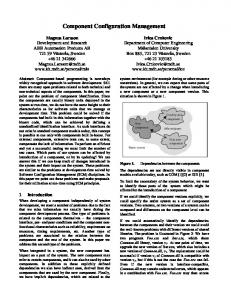
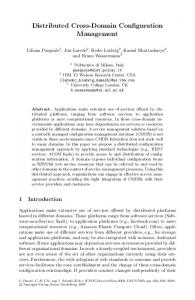


![Git & Mercurial: Distributed Configuration Management [PDF]](https://m.moam.info/img/260x300/git-mercurial-distributed-configuration-management_64b77fda098a9e71538b4576.jpg)


