JUNE 2010
VOLUME 57
NUMBER 6
IEBEAX
(ISSN 0018-9294)
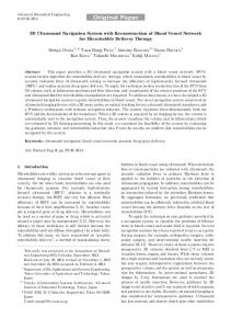
Configuration of IV image overlay navigation system. (See “3-D Augmented Reality for MRI-Guided Surgery Using Integral Videography Autostereoscopic Image Overlay” by Liao et al., p. 1477.)
1476
IEEE TRANSACTIONS ON BIOMEDICAL ENGINEERING, VOL. 57, NO. 6, JUNE 2010
3-D Augmented Reality for MRI-Guided Surgery Using Integral Videography Autostereoscopic Image Overlay Hongen Liao∗ , Member, IEEE, Takashi Inomata, Ichiro Sakuma, Member, IEEE, and Takeyoshi Dohi
Abstract—A 3-D augmented reality navigation system using autostereoscopic images was developed for MRI-guided surgery. The 3-D images are created by employing an animated autostereoscopic image, integral videography (IV), which provides geometrically accurate 3-D spatial images and reproduces motion parallax without using any supplementary eyeglasses or tracking devices. The spatially projected 3-D images are superimposed onto the surgical area and viewed via a half-slivered mirror. A fast and accurate spatial image registration method was developed for intraoperative IV image-guided therapy. Preliminary experiments showed that the total system error in patient-to-image registration was 0.90 ± 0.21 mm, and the procedure time for guiding a needle toward a target was shortened by 75%. An animal experiment was also conducted to evaluate the performance of the system. The feasibility studies showed that augmented reality of the image overlay system could increase the surgical instrument placement accuracy and reduce the procedure time as a result of intuitive 3-D viewing. Index Terms—Image overlay, integral photography (IP), integral videography (IV), registration, surgical navigation, threedimensional image.
I. INTRODUCTION RI IS a medical imaging technique commonly used in radiology to visualize the structure and function of the body. MRI provides much greater contrast between the different soft tissues of the body than computed tomography (CT) does, making it especially useful for neurological, cardiovascular, and oncological imaging. The obtained images are used to accurately identify treatment areas by acquiring pre-/intraoperative information and updating it to a navigation system used in
M
Manuscript received February 3, 2009; revised June 22, 2009 and November 9, 2009; accepted January 1, 2010. Date of publication February 17, 2010; date of current version May 14, 2010. This work was supported in part by Grant for Industrial Technology Research (07C46050) of New Energy and Industrial Technology Development Organization, Japan, by the Communications R&D Promotion Programme under Grant 062103006 of the Ministry of Internal Affairs and Communications in Japan, by the Special Coordination Funds for Promoting Science and Technology commissioned by the Ministry of Education, Culture, Sports, Science and Technology in Japan, and by Secom Science and Technology Foundation. This paper was presented in part at the Third International Workshop on Medical Imaging and Augmented Reality, Shanghai, China, August 2006. Asterisk indicates corresponding author. ∗ H. Liao is with the Department of Bioengineering, Graduate School of Engineering, and Translational Systems Biology and Medicine Initiative, University of Tokyo, Tokyo 113-8656, Japan (e-mail:
[email protected]). T. Inomata and T. Dohi are with the Department of Mechano-Informatics, Graduate School of Information Science and Technology, University of Tokyo, Tokyo 113-8656, Japan. I. Sakuma is with the Department of Precision Engineering, Graduate School of Engineering, University of Tokyo, Tokyo 113-8656, Japan. Color versions of one or more of the figures in this paper are available online at http://ieeexplore.ieee.org. Digital Object Identifier 10.1109/TBME.2010.2040278
MRI-guided therapy. Numerous studies have demonstrated the potential efficacy of open MRI-guided tumor extraction and therapy [1]–[3]. For total resection of the tumor in neurosurgery or puncturing a target in abdominal surgery, intraoperative imaging has been used to monitor the extent of tumors/targets and increase their success rate in surgery. The objective of this imageguided surgery is to enhance the surgeon’s capability of utilizing medical imagery in order to decrease the invasiveness of surgical procedures and increase their accuracy and safety. However, the display used for the surgical navigation systems is often situated away from the surgical field. This setup forces the surgeon to take extra steps to match guidance information on the display with the actual anatomy of the patient. This hand–eye coordination problem has been discussed as a possible cause of the interruption of surgical flow [4]. Furthermore, most of the medical information in pre-/intraoperative images provided to surgeons is displayed as a set of 2-D sectional images displayed away from the surgical area. The surgeon had to reconstruct 3-D information in their mind. However, the reconstructed information sometimes differs between individual surgeons. The use of a head-mounted display (HMD) in image-guided surgery augments the surgeon’s view of the surgical field with computer-generated images [5], [6]. A typical HMD has either one or two small displays with lenses and semitransparent mirrors embedded in a helmet, eyeglasses, or visor. HMD-type image-guided navigation systems have been used in various forms to assist surgeons by supporting and improving visualization of the surgical area [7]. With additional improvements to display resolution, structures, and the designs that merge both the real world and registered synthetic imagery have significantly increased the benefits of such systems to medical use. However, these systems still suffer the problem of a lag for motion parallax and cannot provide a natural view for multiple observers. The use of a half-silvered mirror for merging computergenerated images with a direct view enables an image overlay that displays image slices in situ [8], [9]. Blackwell et al. developed a binocular stereoscopic image-based overlay system [10]. Using this image overlay with reconstructed 3-D medical images, a surgeon can see through the patient’s body while being exactly positioned within the patient’s anatomy. This system potentially enhances the surgeon’s ability to perform a complex procedure. Although current augmented reality systems can adequately handle depth cues based on geometry (for instance, relative size, motion parallax, and stereo disparity), incorrect visualization of
0018-9294/$26.00 © 2010 IEEE
LIAO et al.: 3-D AUGMENTED REALITY FOR MRI-GUIDED SURGERY USING IV AUTOSTEREOSCOPIC IMAGE OVERLAY
Fig. 1.
1477
Configuration of IV image overlay navigation system.
interposition between real and virtual objects has already been identified as a serious issue [11], [12]. Furthermore, when real and virtual images are merged, relative position and information in terms of depth may not be perceived correctly, even though all positions are computed correctly. How to provide an ideal environment for using augmented reality in image-guided surgery is also discussed by Lerotic et al. [13] and Navab et al. [14]. In response to the aforedescribed issues, we have developed an autostereoscopic imaging technique, in contrast to a 2-D display or binocular stereoscopic display [15], which can be integrated into a surgical navigation system by superimposing an actual 3-D image onto the patient. The autostereoscopic images are created by using a modified version of integral videography (IV) [16], [17], which reproduces 3-D images using a microconvex lens array and a high-resolution high-pixel-density flat display. In IV, a fast image-rendering algorithm is used to project a computer-generated graphical object through a microconvex lens array. Each point shown in a 3-D space is reconstructed at the same position as the actual object by the convergence of rays from the pixels of the elemental images on a computer display after the rays pass through lenslets in the lens array. The surgeon can see any point on the display from various directions, as if it were fixed in 3-D space. Each point appears as a different light source, and a 3-D object is thus constructed as an assembly of reconstructed light sources. The depth of the IV image can be perceived easily by the observer intuitively and objectively, a key difference compared to the technique using binocular stereoscopic image. Switching to “scene mode” enables IV to display animated objects. The developed IV technique provides geometrically accurate 3-D images and reproduces motion parallax without using any supplementary eyeglasses or tracking devices. In this study, we developed an IV image overlay navigation system incorporating a fast and semiautomatic tumor segmentation method for open MRI-guided surgery. We also developed IV image calibration and markers-based registration method
for patient-to-image registration in an IV image overlay system. We evaluated the feasibility of the developed navigation system by using two sets of phantom experiment and an animal experiment. With additional improvements in the display, these systems should improve the surgical accuracy and reduce invasiveness. II. MATERIALS AND METHODS A. Configuration of IV Image Overlay Navigation System The system concept for the 3-D augmented reality navigation consists of an IV overlay device, a 3-D data scanner, a position tracking device, and two computers for image rendering and display (as shown in Fig. 1). The IV overlay device is combined with an IV display aligned with a half-silvered mirror; the device is mounted on a robotic arm that can manipulate the overlay device to the required position and posture. The spatially projected 3-D images are superimposed onto the patient and appear via a half-silvered mirror. The system includes two software clusters. One is for navigation software relative to basic navigation. The other software cluster is for IV image overlay. In this paper, the navigation information of the segmented data and the intraoperative spatial coordinate transformation matrix is transmitted by transmission control protocol (TCP)/IP network to the image overlay device. The resulting IV images are displayed on the IV image overlay device. A fuzzy connectedness (FC) algorithm was used to perform intraoperative tumor segmentation [18]. The algorithm automatically computes a fuzzy scene in the form of regional 3-D tissue images. The segmentation method was combined with 3D Slicer [19]. The 3D Slicer includes a GUI and a 2-D/3-D viewer, which uniquely integrates several aspects of image-guided medicine into a single environment. The user interface of the IV image overlay navigation system was developed as an extended module based on 3D Slicer. The approach
1478
Fig. 2.
IEEE TRANSACTIONS ON BIOMEDICAL ENGINEERING, VOL. 57, NO. 6, JUNE 2010
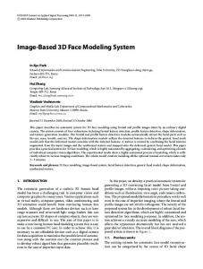
IV image overlay device.
taken for maximizing rendering speed is to use a single instruction multiple data stream (SIMD)—architecture computing combined with a volume-rendering algorithm [20]. B. IV Image Display and Overlay Device The IV display is coupled with a half-silvered mirror, and the overlay device is covered by a light-shield frame with a viewing window (see Fig. 2). The half-silvered mirror reflects an autostereoscopic image on the IV display back to the surgeon. Looking through this mirror, the surgeon sees the IV image formed in the corresponding location in the body. The distance between the half-silvered mirror and the IV display is about 30 cm, which is the same as that between the mirror and the patient. This distance allows the surgeon to freely manipulate a surgical instrument in the required operation space. The space can be extended to more than 50 cm by changing the distance between the mirror and the IV display. The size of the viewing window in the shield frame is determined by the corresponding viewing angle of the IV display. This design limits the viewing angle and prevents observation of a flitter image from the adjacent lens. The spatially projected 3-D images are superimposed onto the patient via the half-silvered mirror. One of the advantages of this overlay device is that the surgeon is intuitively guided during the surgical intervention without having to divert attention away from the surgical field. Furthermore, optical markers are mounted on the overlay device to track its position and orientation. The device can thus be pushed away from the surgical area when not needed and pulled back into the surgeon’s field of view when required during an operation. The IV images can be updated automatically according to the position and orientation of the overlay device. C. Registration of Spatial 3-D Image in Patient The error between the lens pitch and the width of the elemental image (corresponding to each lens) causes the deformation of the IV image, which may significantly affect the perceived
Fig. 3. IV image overlay device with IV image and reflected spatial image. When the surgeon sees through the viewing window, he sees the IV image as if it is fixed in 3-D space. (b) Using an optical probe to calibrate the spatial position of reflected IV images located in different planes. Calibration can be used to derive the translation matrix between the projected images and the optical markers. (c) Calibration of the position of the reflected spatial IV image.
depth perception of deep locations. Accordingly, pixel adjustment and image correction must be performed before the IV display is used. We used a set of spatial test patterns to calibrate the displayed IV image. The focal length of the lens array and the size of elemental images can be thus adjusted according to the calibration results. The fiducial markers used in image registration provide pairs of corresponding 3-D points in the spaces to be registered. A set of anatomic or fiducial markers (more than four markers located in different planes) is used to track the position of the patient’s body. The same markers can be detected by MRI and localized in the position sensor space by computing their 3-D coordinates. Once all displayed objects have been transformed into the same coordinate space using these transformations, they will appear to the surgeon exactly as if they were in their virtual spatial locations. This procedure enables theoretical registration of the reflected spatial 3-D image in conjunction with the target object. The registration process consists of the following steps. The process for representing the relationship between the IV display and the coordinates of the reflected spatial IV image consists of the following three steps (see Fig. 3).
LIAO et al.: 3-D AUGMENTED REALITY FOR MRI-GUIDED SURGERY USING IV AUTOSTEREOSCOPIC IMAGE OVERLAY
Fig. 4.
1479
Superimposition of spatial 3-D image in patient.
1) Project an IV image of a spatial calibration model with special calibration points and reflect the image into 3-D space via the half-slivered mirror [see Fig. 3(a)]. The model makes it possible to determine a geometric transformation that links the two coordinate spaces. 2) Calibrate the rigid body of the optical markers, Mar, attached to the IV image overlay device, relative to the opar tical tracking system, Tra, by M Tra T . Get the positions of the device and the displayed IV images of the calibration model. 3) Mark the special calibration points in the reflected spatial IV image with a 3-D position tracking probe to indicate their position with respect to the physical space around the points [see Fig. 3(b)]. Determine the transformation relationship between the reflected IV images and the optiar cal markers attached to the IV image overlay device M Im g T [see Fig. 3(c)]. The transformation matrix T (p) = Rp + t, where R is a 3 × 3 rotation matrix, t is a 3 × 1 translation vector, and p is a 3 × 1 position vector, can be found from two 3-D point sets {pi } and {qi } (i = 1, 2, . . . , N ) using the least squares fitting solution of Arun et al. [21]. ar With the transformation M Im g T , we can obtain the spatial positions of the reflected IV images simply by tracking the optical markers attached to the IV image overlay device. Furthermore, since the optical markers are fixed to the IV image overlay dear vice, given by M Dis T , we can also obtain the relationship between the IV overlay device and the reflected spatial IV image, Dis Im g T , ar Dis M ar from M T = T T . Im g Im g Dis As for patient–image registration, an optical tracking probe is used to track the fiducial markers and identify the position of the patient’s body. The relationship between the reflected spatial IV image and the patient can be determined in the following step (see Fig. 4.). 4) Mark fiducial markers M with an optical tracking probe to indicate their position with respect to the physical space of the patient, Pat, producing transformation Pat Tra T . The transformation from the coordinate of the reflected IV image, Img, to the coordinate of the patient is therefore M ar Tra Pat given by Pat Im g T = Im g T M ar T Tra T .
Fig. 5.
Software alignment for surgical navigation and IV image overlay.
The spatial position of the IV image is calculated by using the transformation matrix obtained before. The IV image can be thus assigned to the patient automatically. As for surgical tools, another set of optical position markers is attached to the tool, and the position and orientation of the tool are tracked. The IV image of the surgical tool is obtained in the following step. 5) Track the rigid body motion of the marker (and therefore of the intraoperative surgical tool) relative to the optical tracking system, producing transformation Sur Tra T . The IV image of the surgical tool is therefore given by Sur Im g T = M ar Tra Sur T T T in real time. Im g M ar Tra D. Software Alignment for Surgical Navigation and IV Image Overlay The IV image overlay navigation system includes two software parts (see Fig. 5). One is for navigation software relative to basic navigation, including navigation tools, intraoperative segmentation of target objects, point-based patient-to-image registration, and control of the optical localizer. The MR images are transferred from the scanner in Digital Imaging and Communications in Medicine (DICOM) data format. The navigation information composed of segmented data and an intraoperative spatial coordinate transformation matrix that is transmitted by a TCP/IP network to the image overlay device.The other is responsible for creating the IV overlay that is semiautomatically registered to the patient, as described in Section II-C, and incorporates high-speed IV image rendering and display of the tumor,
1480
IEEE TRANSACTIONS ON BIOMEDICAL ENGINEERING, VOL. 57, NO. 6, JUNE 2010
critical regions, and surgical tools. The resulting IV images are transferred to the PC and displayed on the IV image overlay device via a 1000-Mb/s-based Ethernet. E. Surgical Procedure of MRI-Guided Surgery Using IV Image Overlay To ensure safety and reliability of surgical treatment, the IV image calibration and the image overlay system must be verified before each is implemented. The surgical procedure workflow for MRI-guided surgical implementation is as follows. 1) Preoperatively calibrate the spatial position of the reflected IV image by using the method described in Section II-C. 2) Place sterile fiducial markers on the surface of the patient’s body and scan the target area by open MRI to obtain the patient’s image data. 3) Transfer the MR image in DICOM format to the IV rendering software implemented on a high-performance computer. 4) Segment the target of interest and markers from the MRI data. Perform intraoperative segmentation and patient-toimage registration. 5) Render the IV images and transfer them to the overlay device. Install the IV overlay device and superimpose the reflected spatial IV image onto the patient. 6) Update the IV image according to the registration results and verify the alignment of the overlay image on the patient. 7) Perform the surgical treatment under the guidance of IV image overlay. The surgeon moves the surgical instrument toward the IV target image behind the mirror and adjusts the position and orientation of the instrument. 8) After finishing the treatment, translate the patient into the scanner again and confirm whether the entire tumor was resected or the target was punctured. Surgical treatment continues until successful surgical implementation is confirmed by MR image. The aforementioned procedure should be repeated if the surgical task is not completed. Because the IV display device is tracked intraoperatively by the optical tracking device, it can be moved out of the surgical area intraoperatively when not needed. III. EXPERIMENT AND RESULTS A. Accuracy Measurement of IV Image Overlay We first conducted one set of experiment to assess the accuracy of the registration of the IV image overlay by using markers in a phantom. The phantom consisted of a plastic container simulating the human head. We embedded five markers for registration and two for error measurement [see Fig. 6(a)]. The five markers were used to register the IV image within the physical space of the phantom at different image depths. The two donut markers, both 10 mm in external diameter and 3 mm in internal diameter, were used as the targets. The markers were easily identifiable with MRI. The mean lateral spatial resolution of 30 measurements within an area of 30 mm away from the lens plane was 1.2 mm. The MR image data for the phantom
Fig. 6. Experimental measurements of accuracy of IV overlay. (a) Head model attached with five markers for registration and two markers for evaluation. (b) IVs overlaid on the markers.
Fig. 7. Results of the accuracy experiment. Overlay error changes according to the distance from the IV display.
consisted of one set of coronal images with a 0.90 × 0.90-mm in-plane resolution and a 1.5-mm slice gap (T2 axis imaging; TR: 1000 ms; TE: 140 ms; Matrix: 256 × 256; slices: 100; field of view (FOV): 230 mm × 230 mm; slice thickness: 1.0 mm; slice gap: 1.5 mm). The accuracy of IV image registration was evaluated, and the target registration error (TRE) was measured by using the phantom of human head. After the positions of the five markers for registration were obtained, the IV images were overlaid on the donut markers automatically by using the semiautomatic registration method described in Section II-C [see Fig. 6(b)]. The distance between the center of the actual donut marker and that of the spatial projected IV donut marker was measured as an overlay error. Four different operators used the optical tracking device to measure the position of the markers in the IV image, and repeated the measurements ten times for each distance. The mean value of the difference between the measured and physical coordinates of the two markers was 0.90 mm, and the standard deviation was 0.21 mm (see Fig. 7). The maximum error of 1.32 mm was better than that we expected because the slice gap was 1.5 mm. Our IV autostereoscopic image overlay with markers placed in different planes in the space enabled a high spatial registration. Actually, the registration accuracy of about 1 mm was better than expected. There are two reasons to explain this result. One is that we used autostereoscopic IV images, which include the image depth of the observed object. Although the slice gap is 1.5 mm, the reconstructed 3-D spatial image of the IV images
LIAO et al.: 3-D AUGMENTED REALITY FOR MRI-GUIDED SURGERY USING IV AUTOSTEREOSCOPIC IMAGE OVERLAY
1481
Fig. 8. (a) Phantom for feasibility evaluation. (b) MR images of the agar phantom with acrylic cylinder targets. (c) and (d) Screenshots of 2-D display-based navigation. When using only the 2-D display navigation system, operators needed to change the direction for viewing a target because of a lack of depth perception.
with markers placed in different planes in the space enabled high-accuracy 3-D space registration. The other reason is that we used five markers (surrounding the surface of the model) for registration and two markers (inside the five registration markers) for error measurement. After this, we adjusted the IV image overlay device and overlaid the IV images of five markers on a phantom of a human head. B. Targeting Experiment Using IV Image Overlay Guidance and 2-D Image Guidance We compared the procedure time and success rate of targeting an object. Azar et al. analyzed user performance by means of a different visualization system [22]. Our experiment focused on targeting objects using 2-D image guidance and IV overlay system guidance. The phantom consisted of a plastic cube container (150 mm ×150 mm × 100 mm) filed with an agar. Six MRI markers were attached on the phantom along its circumference. Three sets of acrylic cylinders with diameters of 1.5, 2, and 3 mm were embedded within the phantom [see Fig. 8(a)] to simulate the lesions that were easily identified as imaging targets [see Fig. 8(b)]. The centers of donut markers were targeted. In approaching the target under 2-D image guidance, the operator needed to change the view direction [e.g., from Fig. 8(c) and (d)] because of the lack of the depth perception of image. While Fig. 9 shows a target IVs overlaid to the agar phantom when the operators approach to the tip of the acrylic cylinder targets with the surgical needle. This method enables a smooth procedure of approaching a target compared with the 2-D image guidance. Tables I and II list the results of the “approach” experiment using 2-D image guidance and IV image overlay by four operators for each of ten trials. We removed the agar and determined, via the needle tracks in the medium, whether or not the needle had intersected each target. The IV image overlay improved the success rate by 33.3% and 26.7% for cylinder diameters of 1.5 and 2 mm, respectively, compared with using 2-D navigation guidance. Because of the individual difference in operator skills, operator B failed to target the smallest acrylic cylinder with diameter of 1.5 mm. The test results show that different operators could have individual differences in regard to their ability to target images/objects during the tests. Fig. 10 plots procedure time against diameter of target for both systems. The
procedure time dropped to 6 s on average, which is only 24.9% of that of the 2-D image navigation system. C. Feasibility Evaluation for Image-Guided Surgery We evaluated the feasibility of the developed system by a volunteer test. In the feasibility tests, we performed MRI to scan the brain. The volumetric T2-weighted MR images of the brain (TR: 1000 ms; TE: 140 ms; NEX: 1; resolution: 256 × 256 pixels×94 slices: thickness: 1.0 mm) were segmented, and the rendered IV images were transferred to the IV display. Fig. 10 shows an overlaid IV image of the brain on a volunteer’s head. The images could be viewed from different directions, and motion parallax could be generated as if it were fixed in the body. Motion parallax is a depth cue that results from the motion of an observer. As a person moves, objects that are closer to them move farther across their field of view (FOV) than objects that are in the distance do. This relative motion of the visual image on the retinas, known as motion parallax, is used by the visual system to generate a sensation of depth [23]. The motion parallax of IV autostereoscopic brain images combined with the volunteer’s head was taken from various directions (see Fig. 11). Fig. 12 shows an image of the surgical instrument, brain tumor, and ventricle directly overlaid on a human model. The IV image of the surgical instrument inserted into the model was displayed and updated according to the change of its position and orientation. A real-time IV algorithm developed for calculating the 3-D image of surgical instruments enabled an image update of over 10 frames/s. D. In Vivo Animal Experiment We also evaluated the feasibility of the system by an animal experiment that involves targeting a pig’s gallbladder. A set of markers (TH-N7510, CHIYODA TECHNOL CORPORATION, Japan) was attached to the skin of the surgical area. To demonstrate the ability of 3-D space guidance, the surgical instrument for targeting a required organ was performed with the IV image overlaid on a pig. The overlay device placed over the surgical area was covered with a sterile cover [see Fig. 13(a)]. The viewing window and the half-silvered mirror were covered by acrylic sheets, so that both the IV image and the pig’s body could be viewed [see Fig. 13(b)]. The surgical area was scanned
1482
IEEE TRANSACTIONS ON BIOMEDICAL ENGINEERING, VOL. 57, NO. 6, JUNE 2010
Fig. 9. Target IVs overlaid on as agar phantom. Operators approached to the tip of the acrylic cylinder targets with a surgical probe.
Fig. 10. Procedure time versus diameter of targets for 2-D image guidance and IV image overlay.
TABLE I RESULTS OF SURGICAL TOOL APPROACH EXPERIMENT WITH 2-D IMAGE GUIDANCE
TABLE II RESULTS OF SURGICAL TOOL APPROACH EXPERIMENT WITH IV IMAGE OVERLAY NAVIGATION
Fig. 11. Registration of IV image and volunteer’s head. Motion parallax of IV autostereoscopic brain images combined with the volunteer’s head is taken from various directions. The letters denote the relative position of the observer.
by an MR device (Hitachi, AIRIS II, Japan). The fiducial markers and target area were then extracted from the MR images [see Fig. 13(b)]. Using image overlay to display the 3-D location of fiducial markers, target, and critical areas, the surgeon plans the approach to minimize the surgical exposure. An optical tracking device was used to measure the spatial location of the surgical instrument by tracking a probe fixed to the instrument (StarBurstTM MRI, Electrosurgical Device, RITA Medical Systems, Inc., USA), as shown in Fig. 14. The position data were used to create an intraoperative IV image of the instrument. The targeting experiment was performed by a medical doctor. After the targeting test was finished, the surgical area was scanned again to confirm that the instrument had targeted the gallbladder (see Fig. 15). Although the markers attached to the skin affected the accuracy of registration, the postoperative checkup showed that the instrument successfully reached the target gallbladder.
The experiment was a test trail for accessing a gallbladder without using an extra invasive device like laparoscope. With the guidance of the noninvasive image overlay system, the surgeon can target the organ directly. However, note that further research work on deformation and movement of soft tissue need to be done before clinical implementation of this system. The result shows that the developed intraoperative IV image overlay technique with corresponding image registration can improve surgical navigation by providing a direct and intuitive view of the operation field. In combination with robotics, it can even supply guidance by predefining the path of a needle or by preventing the surgical instruments from moving into critical regions. IV. DISCUSSION We demonstrated a unique autostereoscopic image overlay technique for surgical navigation. An actual 3-D image is superimposed onto the patient by using a semitransparent display based on an adaptation of integral videography to image
LIAO et al.: 3-D AUGMENTED REALITY FOR MRI-GUIDED SURGERY USING IV AUTOSTEREOSCOPIC IMAGE OVERLAY
1483
Fig. 12. IV images overlay of tumor, ventricle, and surgical tool onto the phantom of the human brain. The photographs show different steps of insertion of a simulated surgical instrument.
Fig. 14. Optical tracking device for measuring spatial location of a surgical instrument.
Fig. 15. Targeting the gallbladder by using guidance of IV images overlay. The IV images of the markers and the target are overlaid to the body.
Fig. 13. Animal experiment: (a) experiment scene and (b) MR image slices with or without visible markers.
overlay. Two major experimental findings demonstrated the feasibility of the proposed technique. The registration accuracy for a rigid object was about 1 mm on average. With further work on deformation and movement of soft tissue, we believe the system will be useful for image-guided surgery. Our IV image overlay system has the following significant features compared to traditional techniques. First, autostereoscopic images can be observed without special glasses for 3-D vision or a tracking device to track the surgeon’s head. Second,
the patient, IV image, and surgical instrument are displayed in a single window. Third, the overlaid image provides an intuitive augmented reality environment that can be shared by multiple observers. Fourth, the spatial formation 3-D image provides visibility of motion parallax over a wide area. Fifth, geometrically accurate IV images are overlaid on the patient to enable the surgeon to see through the patient’s body. Phantom experiments showed that the overlay system enables higher accurate registration than a single-slice-based image overlay. This is because the IV images can be spatially registered on the object and viewed from different directions without distortion. The surgical instrument can be inserted from the required direction without changing the viewing angle of the
1484
overlay images, since the entire target can be directly viewed as if it were fixed inside the patient’s body. In this study, we only evaluated the system error of image overlay. Actually, the error sources include the error in the IV image, error in the spatial IV image calibration, and error in the patient-to-image registration. The error in the IV image (caused by mismatching of the lens pitch and focusing of the pixels on the displayed elemental images on the screen) could be corrected before use. The calibration of the spatially projected IV image should be done before each trail, since the setup of the half-silvered mirror and the IV display causes potential misalignment. The error of the patient-to-image registration is a significant issue, especially in regards to tissues or organs. Accordingly, corresponding appropriate automatic compensation and correction for the movement and deformation of the target should be considered in regards to system improvement. The correct alignment is independent of the viewpoint of the observer. The augmented reality windows with motion parallax of the IV image involve no lag when the viewer is moving. Furthermore, our method for IV image calibration enables the image to be registered to the patient without considering the parallax error from the mirror [9]. In this paper, we mentioned a key difference between the images created by IV and those created by other 3-D imaging techniques (e.g., binocular stereoscope), i.e., the IV image is a real 3-D image. Although the image reflected through a halfsilvered mirror and viewed by the observer is a virtual one, our image-overlay system is different from that using binocular stereoscopic image-based augmented reality, such as optical and video see-through HMD [24], because it merges a real 3-D image (the IV image) into a real object (the patient). The reflected spatial IV image is fixed at the required position although the IV screen cannot be placed at the position of the projected images (i.e., inside the patient’s body). This means that the position of the reflected IV image will not be changed even if the observer moves their eyes (i.e., viewpoints). Moreover, the IV image can provide depth perception and allow multiple viewers to have different perspectives from different directions. Geometrical accuracy (accuracy of the stereo cues) is important because it provides the observer with a 3-D image with precision spatial information. On the other hand, augmented reality created by using binocular stereoscope vision will cause individual differences, which will not have the same perceived image depth for individual observers. Although some techniques were designed to overcome misleading depth perception cues during the processing the video image of the patient’s surface to provide a transparent window or creating an image that emphasizes sparse features on the surface, they focused on the psychophysics of the human visual system with binocular vision. Of course, if the observer views an object through the viewing windows of the IV overlay device from a single viewpoint (by one eye without head motion), the viewing result will be the same as that of the system that overlays a video image onto the patient’s surface, because in that case, the eye is similar to a camera lens. However, the movement of the observation viewpoint or multiple viewpoints that form depth perception makes the difference
IEEE TRANSACTIONS ON BIOMEDICAL ENGINEERING, VOL. 57, NO. 6, JUNE 2010
between the IV autostereoscopic image overlay system and other AR systems, because such movement is the natural way that the human eyes view objects. Although the IV image overlay system is free from the issues regarding object positioning and depth cues that arise in case of augmented reality system [25], [26], one issue concerning IV image overlay that should be addressed is how to make the fusion of the IV image and the patient easy to observe (a task that includes adjustment of background light, reflection of the skin, etc.). Although updating the IV image of an anatomical object remains computationally costly in this study, advances in computer and graphic board hardware technology should obviate this problem. We have also built a graphics processing unit (GPU) based high-speed IV image generation system and a GUI interface through which interaction with an IV image (like rotating, scaling, and focusing) can be done smoothly [27], [28]. It will then be possible to register an anatomical object’s intraoperative configuration with the surgical instrument in real time by using intraoperative data gathered from a real-time image scanner or calculated from a deformation model [29]. In this study, the patient received an MRI scan, after which the patient was moved out of the gantry. The image overlay was performed out of the 5 G line. The patient must be translated in and out between the imaging and intervention. Since the patient is secured to the table and the table is translated with a linear drive mechanism, target offset due to table translation remains safely within the error margin of these procedures. Our future works will include evaluating the compatibility of the IV overlay device with the MR system. Moreover, we will develop an MR-compatible high-pixel-density liquid crystal display (LCD) screen. With the acquisition of intraoperative patient’s information, the problem of organ deformation and identification of the surgical instrument can be improved. V. SUMMARY Two phantom tests have shown that the IV image overlay produces an intuitive vision that allows the user to see through a patient’s body and perform accurate surgical treatment. Though the animal trials only tested a large target, namely, a pig’s gallbladder, the in vivo implementation of IV image overlay enables an intuitive visualization of most real environments of surgical fields. Experiments have shown that our 3-D surgical navigation system can superimpose a real and intuitive 3-D image onto a patient’s body for accurate and less-invasive surgery. The realtime IV algorithm developed for calculating the 3-D image of surgical instruments was effective in representing the real-time location of both surgical tools and targets during an operation. Because of the simplicity and accuracy of real-time-projected point location by means of a display device with higher pixel density, this system should be of practical use in neurosurgery and other medical fields. In conclusion, we developed an autostereoscopic image overlay system for MRI-guided surgery. A feasibility study indicated that the procedure of surgery and the proposed registration method could increase the accuracy of tumor resection or
LIAO et al.: 3-D AUGMENTED REALITY FOR MRI-GUIDED SURGERY USING IV AUTOSTEREOSCOPIC IMAGE OVERLAY
biopsy using a needle. The developed IV image overlay device with proposed method can be used in surgical navigation, which enables a safe, easy, and accurate surgical diagnosis and therapy. ACKNOWLEDGMENT The authors are grateful to Dr. Muragaki and Dr. Iseki in Tokyo Women’s Medical University Hospital and members of Dr. Hashizume’s group at the Center for Integration of Advanced Medicine, Life Science and Innovative Technology, Kyusyu University Hospital, for their technical and clinical assistance. REFERENCES [1] J. P. Schneider, T. Schulza, F. Schmidta, J. Dietricha, S. Lieberenza, C. Trantakisa, V. Seiferta, S. Kellermanna, R. Schobera, L. Schaffranietza, M. Laufera, and T. Kahna, “Gross-total surgery of supratentorial low-grade gliomas under intraoperative MR guidance,” AJNR Amer. J. Neuroradiol., vol. 22, pp. 89–98, 2001. [2] P. M. Black, T. Moriarty, E. Alexander, P. Stieg, E. J. Woodard, P. L. Gleason, C. H. Martin, R. Kikinis, R. B. Schwartz, and F. A. Jolesz, “Development and implementation of intraoperative magnetic resonance imaging and its neurosurgical applications,” Neurosurgery, vol. 41, pp. 831–842, 1997. [3] L. S. Lewin, C. F. Connell, J. L. Duerk, Y. C. Chung, M. E. Clampitt, J. Spisak, G. S. Gazelle, and J. R. Haaga, “Interactive MRI-guided radiofrequency interstitial thermal ablation of abdominal tumors: Clinical trial for evaluation of safety and feasibility,” J. Magn. Reson. Imag., vol. 8, no. 1, pp. 40–47, 1998. [4] P. Breedveld, H. G. Stassen, D. W. Meijer, and L. P. S. Stassen, “Theoretical background and conceptual solution for depth perception and eye-hand coordination problems in laparoscopic surgery,” Minim. Invasive Ther., vol. 8, pp. 227–234, Aug. 1999. [5] I. Sutherland, “Ahead-mounted three dimensional display,” in Proc. Fall Joint Comput. Conf., 1968, pp. 757–764. [6] K. Keller, A. State, and H. Fuchs, “Head mounted displays for medical use,” J. Display Technol., vol. 4, no. 4, pp. 468–472, Dec. 2008. [7] W. Birkfellner, M. Figl, K. Huber, F. Watzinger, F. Wanschitz, J. Hummel, R. Hanel, W. Greimel, P. Homolka, R. Ewers, and H. Bergmann, “A head-mounted operating binocular for augmented reality visualization in medicine,” IEEE Trans. Med. Imag., vol. 21, no. 8, pp. 991–997, Aug. 2002. [8] G. D. Stetten and V. S. Chib, “Overlaying ultrasound images on direct vision,” Int. J. Ultrasound Med., vol. 20, pp. 235–240, 2001. [9] G. Fichtinger, A. Deguet, K. Masamune, E. Balogh, G. S. Fischer, H. Mathieu, R. H. Taylor, S. J. Zinreich, and L. M. Fayad, “Image overlay guidance for needle insertion in CT scanner,” IEEE Trans. Biomed. Eng., vol. 52, no. 8, pp. 1415–1424, Aug. 2005. [10] M. Blackwell, C. Nikou, A. M. Digioia, and T. Kanade, “An image overlay system for medical data visualization,” Med. Image Anal., vol. 4, pp. 67– 72, 2000. [11] M. Bajura, H. Fuchs, and R. Ohbuchi, “Merging virtual objects with the real world: Seeing ultrasound imagery within the patient,” Comput. Graph., vol. 26, no. 2, pp. 203–210, Jul. 1992. [12] L. G. Johnson, P. Edwards, and D. Hawkes, “Surface transparency makes stereo overlays unpredictable: The implications for augmented reality,” in Medicine Meets Virtual Reality (MMVR), vol. 94 (Studies in Health Int. Technol. and Inf.), J. D. Westwood, Ed. Amsterdam, The Netherlands: IOS Press, 2003, pp. 131–136. [13] M. Lerotic, A. J. Chung, G. Mylonas, and G. Z. Yang, “pq-space based non-photorealistic rendering for augmented reality,” in Proc. Med. Image Comput. Comput.-Assist. Interv. (MICCAI 2007), II, (Lecture Notes in Computer Science 4792), pp. 102–109. [14] T. Sielhorst, C. Bichlmeier, S. M. Heining, and N. Navab, “Depth perception—A major issue in medical AR: Evaluation study by twenty surgeons,” in Proc. Med. Image Comput. Comput.-Assist. Intervention (MICCAI 2006) (Lecture Notes in Computer Science 4190), pp. 364– 372. [15] H. Liao, N. Hata, S. Nakajima, M. Iwahara, I. Sakuma, and T. Dohi, “Surgical navigation by autostereoscopic image overlay of integral videography,” IEEE Trans. Inf. Technol. Biomed., vol. 8, no. 2, pp. 114–121, Jun. 2004.
1485
[16] H. Liao, M. Iwahara, N. Hata, and T. Dohi, “High-quality integral videography using a multi-projector,” Opt. Exp., vol. 12, no. 6, pp. 1067–1076, 2004. [17] H. Liao, D. Tamura, M. Iwahara, N. Hata, and T. Dohi, “High quality autostereoscopic surgical display of integral videography imaging,” in Proc. Med. Image Comput. Comput.-Assist. Intervention (MICCAI 2004) (Lecture Notes in Computer Science 3217), pp. 462–469. [18] T. Inomata, Y. Muragaki, H. Iseki, T. Dohi, and N. Hata, “Intraoperative segmentation of brain tumors for open MRI guided glioma surgery,” in Proc. CARS 2004, p. 1284. [19] [Online]. Available: http://www.slicer.org [20] M. Meissner, S. Grimm, W. Strasser, J. Packer, and D. Latimer, “Parallel volume rendering on a single-chip SIMD architecture,” in Proc. IEEE 2001 Symp. Parallel Large-Data Vis. Graph., pp. 107–157. [21] K. S. Arun, T. S. Huang, and S. D. Blostern, “Least-square fitting of two 3-D point sets,” IEEE Trans. Pattern Anal. Mach. Intell., vol. PAMI-9, no. 5, pp. 698–700, Sep. 1987. [22] F. S. Azar, N. Perrin, A. Khamene, S. Vogt, and F. Sauer, “User performance analysis of different image-based navigation systems for needle placement,” Proc. SPIE, vol. 5367, pp. 120–121, 2004. [23] J. J. Gibson, The Perception of the Visual World. New York: Houghton Mifflin, 1950. [24] J. P. Rolland and H. Fuchs, “Optical versus video see-through headmounted displays in medical visualization,” Presence, vol. 9, no. 3, pp. 287–309, 2000. [25] T. Sielhorst, M. Feuerstein, and N. Navab, “Advanced medical displays: A literature review of augmented reality,” IEEE/OSA J. Display. Technol., Spec. Issue Med. Display., vol. 4, no. 4, pp. 437–450, Dec. 2008. [26] D. Drascic and P. Milgram, “Perceptual issues in augmented reality,” Proc. SPIE, Stereoscopic Displays Virtual Real. Syst. III, vol. 2653, pp. 123–134, 1996. [27] N. Herlambang, H. Liao, K. Matsumiya, K. Masamune, and T. Dohi, “Interactive autotereoscopic medical image visualization system using GPU-accelerated integral videography direct volume rendering,” Int. J. Comp. Assist. Radiol. Surg., vol. 3, Supp. 1, pp. 110–111, 2008. [28] H. H. Tran, K. Matsumiya, K. Masamune, I. Sakuma, T. Dohi, and H. Liao, “Interactive 3-D navigation system for image-guided surgery,” Int. J. Virtual Real., vol. 8, no. 1, pp. 9–16, 2009. [29] H. Liao, M. Tsuzuki, T. Mochizuki, E. Kobayashi, T. Chiba, and I. Sakuma, “Fast image mapping of endoscopic image mosaics with threedimensional ultrasound image for intrauterine fetal surgery,” Minim. Invasive Ther. Allied Technol., vol. 18, no. 6, pp. 332–340, 2009. Hongen Liao (M’04) received the B.S. degree in mechanics and engineering sciences from Peking University, Beijing, China, in 1996, and the M.E. and Ph.D. degrees in precision machinery engineering from the University of Tokyo, Tokyo, Japan, in 2000 and 2003, respectively. He was a Research Fellow of Japan Society for the Promotion of Science. Since 2004, he has been a faculty member at the Graduate School of Engineering, University of Tokyo, where he is currently an Associate Professor in the Department of Bioengineering. He is the author and coauthor of more than 110 peer-reviewed articles published in journals and conference proceedings, as well as more than 190 abstracts and numerous invited lectures. His research interests include medical image, image-guided surgery, medical robotics, computer-assisted surgery, and fusion of these techniques for minimally invasive precision diagnosis and therapy. He has also been involved in long viewing distance autostereoscopic display and 3-D visualization. Dr. Liao was the recipient of a Government Award [Commendation for Science and Technology by the Minister of Education, Culture, Sports, Science and Technology (MEXT), Japan]. He was also the recipient of more than ten awards including OGINO Award (2007), ERICSSON Young Scientist Award (2006), the International Federation for Medical and Biological Engineering Young Investigators Awards (2006 and 2005), and various Best Paper Awards from different academic societies. His research is well funded by MEXT, the Ministry of Internal Affairs and Communications, the New Energy and Industrial Technology Development Organization, and Japan Society for the Promotion of Science in Japan. He is an Associate Editor of the IEEE Engineering in Medicine and Biology Society Conference, the Organization Chair of the Medical Imaging and Augmented Reality Conference 2008, the Program Chair of the Asian Conference on Computer-Aided Surgery, and the Tutorial Co-Chair of the Medical Image Computing and Computer Assisted Intervention Conference 2009.
1486
IEEE TRANSACTIONS ON BIOMEDICAL ENGINEERING, VOL. 57, NO. 6, JUNE 2010
Takashi Inomata received the B.S. and M.S. degrees in mechano-informatics from the University of Tokyo, Tokyo, Japan, in 2003 and 2005, respectively. He is currently with the Department of MechanoInformatics, Graduate School of Information Science and Technology, University of Tokyo. His research interests include 3-D image processing, medical imaging, and surgical navigation.
Ichiro Sakuma (A’88–M’08) received the B.S., M.S., and Ph.D. degrees in precision machinery engineering from the University of Tokyo, Tokyo, Japan, in 1982, 1984, and 1989, respectively. From 1985 to 1987, he was a Research Associate in the Department of Precision Machinery Engineering, Faculty of Engineering, University of Tokyo. From 1991 to 1999, he was an Associate Professor in the Department of Applied Electronic Engineering, Tokyo Denki University, Saitama, Japan. He was an Associate Professor and a Professor at the Institute of Environmental Studies, Graduate School of Frontier Sciences, University of Tokyo, from 1999 to 2001, and from 2001 to 2006, where he is currently a Professor in the Department of Precision Engineering, Graduate School of Engineering, University of Tokyo. His research interests include biomedical instrumentation, simulation of biomedical phenomena, computer-assisted intervention, and surgical robotics. Prof. Sakuma is a Board Member of the Medical Image Computing and Computer Assisted Intervention Society, Japan Society of Computer Aided Surgery, and the Japanese Society of Electro Cardiology. He was the Vice President of the Japanese Society for Medical and Biological Engineering from 2006 to 2007.
Takeyoshi Dohi received the B.S., M.S., and Ph.D. degrees in precision machinery engineering from the University of Tokyo, Tokyo, Japan, in 1972, 1974, and 1977, respectively. He was a Research Fellow in the Institute of Medical Science, University of Tokyo. In 1979, he joined Tokyo Denki University, Tokyo, Japan, as a Lecturer, where he became an Associate Professor in 1980. From 1981 to 1988, he was an Associate Professor in precision machinery engineering at the University of Tokyo, where he has been a Full Professor since 1988, and is currently a Professor of information science and technology in the Department of Mechano-Informatics, Graduate School of Information Science and Technology. His research interests include computer-aided surgery, rehabilitation robotics, artificial organs, and neuro-informatics. Dr. Dohi was the President of numerous domestic society and international professional societies including the International Society for Computer-Aided Surgery, the Japanese Society for Medical and Biological Engineering, and the Japan Society of Computer-Aided Surgery. He was a Board Member of the Medical Image Computing and Computer Assisted Intervention Society.