faults with far fewer backtracks and leaves the system as efficient as before in the absence of conflicts. We have incorporated these techniques into a commercial ...
Conflict Driven Techniques for Improving Deterministic Test Pattern Generation Chen Wang1 & Sudhakar M. Reddy1,2 Elec. & Comp. Eng. Department University of Iowa, Iowa City, IA
Irith Pomeranz3 School of Elec. & Comp. Eng. Purdue University, West Lafayette, IN
Abstract This work presents several new techniques for enhancing the performance of deterministic test pattern generation for VLSI circuits. The techniques introduced are called dynamic decision ordering, conflict driven recursive learning and conflict learning. An important feature shared by all these techniques is that they are triggered by the occurrence of a conflict in the generation of tests. Hence, they are not active all the time nor for all the faults. This feature allows the ATPG system that uses these techniques to resolve hard-to-resolve faults with far fewer backtracks and leaves the system as efficient as before in the absence of conflicts. We have incorporated these techniques into a commercial D-algorithm based ATPG tool. The experimental results on full scan versions of ITC’99 benchmark circuits demonstrate an improvement of the ATPG system both in the number of aborted faults and in test generation time.
1. Introduction The high product quality requirement for industrial designs whose size doubles approximately every eighteen months has made design-for-test and test generation that achieve high fault coverage a critical need. During the past several decades, a great amount of work has been done in the field of automatic test pattern generation (ATPG). After the Dalgorithm[1] was proposed in the 1960’s, other algorithms proposed for circuits described at the gate level include PODEM[3], FAN[5] and SOCRATES[7]. Several techniques to improve the efficiency of these procedures such as static and dynamic learning[7], dominators[6], single path propagation[14] and recursive learning[10] have greatly enhanced the ability of ATPG procedures to resolve faults in a circuit. By resolution of a fault we mean that the ATPG procedure finds a test for a fault or determines that a fault is untestable; in other words it does not abort on the fault. The recent paper [18] describes several new techniques to enhance ________________________ 1. Research supported in part by a grant from Mentor Graphics Corporation, Wilsonville, OR. 2. Research supported in part by NSF grant No. CCR0097905 and in part by SRC Grant No. 2001-TJ-949. 3. Research supported in part by NSF grant No. CCR0098091 and in part by SRC Grant No. 2001-TJ-950.
0-7803-7607-2/02/$17.00 ©2002 IEEE
Xijiang Lin & Janusz Rajski Mentor Graphics Corp. Wilsonville, OR
ATPG for gate level circuits. These techniques were implemented into a PODEM based ATPG system called ATOM[18]. ATPG for a circuit can also be viewed as solving a Boolean satisfiability (SAT) problem. Initial work for SAT based procedures was done in [11] and several SAT based test generation systems have been developed [15,16,17]. A recently developed SAT based ATPG system called SPIRIT[20] includes several new techniques to improve the efficiency of SAT based ATPG procedures. Since deterministic test pattern generation is known to be an NP-complete problem[4], efficient techniques to avoid the worst case exponential search are of practical importance. Some techniques such as x-path check[3], static learning[7], unique sensitization[5] and structural dominator[6] are found to be universally applicable and hence are used as default options in almost every ATPG system today. By universally applicable we mean that these techniques facilitate resolving any fault in any circuit without negative impact on test generation time. Other techniques such as dynamic learning[7] and recursive learning [10] are found to be fault specific or circuit specific in improving test generation efficiency. That is, for certain circuits or particular faults in a circuit, these techniques can help reduce the run time for resolving hard-toresolve faults, however, for some other cases these techniques will degrade the system performance. Since the overall performance obtained after incorporating such techniques is hard to predict, some ATPG systems use them as non-default options and only apply them to a small group of faults such as the aborted faults from a previous pass of the ATPG run. In this paper we propose several new techniques to improve test generation efficiency. The unique feature of all the proposed techniques is that they are automatically triggered only when they are deemed to be helpful to resolve the currently targeted fault. Thus these techniques can be run during all passes of an ATPG and they will become active when they are needed. Experimental results presented on benchmark circuits demonstrate the high effectiveness of these procedures. The paper is organized in the following way. In section 2 the baseline ATPG system which is enhanced by the proposed techniques is described. In section 3 we describe the new techniques proposed in this work. In section 4 we give experimental results. Section 5 includes conclusions.
2. Preliminaries The baseline ATPG we use is a state of the art ATPG based on the D-algorithm. It uses many of the known techniques mentioned above to enhance the ATPG efficiency. In D-algorithm based ATPG, decisions are made on internal lines in contrast to PODEM based algorithms in which decisions are made only on circuit inputs. As is well known, decisions made on internal lines are of two types. One is for fault effect propagation also known as D propagation using the D-calculus notation[1]. The other is to justify a value on a circuit line. We call these justification decisions. f
b=1 a1
g
d
e=D
out of the two choices for setting a=0, the decision to use a1=0 is indicated in the leftmost node of the second level of the decision tree by 1/2, which indicates that the first of the two choices to justify a=0 is taken. The order in which the justification problems corresponding to the nodes with the same parent are solved is important in reducing test generation time. For the sake of discussion in this work, we assume that this order is from left to right. For example, referring to Figure 1(b), the justification problem a=0 is considered before b=1 which is considered before c=1.
3. New Techniques In this section we describe the proposed new techniques to improve the efficiency of deterministic ATPG procedures.
b
a/1
a2
c=1
(a)
h a1
c e
TG a/1
f=1
a=0 d1
J a=0 /2
J b=1 /2
J c=1 /3
d
De /3
d2
(b)
j
a2
g=1
TG a/1
Figure 2. Example circuit J a=0 1/2
J f=0 /2
J b=1 /2
J c=1 /3
De /3
J g=0 /2
(c) Figure 1. Decision tree of D-algorithm
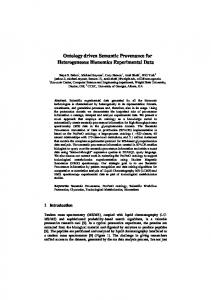
In order to describe the new techniques proposed in Section 3, we next illustrate the notation we use for decision trees commonly used in all ATPG procedures. Figure 1(a) shows part of a circuit together with a partial decision tree to generate a test for the fault line a stuck-at-1 (written as a/1). In the decision tree, nodes are labeled with the problems that need to be solved. For example the root node is labeled TG for test generation, the three leftmost nodes in the second level are for justifying line values a=0, b=1 and c=1 and hence carry a label J, and the rightmost node at this level is for propagating the fault effect or D from e. In each node, the number of choices that exist for achieving the corresponding objective is shown to the right of a slash. In Figure 1(c) we show the decision tree when the decision to set a1=0 in order to justify a=0 is made. Note that
3.1 Dynamic Decision Ordering A decision related to line justification is made when one among several choices for solving a justification problem is made or when one among several yet to be solved problems is chosen for solving. The order in which the available choices or problems to be solved are tried can be statically determined or dynamically determined. Typical static ordering techniques used are random order and orders based on controllability and observability measures[2,9]. Dynamic ordering techniques include updating controllability and observability measures when decisions at other circuit nodes are made while generating a test for a fault [8]. The technique proposed here called Dynamic Decision Ordering (DDO) dynamically changes the order of solving a set of justification problems at the same level of the decision tree. This is illustrated by the following example. Example 1: To illustrate the dynamic decision ordering technique, consider the circuit shown in Figure 2. A part of the decision tree to justify a=0 is shown in Figure 3. Figure 3(a) illustrates the new justification problems created due to the decision to set a=0 by justifying a1=0. In order to set a1=0, it is necessary to set h=0 and e=0. The requirement e=0 leads to entering three new justification problems b=0, c=0 and d=0 into the decision tree. Let the order in which these justification problems are solved be as shown in Figure 3(a) (from left to
To facilitate recognizing that a value on a line was found to be unjustifiable during the generation of a test for a given fault, we set a flag bit called R (reorder) associated with this line and value. We use it in ordering the sibling nodes of this line if it appears in the decision tree again with the same value. Rule 2: If the R flag corresponding to a node is set, place this node ahead of any sibling node whose R flag is not set. The R flag of a line and value is reset if the corresponding node justification problem is found to have a solution when it is processed again during the test generation process for the current target fault. An application of Rule 2 is illustrated in Figure 4. It is important to note that reordering of decision nodes as given by Rules 1 and 2 is done only when unsolvable justification problems are encountered in generating a test for a target fault. When the test is generated or the target fault is proved to be untestable or aborted, all the decision node orders are reset to the default order used in the original test generation procedure and the R flags of all the lines and values are reset. That is, the dynamic reordering is only temporary and it is valid only for the test being generated currently (for one or more target faults). It should be mentioned that an earlier proposed method called non-chronological backtracking [16] would reduce the number of backtracks more than the dynamic decision ordering proposed here. However, the cost of capturing and analysis of data required to achieve non-chronological backtracking is high and for this reason non-chronological backtracking is typically not used in ATPG.
right). Assume that we choose to solve b=0 and c=0 by taking the first of the two alternatives to solve each of these problems. This is indicated by 1/2 in the two leftmost nodes. Next we attempt to solve d=0 by setting d1=1 which leads to a conflict as indicated in Figure 3(a). This conflict leads to a backtrack and we try to solve d=0 by setting d2=1 which also leads to a conflict as shown in Figure 3(b). Typically the test generation procedure would undo the decisions made at nodes c=0 and d=0 of Figure 3(b) and try the second option to set c=0. It would then again process c=0 and d=0, and determine that again conflicts occur at d=0. After that, the second choice of b=0 will be tried and more conflicts will be met since d=0 is unsolvable. Thus the test generator determines that the requirement a1=0 is not achievable after considering decisions for solving b=0, c=0 and d=0 several times. It can be observed from Figure 2 that the reason for the non-existence of a solution to set a1=0 is that d cannot be set to 0. Thus, if we order the three sibling nodes (nodes with the same parent node) at level two in the decision tree as shown in Figure 3(c) when it is first detected that d=0 cannot be achieved, then the fact that a1=0 cannot be achieved will be determined by processing the line justification node d=0 of the decision tree twice, once to detect that d=0 cannot be achieved and once after reordering the nodes. It is important to note that when the sibling nodes in the decision tree are reordered, all previous decisions on these nodes are undone as shown in Figure 3(c). The motivation behind such reordering is that most of the time the conflicts occurring at sibling nodes of the decision tree are due to independent reasons and hence if a J a=0 1/2
J b=0 1/2
J c=0 1/2
J a=0 1/2
J d=0 1/2
J b=0 1/2
J c=0 1/2
Fail
J a=0 1/2
J d=0 2/2
J d=0 /2
J b=0 /2
J c=0 /2
Fail Start over here
(a)
(b)
(c)
Figure 3. Illustration of dynamic decision ordering Rule 1
justification problem cannot be solved then it is unsolvable independent of the decisions made for the sibling nodes. These observations lead to the following rule for dynamic decision ordering. Rule 1: In generating a test for a fault, if it is determined that a line justification problem cannot be solved, move the corresponding node to be the leftmost node among its siblings and undo all the decisions made on the siblings. In the example illustrated by Figure 2, another point can be observed that leads to Rule 2 for dynamic reordering of justification problems to be solved in the decision tree. After reordering using Rule 1 given above and determining that a1=0 cannot be achieved, we would next attempt to solve justification problem a=0 by setting a2=0. In this case we will again encounter the d=0 justification problem. It is preferable to first try to solve d=0 before trying j=0 in order to set a2=0.
J a=0 2/2
J a=0 2/2
J j=0 /2
J d=0 /2
J d=0 /2
J j=0 /2
Unsolvable last time
(a)
(b)
Figure 4. Illustration of dynamic decision ordering Rule 2
3.2 Conflict Driven Recursive Learning Recursive learning was introduced in [10] to find global implications. Recursive learning can be used either statically or dynamically and it can find all the global implications if the recursion depth is high enough. Since recursive learning typically requires large computational effort, dynamic recursive learning to target few hard-to-resolve faults is typically used in test pattern generation procedures. In [12], it was suggested that restricting the use of recursive learning to what was called the active area could reduce run time. However, even in this work, recursive learning was not applied to all the faults and was only turned on for small groups of hard-to-resolve faults. Given the capability of recursive learning to identify global implications that cannot be found by other learning techniques such as static learning, we propose the following method to turn on recursive learning on every fault that may benefit by its use. In the last section we demonstrated that when a justification problem cannot be solved, it is useful to reorder the sibling nodes in the decision tree. We also found that if we turn on dynamic recursive learning only when a line justification problem is found to be unsolvable, then dynamic recursive learning can be used as a default option in ATPG. To accomplish this, we augment the two rules given in the last section to Rules A1 and A2 (for augmented Rules 1 and 2). Rule A1: In generating a test for a fault, if it is determined that a line justification problem cannot be solved, J Parent 1/2
J Parent 1/2
J a=0 /2
J a=0 /2
Recursive learn
(a)
lead to conflicts in the generation of a test for the targeted fault(s). As an example of conflict driven recursive learning, consider Figure 2. We have seen from the discussion in the last section that justification problem a=0 is unsolvable as long as f=1 and g=1 are fixed. In this example, suppose that after several backtracks and signal implications, we are considering a=0 for the second time and suppose f=1 and g=1 are still true. Since a=0 was proved to be unsolvable the first time, the R flag associated with it is set. By Rule A2, we will place a=0 in the leftmost position relative to all its siblings and perform recursive learning for it as shown in Figure 5(a). Since both a1=0 and a2=0 imply d=0, we learn and imply d=0 and introduce a new justification problem d=0 into the decision tree as shown in Figure 5(b). It is worth noticing that d=0 is not a child of a=0 as in Figure 3, but becomes a sibling of a=0. Without learning, d=0 in Figure 3 was a child of a=0 since it was identified as a problem that needed to be solved as a result of the need to set a=0. The fact that d=0 was learned as an implication of a=0 promotes d=0 in our implementation to the level of a sibling of a=0. Thus, it is considered as a problem that needs to be solved simultaneously with a=0. When d=0 is proved to be unsolvable, by our reordering Rule A1, d=0 will be moved prior to a=0 and we will later backtrack to the parent decision without exhaustively trying all the choices for setting a=0. Figure 5(c) illustrates this.
J d=0 /2
Added by learning
J Parent 1/2
J d=0 /2
J a=0 /2
Benefit from reordering
(b)
(c)
Figure 5. Illustration of Conflict Driven Recursive Learning
move the corresponding node to be the leftmost node among its siblings and undo all decisions made on the siblings. Before continuing, perform recursive learning on the moved node. Rule A2: If the R flag of a node is set, order this node among sibling nodes ahead of any node whose R flag is not set. Before attempting to solve any justification problem, perform recursive learning for the nodes that have their R flag set. It is important to note that Rules A1 and A2 are triggered only when a line justification problem is determined to be unsolvable and is used only for aiding the generation of a test for the currently targeted fault(s). Thus, the proposed method uses recursive learning on few nodes and only on the nodes that are actively analyzed during the generation of a test for currently targeted faults. Conflict driven recursive learning can be considered as a dynamic learning procedure applied only to the signal lines and their values that are determined to
3.3 Conflict Learning In the process of generating a test for a target fault, when an implication results in a conflict, the test generation procedure backtracks. We observe that the value implied on a line that resulted in a conflict will result in a conflict again if it is implied again later unless the reason for the conflict is not present. Until this happens, the values on the lines causing the conflict can be set to the opposite values which may lead to many new implications. We call the discovery of these new implications Conflict Learning. It should be pointed out that conflict learning was earlier used in improving the efficiency of SAT solvers [22]. In this context conflict learning yields new clauses based on the conflict. Conflict learning as used here is different as discussed next. Example 2: The following example illustrates conflict learning. In the partial circuit shown in Figure 6, a=0 is the justification problem that is currently targeted. Solving a=0 by
setting a1=0 will add the only child justification problem b=0 into the decision tree. In order to solve b=0, we imply b1=1 and then b2=1 and realize that b=0 is not achievable. We backtrack to a=0 and try to solve it by switching to a2=0. a2=0 itself does not provide many implications but adds the justification problem a2=0 into the decision tree. At this point, if we remember the fact that b1=1 and b2=1 lead to a conflict and imply them now, we will find that they still cause a conflict. Thus, we learn that we must set b1=0 and b2=0 to avoid a conflict. These two learned implications further fix signal b=1, a1=1 and e=0. These new implications not only increase the number of known signal values but also solve the justification problem a2=0, which is important since it prevents potential useless work for solving a2=0 by selecting b=0. It is important to note that the learned implications b1=0 and b2=0 are valid only because the values of c and d were not changed after it was first determined that implying b1=1 or b2=1 leads to conflicts. Thus, these new implications should only be tried during the time when other signal values do not change extensively. We capture this temporary nature of the implications learned through conflict learning by attributing an age to them as described in detail next. c=1 b1
a1 a=0 b
b2
a2
b) If the line of the entry is currently specified, we age the entry by one. Slot 1 Slot 2 Line Slot 3 Value Age Slot n-1 Slot n Figure 7. Conflict Cache
3.4 Blockage Learning Blockage learning is a technique that we proposed in an earlier work [21] to identify redundant faults in combinational logic circuits without explicitly attempting to generate tests. Blockage learning helps identification of conditions that are necessary for propagation of fault effects through fan-out stems. We incorporated blockage learning into the ATPG thus allowing the use of learned implications during test generation for all the faults. Blockage learning is briefly described below with the help of an example. b1 b
a1
c=1 a
d=1
a2
d=1 e Figure 6. Conflict Learning Example
We use a small cache called the conflict cache to store conflicts as shown in Figure 7. Whenever implying a value v on line l leads to a conflict, we place an entry in the cache. Each entry in the conflict cache has a line id number, the value that caused the conflict when implied on the line and the age of the entry, which is set to zero when the entry is first placed in the conflict cache. The conflict learning works as follows: 1) After an implication causes a conflict, we fill its information into the conflict cache. If the cache has an empty slot, we use it. Otherwise, we replace the oldest entry according to its age with the new one. Every newly filled entry has its age set to 0. 2) After each backtrack, we search through the conflict cache. For every filled entry, we check a) If the line of an entry, say l, is currently unspecified, we imply the value v recorded in the cache for l to see if it results in a conflict. If it does not conflict, we remove the entry from the cache. However, if it causes a conflict, we learn that line l should hold the complement value ~v and we imply value ~v on line l. It is worth mentioning that if the implication of (l, ~v) fails, we know we have entered a non-solution area and we quit the search and backtrack to a previous level.
b2 Figure 8 Example of Blockage Learning
Example 3: In Figure 8, suppose we want to propagate a fault effect through line b with c=1 and d=1 fixed by previous decisions. Since b is a stem, we have to make a decision before we can continue. Suppose we first decide to propagate the fault effect through b1. Then a1=1 is required which further implies a=1. However, the implication of a=1, c=1 and d=1 leads to a conflict, so we know that the fault effect cannot be propagated through b1. Similarly, if we pick b2 to propagate the fault effect, a2 has to be 1 and hence a=1 and a conflict occurs again. Blockage learning would have identified the implication that a must be 1 in order to propagate fault effects through the stem b [21]. In this example, the decision to propagate the fault effect through b would imply a=1 which leads to a conflict and a backtrack would occur immediately. For every stem a { Imply (a,0); For every blocked stem b { Learn that fault effect thru b requires a=1; } Imply (a,1); For every blocked stem b { Learn that fault effect thru b requires a=0; } } Figure 9. Pseudo Code of Blockage Learning
Blockage learning is done in a preprocessing step concurrently with static learning in the ATPG. Its pseudo code is shown in Figure 9. It is worth mentioning that blockage learning is different from the improved unique sensitization technique that was proposed in SOCRATES[7].
4. Experimental Results We implemented the three conflict driven techniques as well as the blockage learning procedure described in the last section on top of a D-algorithm based commercial ATPG tool. We ran the modified ATPG tool on the larger ITC’99 benchmark circuits [19] and several industrial designs. The current version of these ITC benchmark circuits are known to have many hard-to-resolve faults. The run times reported are obtained on a Sun Blade-2000 workstation. In Table I we give the results of running the original ATPG, the ATPG with each proposed technique added and with all the proposed techniques added to the ATPG. Each pair of columns after the first two columns of Table I gives the run time in seconds and the number of faults aborted by the procedure listed in the first row. After the circuit name we give the number of collapsed faults in thousands for each circuit under test. It can be seen that the industry designs C1C4 contain more faults than ITC’99 benchmark circuits, and C3 and C4 have more than 1 million faults. The pair of columns after the fault count shows the performance of the original ATPG tool. Pairs of columns after that are results obtained when the technique(s) indicated in the first row are added to the ATPG. Here DDO stands for dynamic decision ordering, CL for conflict learning, CDRL stands for conflict driven recursive learning and BL is blockage learning. The CUT B14s B15s B17s B18s B20s B21s B22s C1 C2 C3 C4
Original Tool D.D.O. C.D.R.L. C.L. B.L. All # Fault (k) Time # Ab. Time # Ab. Time # Ab. Time # Ab. Time # Ab. Time # Ab. 12.8 8.4 8 7.7 8 8.4 2 8.5 10 7.7 12 8.7 4 23.5 35.5 120 34.4 104 34.7 105 38.1 66 28.4 13 30.5 4 65.5 87.6 339 83.3 294 100.6 348 99.1 136 83.4 12 83.2 9 188.5 344 796 307.3 732 361 763 338.3 682 486 271 335 22 25.3 14.6 21 13.5 8 15.3 6 14.8 12 12.6 20 12.9 2 26.6 12.1 18 12.2 12 13.7 8 12.1 17 11.7 15 12.8 8 40.3 19.5 20 18.6 12 19.2 6 18.9 14 18.3 23 19.5 7 189.9 191.3 103 182.2 29 188.4 25 183.9 34 197.6 103 208.4 20 215.5 87.9 273 66.1 10 74.4 2 62.8 25 94.9 269 71.7 5 1,146 1,639 1,031 1,613 537 1,776 462 1,780 667 1,877 971 1,690 280 1,846 8,427 390 7,609 169 7,324 183 7,471 214 8,132 333 7,267 120 Table I. Performance of the original ATPG tool and different techniques (Backtrack Limit is 100 in all cases)
CUT P1 P2 P3 Total P1 With P 2 all P3 tech. Total SPIRIT[20]
Ori. tool
backtrack limit for all the procedures in Table I is set to 100. Table 1 shows that the use of all the proposed techniques results in significantly reduced numbers of aborted faults without effecting the run time much. This data shows that the proposed techniques can be used as default options in the ATPG since the run time does not increase. In Table II, we give the results when we used the original ATPG and the ATPG with the addition of all four techniques (DDO, CL, CDRL and BL) in up to three passes to achieve zero aborted faults. The passes differ in the backtrack limit used and the recursive learning depth. In the first pass, the backtrack limit is 100 and 1-level recursive learning is used. In the second pass, the backtrack limit is 3,000, 3-level recursive learning is used, and only the aborted faults from pass 1 are targeted. In the third pass, the backtrack limit is kept at 3,000 and 4-level recursive learning is used to resolve the faults that are aborted after the second pass. In the first four rows we give the results for the original ATPG. The fourth row labeled “total” gives the total run time for all three passes of the ATPG and the number of aborted faults at the end of the third pass. In the next four rows of Table II, we give the results when all four techniques (DDO, CL, CDRL and BL) are used on top of the original tool. It can be seen from the two “total” rows (for the original and the augmented ATPG) that all the faults in ITC’99 benchmark circuits are resolved when the proposed techniques are incorporated into the ATPG. The original ATPG aborts on some faults even though it uses much larger run times. For most circuits, the run times with the proposed techniques are smaller by an order of magnitude. This data shows that the proposed techniques help resolve hard-to-resolve faults using considerably shorter run times compared to the original tool. The last row of Table II gives the results of a SAT based
B14s time abo. 49 6 504 3 1147 3 1700 3 8.7 4 8.8 0 0 0 17.5 0 52 0
B15s time abo. 92 111 70 2 59 2 221 2 30.5 4 20.1 0 0 0 50.6 0 554 0
B17s Time Abo. 220 343 1884 167 3102 164 5206 164 83.2 9 21.8 0 0 0 105 0 1610 0
B18s time abo 595 759 4276 411 6963 411 11834 411 335 22 83.2 4 28.1 0 446 0 5996 0
B20s time abo. 115 4 130 3 282 3 527 3 12.9 2 7.2 0 0 0 20.1 0 122 0
B21s time abo. 87 8 422 5 414 2 923 2 12.8 8 27.8 0 0 0 48.6 0 141 0
Table II. Performance of different procedures achieving 100% ATPG efficiency
B22s Time abo. 144 8 390 5 673 4 1207 4 19.5 7 25.1 0 0 0 44.6 0 267 0
ATPG – SPIRIT[20] working on the same set of benchmark circuits. The run times reported are on a PC with Pentium III450 CPU using the Linux operating system. SPIRIT also does not abort on any faults in these circuits. Comparing the run times of the ATPG with the proposed techniques and SPRIT, we notice that the run times of the proposed ATPG are much shorter even though accurate comparisons are not possible since they were run on different machines. In Table III, we give the results of using all the proposed techniques to resolve all the faults in the selected industrial designs. For the industrial circuits used in our experiment, the proposed techniques resolved all the faults and reduced the run times. Original Tool With All Tech. Time (s) # abort Time (s) # abort C1 2,736 3 1,182 0 C2 1,598 9 68.8 0 C3 26,218 83 3,654 0 C4 12,879 4 8,719 0 Table III. Achieving zero aborted faults in industrial designs CUT
In Table IV, we give the results of running two other test generation programs on some of the circuits. The first row shows the performance of the ATPG system called ATOM[18]. ATOM is based on the PODEM algorithm. The run times for ATOM were obtained on a PC with Athlon 900Mhz CPU using the Linux operating system. The second row in Table III shows the performance of the ATALANTA[13] system. This system is based on FAN. ATALANTA was run on the same workstation as the proposed ATPG procedure. It can be seen that both ATOM and ATALANTA require much higher run times and also abort on several faults. Since the run times are high, we did not run these ATPG procedures on the larger circuits (B17sB22s). B14s B15s Time (s) # abort Time (s) # abort ATOM[18] 24,737 117 24,604 418 ATALANTA[13] 830 227 7,331 613 Table IV. Results from two other ATPGs CUT
5. Conclusions Three techniques to improve the efficiency of deterministic ATPG procedures were proposed. These techniques, called dynamic decision ordering, conflict driven recursive learning and conflict learning, were shown to reduce the run time of a D-algorithm based commercial ATPG by an order of magnitude when run on benchmark circuits.
6. Acknowledgement We thank Mr. Xiaoming Yu of the Department of Electrical and Computer Engineering, University of Illinois, Urbana-Champaign, for providing us the results of running the ATPG program ATOM.
7. References [1] J. P. Roth, “Diagnosis of Automata Failures: A Calculus & a Method,” IBM J. Res. Develop., vol. 10, Jul 1966, pp. 278-291 [2] L. M. Goldstein and E. L. Thigen, “SCOAP: Sandia Controllability/Observability Analysis Program,” Proc. DAC, June 1980, pp. 190-196 [3] P. Goel, “An Implicit Enumeration Algorithm to Generate Tests for Combinational Logic Circuits,” IEEE Trans. on Computers, March 1981, pp.215-222 [4] H. Fujiwara and S. Toida, “The Complexity of Fault Detection Problems for Combinational Logic Circuits”, IEEE Trans. on Computers, June 1982, pp. 555-560 [5] H. Fujiwara and T. Shimono, “On the Acceleration of Test Generation Algorithms,” IEEE Trans. on Computers, Dec. 1983, pp. 1137-1144 [6] T. Kirkland and R. Mercer, “A Topological Search Algorithm for ATPG,” Proc. DAC, 1987, pp. 502-508 [7] M. Schulz, E. Trischler, and T. Sarfert, “SOCRATES: A Highly Efficient Automatic Test Pattern Generation System,” Proc. of ITC, 1987, pp. 1016-1026 [8] A. Ivanov and V. K. Agarwal, “Dynamic Testability Measures for ATPG”, IEEE Trans. on CAD, May 1988, pp. 598-608 [9] M. Abramovici, M. A. Breuer and A. D. Friedman, “Digital Systems Testing and Testable Design”, IEEE Press, 1990 [10] W. Kunz and D. K. Pradhan, “Recursive Learning: An Attractive Alternative to the Decision Tree for Test Generation in Digital Circuits,” Proc. of ITC, 1992, pp. 816-825 [11] T. Larrabee, “Test Pattern Generation Using Boolean Satisfiability,” IEEE Trans. on CADJan. 1992, pp. 4-15 [12] W. Kunz and D. K. Pradhan, “Accelerated Dynamic Learning for Test Pattern Generation in Combinational Circuits,” IEEE Tran on CAD, May 1993, pp. 684-693 [13] H. K. Lee and D. S. Ha, “On the Generation of Test Patterns for Combinational Circuits”, Technical Report No. 12_93, Dept of Electrical Eng., Virgina Polytechnic Institute and State Unviersity [14] M. Henftling, H. Wittmann and K. Antreich, “A Single-PathOriented Fault-Effect Propagation in Digital Circuits Considering Multiple-Path Sensitization,” Proc. of ICCAD, 1995, pp. 304-309 [15] P. Stephan, R. K. Brayton and A.L. Sagiovanni-Vincentelli, “Combinational Test Generation Using Satisfiability”, IEEE Trans. on CAD, September 1996, pp. 1167-1176 [16] J. P. M. Silva and K. A. Sakallah, “GRASP -- A new search algorithm for satisfiability,” Proc. of ICCAD, 1996, pp. 20-227 [17] J. P. M. Silva and K. A. Sakallah, “Robust Search Algorithms for Test Pattern Generation”, Proc. of FTCS, June 1997, pp. 152-161 [18] I. Hamzaoglu and J. H. Patel, “New Techniques for Deterministic Test Pattern Generation”, Proc. of VTS, 1998, pp. 446-452 [19] S. Davidson, “ITC’99 Benchmark Circuits – Preliminary Results,” Proc. of International Test Conference, 1999, pp. 1125 (Gate level description: http://www.cad.polito.it) [20] E. Gizdarski and H. Fujiwara, “SPIRIT: A Highly Robust Combinational Test Generation Algorithm,” 19th IEEE Proc. on VTS, 2001, pp 346-351 [21] C. Wang, I. Pomeranz and S. M. Reddy, “REDI: An Efficient Fault Oriented Procedure to Identify Redundant Faults in Combinational Logic Circuits,” Proc. of ICCAD, 2001, pp. 370374 [22] L. Zhang, C.F. Madigan, M. H. Moskewicz and S. Malik, “Efficient Conflict Driven Learning in a Boolean Satisfiability Solver,” Proc. of ICCAD, 2001, pp. 279-285