Considerations of Using Power Line Communication in the AMR System Petri Oksa, Mikael Soini, Lauri Sydänheimo, Markku Kivikoski Tampere University of Technology Institute of Electronics Rauma Research Unit, Kalliokatu 2, FIN-26100 Rauma, Finland
[email protected] operations, asset management, customer service, and energy efficiency [3]. However, very few of the energy companies design their AMR system infrastructure on the basis of any studies about data transmission or its specific details. This was an important factor in approaching the measurement aspects of this research especially when companies develop new network structures.
Abstract— The automatic meter reading (AMR) system has become a pivotal research area in many building environment cases. One major opportunity to carry out the data transmission within AMR system is power line communication (PLC). PLC provides an attractive solution for data communication and interoperability of the meter reading requirements. This paper shows the results of the data transmission measurements in the automatic meter reading (AMR) system environment. By means of the present pilot project system architecture plan and the following measurement scenario, communication alternatives can be investigated. The paper focuses on quality of the PLC communication and opportunities for its contemporary use with other communication alternatives as well as varying traffic situations in data transmission line.
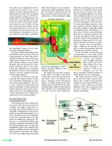
Figure 1 presents AMR system architecture in this pilot project. The communication step 2 between the concentrator and meters in the building is likely to be power line communication (PLC), radio frequency (RF), TCP/IP, 1-Wire or M-Bus communication (see Fig. 1). These are the most suitable communication options for the purposes of this research. The functionality and suitability of the data transmission in the building environment were studied.
Keywords- Data transmission, measurement, automatic meter reading
I. INTRODUCTION AMR would not just mean an cost reduction for energy companies including electric power, water, and gas, but would empower them with more efficient management capability for demand (or direct) control, energy monitoring [7]. With AMR, energy companies can remotely read electricity, water, gas and district heat meters by using an AMR system. The consumption data is stored by the host computer and utilized, for instance, in billing operations. Broadband networks offers new opportunities to enhance added value in the meter reading and companies can improve their real-time billing operations and also achieve cost-effective solutions in this market area. PLC enables new and highly convenient networking functions without any additional cables to mains-powered devices. It is the advantage of communication lines that digitalization and networking of existing facilities could be organized at low cost [3], [7]. Originally, power lines are used to supply electrical energy to machineries of various types, carrying low levels of impedance. Due to irregularity in their composition and the abrupt changes arising from load properties, using the power lines for any such other purpose as communication is unlikely to be successful [7]. AMR is much more than replacing consumption meters and providing more accurate customer bills. It is a pivotal information source that used effectively can drive company efficiencies within Transmission and Distribution (T&D)
c 1-4244-0113-5/06/$20.00 2006 IEEE.
Figure 1. The AMR-system architecture [9], [10]
208
As shown in figure 1, there are two existing communication line in the residential area, WLAN and a twisted pair cable line. Twisted pair cable lines perform district heat control and alarm tasks automatically and are in current use. All consumption meters are located inside the apartment buildings. The concentrator location is in the apartment building’s electrical control room. WLAN (IEEE 802.11b) links together both heating plant and the building’s base station (BS) devices [9], [10]. This study consists of four sections. Firstly, we present an AMR system pilot project plan and its implementation as it generally used in wireless technologies. The rest of this paper is organized as follows. In section 2 the measurements are taken. Measurement results and discussion of them follow in section 3. Finally, relevant conclusions are given in section 4. II.
MEASUREMENT SET-UP
Measurements on PLC promise high bit rate throughput. To achieve connections with a sufficient certainty, reasonable feeding power limits with coexistence rules like dynamic notching are essential [3]. Measurements of connection throughput were realized by measuring the throughput of file transfers over the FTP connection. The QoS parameters in this study were transfer speed, mean latency, jitter and retransmission. The retransmission percentage needs additional software for calculations. First we have to find out the sequence numbers of transmitted packages by using Ethernet network analyzers. After this, the sequence numbers are transferred to the spreadsheet program and retransmission is calculated by comparing the amount of sent and received packets. The retransmission percentage describes the data communication reliability in these measurements [9], [10].
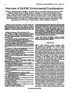
Figure 2. Measurement scenario [9], [10]
Latency and jitter are calculated by using the ping program and transfer speed by using a spreadsheet program. These parameters define the main aspects of data communication usability and QoS requirements. All measurements were taken in the pilot project building environment including measurement scenarios as follows [9], [10]: • Scenario 1: WLAN communication without base station devices • Scenario 2: WLAN communication consisting of PLCEthernet Bridge, base station devices, and customer antennas • Scenario 3: Measuring procedure with WLAN communication, from concentrator to the energy company premises • Scenario 4: Twisted pair cable measuring
Figure 3. PLC communication test scenario
• Scenario 5: Simulations
In measurement scenario 2 PLC-Ethernet Bridge, base station devices, and customer antennas were assigned to the measurement scenario. PLC-Ethernet Bridge (10/100 bridge) provides five adapters, two Ethernet and three USB based on Intellon’s A1 chip. PLC-Ethernet Bridge replaces the Ethernet cabling as shown in Fig. 2. PLC-Ethernet Bridge communication was firstly tested because disturbances may cause unsuccessful results if Ethernet communication does not
In this paper, we focused on the scenario 2 measurements and results. Functionally, the objective WLAN uses line-ofsight (LOS) technology and the distance between the base stations is 345 metres. Concerning the measurements it must be stated that no changes were made to the base stations or antenna settings. This maintained constant antenna polarization and direction [9], [10].
209
work properly [9], [10]. This test measurement scenario includes the cable reel in resolving the effects of external connected cable. This way we can assure a workable method for further measurements. Fig. 3 presents PLC communication test scenario.
As shown in Table II, transfer speed differences are very minor when comparing downlink and uplink direction. Of course, at a different time of day results could look very different. For that reason the same measuring procedure was carried out three times and at different times of day. Overall results are very much alike; therefore average results are represented in Table II. Also we did another test measurement in the office environment to get relevant reference values and test results when using additional cable. It appeared, that the most notable factors in PLC network reliability were: chosen outlet to supply PLC-Ethernet Bridge and the building environment where measurements were done. This indicates that there is a lot of variation in PLC network at the moment when measurements were done. Measurement results at two different distances including the cable reel are shown in Table III.
III. RESULTS AND DISCUSSION The results are clearly most subject to variation or disturbance when using PLC. This is probably caused by devices in the electrical network. What they are is not possible to define. Also the insufficient symmetry and the insufficient insulation of the mains wiring are the general reasons for EMC (Electro Magnetic Compliance) and transmission medium problems. Cables are designed for 50/60 Hz and not for high frequency applications; therefore they have high losses in the PLC frequency range, due to inadequate dielectric materials [6] - [10]. However, those difficulties can be identified in measuring results. Table I shows measured parameters in scenario 2 [9], [10]. TABLE I.
TABLE III.
MEASUREMENT PARAMETERS IN SCENARIO 2
PLC COMMUNICATION TEST AT DIFFERENT DISTANCES
Long distance (> 10 m)
Short distance (< 10 m)
Downlink [Mbps]
Uplink [Mbps]
Downlink [Mbps]
Uplink [Mbps]
1,8
0,5
0,6
1,5
Scenario 2 Step no.
Transfer speed [Mbps] DL UL
Latency [ms]
Jitter [ms]
Retransmission [%]
1
2,8
0,9
7-9
approx. 0
0
2
1,3
0,6
8
approx. 0
0
3
0,9
0,6
8-10
approx. 0
0
4
1,0
1,2
8-10
approx. 0
0
Because of different data traffic situations in the electrical network were another meaning for the test measurement with additional cabling. This measurement procedure gives particular information about what are the transfer speed values in normal utilization as reference. The measurement was done in our office environment and does not included in scenario 2 set-up in the apartment building. The results prove that transfer speed was reduced nearly 35 % in downlink direction and 44 % in uplink direction when comparing scenario 2 results in step 1 (2,8/0,9 vs. 1,8/0,5 Mbps). Results also show that time of day does not significantly affect the measurement network in Fig. 2. The size of the data packet was 50 Mb (52428869 bits).
As seen in the Table I, scenario 2 includes four measurement steps. The first phase (2,8/0,9 Mbps) is a test measurement without PLC communication. These are the reference values, which can be used for next measurement phases. We constructed an environment to support the sending of certain data packet through the link. The size of the data packet was 5 Mb (5243920 bits). For transferring the data packets we used WS_FTP software so that the packet was firstly sent in the downlink direction and then in the uplink direction. Thus, one PC operated as the FTP-client and the other PC as the FTP-server. In the second phase (see Fig. 2) PLC-Ethernet Bridge, base station devices, and customer antennas were assigned to the measurement scenario and we got results as 1,3/0,6 Mbps. Phase 3 values consist of customerbased traffic and they are connected as a client to the WLAN network. We also generated external data traffic from a third PC and the result is shown in phase four (1,0/1,2 Mbps). This also includes customer-based traffic like phase 3 [9], [10]. TABLE II.
IV.
In this pilot project, the effects of power line communication in the AMR system have been presented. As can be seen from measurements, network utilization and radiation interferences affect a lot the throughput of data transfer medium. In the PLC communication option, the transfer speed was reduced nearly 50 %, which is quite a lot. This is also shown in transfer speed reference measurement values (1,3/0,6 vs. 2,8/0,9 Mbps). Depending on the distance of power line and the structure of electrical network transfer speed could reduce over 65 %. PLC enables very economic and low material cost solution especially in the new building objects. Particularly, PLCEthernet Bridge offers high practical means for replacing normal Ethernet cabling and reducing installation costs.
RESULTS IN PLC COMMUNICATION TEST WITH ADDITIONAL CABLING
Measurement without cable reel
Measurement including cable reel
Downlink [Mbps]
Uplink [Mbps]
Downlink [Mbps]
Uplink [Mbps]
5,1
5,4
4,9
5,4
CONCLUSION
REFERENCES [1]
210
Y. Liu, R. A. Fischer, and N. N. Schulz, “Distribution system outage and restoration analysis using a wireless AMR system,” IEEE Power Engineering Society Winter Meeting, vol. 2, pp. 871 – 875, January 2002.
[2]
C. Brasek, “Urban utilities warm up to the idea of wireless automatic meter reading,” IEE Computing & Control Engineering Journal, vol. 15, pp. 10 – 14, December 2004 - January 2005. [3] A. Schwager, L. Stadelmeier, and M. Zumkeller, “Potential of broadband power line home networking,” IEEE Consumer Communications and Networking Conference, pp. 359 - 363, January 2005. [4] I. Steklac and H. Tram, “How to maximize the benefits of AMR enterprise-wide,” IEEE Rural Electric Power Conference, Pages: C5/1 C5/7, May 2005. [5] Metering International., http://www.metering.com/archive/031/36_1.htm [6] S. Battermann and H. Garbe, “Influence of PLC transmission on the sensitivity of a short-wave receiving station,” IEEE Power Line Communications and Its Applications, 2005 International Symposium, Pages: 224 - 227, April 2005. [7] B. S. Park, D. H. Hyun and S. K. Cho, “Implementation of AMR system using power line communication,” IEEE Transmission and Distribution Conference and Exhibition 2002: Asia Pacific, vol. 1, Pages: 18 - 21, October 2005. [8] K. Y. See, P. L. So, A. Kamarul, and E. Gunawan, “Radio-frequency common-mode noise propagation model for power-line cable,” IEEE Transactions, Power Delivery, vol. 20, Pages: 2443 - 2449, October 2005. [9] P. Oksa, M. Soini, J. Nummela, L. Sydänheimo and M. Kivikoski, “Reliability and usability in data transmission networks of the AMR system: a pilot stydy,” Proceedings of the 4th WSEAS Int. Conf. on Information Security, Communications and Computers, Tenerife, Spain, Pages: 388 - 393, December 2005. [10] P. Oksa, M. Soini, J. Nummela, L. Sydänheimo and M. Kivikoski, “Making AMR system more reliable,” 4th WSEAS Transactions on Communications, Issue 2, Volume 5, Pages: 161 - 167, February 2006.
211