IOP Conference Series: Earth and Environmental Science
PAPER • OPEN ACCESS
Considerations regarding open-source systems and equipment for UAV’s To cite this article: V Prisacariu et al 2018 IOP Conf. Ser.: Earth Environ. Sci. 172 012016
View the article online for updates and enhancements.
This content was downloaded from IP address 139.81.61.194 on 13/07/2018 at 01:43
4th International Scientific Conference SEA-CONF 2018 IOP Conf. Series: Earth and Environmental Science 172 (2018) 1234567890 ‘’“” 012016
IOP Publishing doi:10.1088/1755-1315/172/1/012016
Considerations regarding open-source systems and equipment for UAV’s V Prisacariu1, I Cîrciu1 and A Luchian2 1
Aviation Department, Henri Coandă Air Force Academy, 160 Mihai Viteazul street, Brașov, Romania 2 Engineering and Industrial Management Department, Transilvania University, 5 Mihai Viteazul street, Brașov, Romania Email:
[email protected] Abstract: Unmanned aerial vectors have become a mature technology that requires multidisciplinary and trans-disciplinary approaches based on airline typology. The technological level implemented has proven to be independent of the size of the air vector, which takes into account the missions, costs and limitations of the system. The article wishes to summarize the information about the automatic open-source APM 2.6 pilot for the construction and connection, programming and operation of the sensors used.
APM PCB IMU ADC ESC VTOL UCAV GUI
Acronyms: Ardupilot Mega Printed Circuit Board Inertial Measurement Unit Analogic Digital Convertor Electric Speed Controler Vertical Take-off Landing Unmanned Combat Aerial Vehicles graphical user interface
PPM GCS EPROM RC VFR USV MAVLink
Pulse Position Modulation Ground Control Station Erasable Programmable Read-Only Memory Radio Command Visual Flight Rules Unmanned Surface Vehicles Micro Air Vehicle Link
1. Introduction The equipment level of a UAS is reflected in the cost of design, manufacture, acquisition and operation. Like any technical system as a finished product, the operational UAS encompasses concepts, techniques and design and manufacturing methods and a set of requirements determined by manufacturing, operational and cost constraints, which may even be the objectives conception and design of the air system. 1.1. Brief history, evolution and classification The first preoccupations in the field of unmanned aircraft are recorded starting with 1483 Leonardo da Vinci and 1754 by Mihail Lomonosov [1, 2], and in 1843 George Cayley conceives and tests the convertoplan carriage, see Figures 1 and 2. [3]. The first pioneering attempt to use in a military conflict is recorded in 1880 when the Austrian bombs floated above Venice and in 1916 the first use of Archibald Montgomery Low's propelled air vehicle [4, 5]. The first attempt to use the autopilot concept was due to Elmer Sperry in 1914 at the Sperry Gyroscope, the functional model was put into practice after two years of research based on proportional control being used on a plane piloted for steering and altitude, the autopilot being connected to a gyroscopic position indicator and an altitude indicator, [12, 13].
Content from this work may be used under the terms of the Creative Commons Attribution 3.0 licence. Any further distribution of this work must maintain attribution to the author(s) and the title of the work, journal citation and DOI. Published under licence by IOP Publishing Ltd 1
4th International Scientific Conference SEA-CONF 2018 IOP Conf. Series: Earth and Environmental Science 172 (2018) 1234567890 ‘’“” 012016
Figure 1 Convertoplan carriage, George Cayley, [3]
IOP Publishing doi:10.1088/1755-1315/172/1/012016
Figure 2 Ruston Proctor Aerial Target, [5]
1.2. Development Trends Although the UAS technology consumer is the military domain (data acquisition and retrieval and UCAV) but in the last decade we have serious benchmarks in the civilian market regarding the use of these types of air systems in different areas of economy, tourism, environment and not the last row of education and research. The main development trends of the UAS domain concern VTOL capabilities to increase flight autonomy and expand operating environments (hybrid systems: UAV-UGV, USV-UAV, innovative batteries), increase autonomy level and intrinsic decision of the system (use of algorithms and techniques complex programming: fuzzy, genetic, probability), see figure 3, [7, 8, 9, 10].
a
b
Figure 3 Hybrids UAS, a.turbofan/solar hybrid UAV, [7]; b. Falcon-V VTOL, [8]. An unmanned airplane system with a high level of decision-making involves high-performance radio-electronic equipment, equipment that has cost-of-function and reliability in operation, a focus on open-source equipment that offers upgrades and almost limitless programming, a convincing example is provided by ATMega microprocessor development boards that led to the introduction of the autopilot products from the APM and Pixhawk family on the UAV market. APM 2.6 is open source electronic equipment that allows the transformation of a UAV into a fully autonomous unmanned aerial vector, the system is based on the hardware and software components as follows: 2.APM 2.6 hardware APM 2.6 is composed of two PCBs on which the pilot components are mounted. The plaque containing the automatic pilot is called ArduPilot Mega, and the board on which the sensors are positioned is called the IMU Shield. Together, these two plates are the brains of the system, the IMU plate compiles and transmits the sensor information, and the ArduPilot Mega plate analyzes this information and acts in accordance with the way the automatic pilot was programmed. The two boards have analog and digital inputs for different sensors and modules that can be connected.
2
4th International Scientific Conference SEA-CONF 2018 IOP Conf. Series: Earth and Environmental Science 172 (2018) 1234567890 ‘’“” 012016
IOP Publishing doi:10.1088/1755-1315/172/1/012016
2.1.ArduPilot Mega This electronic board deals with routing the UAV, it receives information from the sensors that are available, analyzes the data and acts as planned. From it, all commands that trigger the 3D space of the drones leave. The UAV's spatial motion is accomplished by varying the engine speed (multicopter) or the position of the control surfaces (airplanes). The main components and their layout on this PCB can be seen in Figure 4: 1-pin input, 2-pin PPM, 3-button RESET, 4/6/9-pin IMU, 5-port ATMega 1280, 7-way automatic, 8-pin GPS connection, 10-multiplexer, 11-pin power supply, 12-pin I/O data.
Figure 4 ArduPilot Mega, [11].
Figure 5 IMU Shield
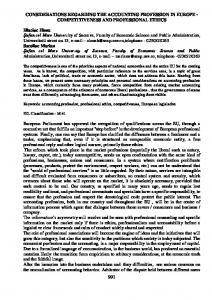
2.2.IMU Shield The basic component of the IMU Shield is the PCB board (see the layout of the components in figure 5), the following components are mounted on the board: 1-port USB with 2-chip USB support, Z-axis 3-gyroscope, 4-button RESET, analog-digital converter, 6-pressure sensor, 7-port analog sensors, 8/12/14-pin ArduPilot Mega I/O data, 9-megapixel flash memory, 10-pin Pitot tube connection - 13port connection external magnetometer, 15-magnetometer, 16-accelerator with three axes, 17switches, 18-gyroscopes X, Y, 19-trigger axes. The integrated commercial version of APM 2.6 has a unitary architecture and a protective case as shown in Figure 6.
Figure 6 APM 2.6, [17] 3. APM 2.6 software The software resources used to operate the unmanned air vehicle are divided into programming resources and firmware resources.
3
4th International Scientific Conference SEA-CONF 2018 IOP Conf. Series: Earth and Environmental Science 172 (2018) 1234567890 ‘’“” 012016
IOP Publishing doi:10.1088/1755-1315/172/1/012016
3.1. Programming resources They consisted of various software components that control hardware components via firmware. The program used in APM 2.6 is the Arduino IDE, [14] needed to update the firmware with new features or to create a new firmware, Arduino uses a C ++ like programming language. Example of integration of resources in APM architecture. The GPS module. Putting into operations of the GPS module on the APM 2.6 automatic pilot assembly involves both connecting the GPS receiver connector to the port on the ArduPilot Mega board (Figure 7) and writing the programming code.
Figure 7 GPS connection in the multicopter architecture, [15] The "#include" operator inserts the firmware code so that the automatic pilot recognizes the information received from the GPS (Figure 8a). "RxGPS 3" and "TxGPS 5" designate pins 3 and 5 for receiving and transmitting data from and to the GPS receiver. The data transmission rate is 4800 bps. "Void loop" provides the read cycle for receiver location, and "Serial.println (s);" allows the display of coordinates in the "Serial Monitor" window (Figure 8b).
a
b
Figure 8 Integration of GPS module into APM 2.6, [14] The "Serial Monitor" window opens from the "Tools" menu of the Arduino program. Before the GPS firmware is loaded, press the "Verify" button to check for errors in the code, and then click the "Upload" button. To check if the GPS interacts with the autopilot, it should be noticed if the green light is on and the blue light is blinking. The green LED alerts the user that the GPS receiver is connected to the
4
4th International Scientific Conference SEA-CONF 2018 IOP Conf. Series: Earth and Environmental Science 172 (2018) 1234567890 ‘’“” 012016
IOP Publishing doi:10.1088/1755-1315/172/1/012016
ArduPilot 2.6 board and receives electricity, the flashing blue LED cautions the user that the GPS receiver has located its position. The source code is highlighted below: #define rxGPS 3 #define txGPS 5 GTPA010 serialGPS = GTPA010 (rxGPS, txGPS); String stringGPS = ""; void setup() { pinMode(rxGPS, INPUT); pinMode(txGPS, OUTPUT); Serial.begin(9600); Serial.println("Started"); serialGPS.begin(4800); digitalWrite(txGPS,HIGH); while(serialGPS.available()) if (serialGPS.read() == '\r') break; } void loop() { String s = checkGPS(); if(s && s.substring(0, 6) == "$GPGGA") { Serial.println(s); }} 3.2. Firmware resources The firmware is a set of basic instructions written on the non-volatile memory chip. These instructions enable a small number of input/output (I/O) hardware components, but more importantly, it makes possible communication between hardware and software that control the hardware. Depending on the type of memory used, PROM or EPROM, the firmware can be deleted and rewritten to add new features. In case of APM 2.6, the firmware resource instructs the pilot automatically how to recognize input data from different sensors and how to use them. For example, input data from gyros are used to stabilize the three axes of the drones. The course of these data is as follows: the electronic gyroscopes on the IMU board measure the attitude difference from the reference axes and continuously send signals to the ADC signal converter, it takes the signals and converts them into binary data by sending them further to the automatic pilot on ArduPilot Mega electronic board.
Figure 9 Sensor-microcontroller data connections and execution element: 1-gyroscope, 2- automatic pilot, 3-board distribution current, 4-electric motor. It analyzes the information and sends pulses to the power distribution board from where the energy is distributed, according to the instructions of the autopilot, to the electric motors. A schematic of this example can be seen in Figure 9.
5
4th International Scientific Conference SEA-CONF 2018 IOP Conf. Series: Earth and Environmental Science 172 (2018) 1234567890 ‘’“” 012016
IOP Publishing doi:10.1088/1755-1315/172/1/012016
APM Plane, APM Copter, APM Antenna Tracker, Mission Planner, APM Planner, is the APM planner resources for APM applications, [16]. Mission Planner Mission Planer as APM Planner is a software tool installed on the ground control station (GCS) for the APM 2.x and Pixhawk series for low cost open-source systems. Mission Planer allows: updating the automatic pilot firmware (Figure 10a); live reading of telemetry data and reading offline sensor data (Figure 10b); setting up and adjusting the autopilot system and planning a flight mission; connecting with a flight simulator; downloading log files and analyzing them, [17, 18].
b
a
Figure 10 Mission Planner GUI, a. Firmware choice, b. Live telemetry data read Reading telemetry data allows you to view some operating parameters such as: UAV (pitch, yaw, roll) and speed data on the three axes; data about GPS parameters (position, speed, altitude, compass head), see Figure 11; mission type data; data on navigation and servo output signals (see Figure 12); data about radio signals.
a
b
Figure 11 GPS flight parameters, flight altitude, b. compass
a
b
Figure 12 GPS flight parameters, a.pitch-yaw-roll, b. output signals
6
4th International Scientific Conference SEA-CONF 2018 IOP Conf. Series: Earth and Environmental Science 172 (2018) 1234567890 ‘’“” 012016
IOP Publishing doi:10.1088/1755-1315/172/1/012016
Flight data can be viewed and analyzed from dataflash logs to diagnose mechanical defects, vibrations, magnetic interference, or engine operation, these flaws occurring in the form of pitch, roll, or girth leaps. Vibrations with significant values can be read by displaying data provided by accelerometers (AccX, AccY, AccZ values) of IMU messages for horizontal position control. Magnetic interferences that may be generated by the power distribution board, motors, accumulators, ESCs can cause malfunction of the compass that causes unwanted UAVs, these interferences can be viewed at CUSTOM / VFR_HUD. The Flight Data View interface also allows data export in *.txt, *.csv, and Matlab files for postprocessing and numerical analysis. Conclusions Unmanned aerial vectors have become a mature technology that requires multidisciplinary and transdisciplinary approaches based on airline typology. The technological level implemented has proven to be independent of the size of the air vector, a level that takes into account the missions, costs and limitations of the system. Opensource systems and equipment such as Ardupilot Mega (APM) opened new opportunities in the UAV market and the nonprofit segment with significant effects on operating and mission concepts such as data acquisition in areas of interest in completely autonomous platforms. APM has opensource features and a simple process to load and install the firmware, programming knowledge is only needed if new lines of code are created using Arduino. APM is capable of both bidirectional telemetry with the MAVLink protocol and possibilities for setting ground and air parameters for mission planning and re-planning, on-board video display and data storage. APM is designed and designed for easy integration of most types of UAVs, unmanned land-based vehicles (UGVs), unmanned surface / underwater vehicles (USV/UUV) and ground station control. Acknowledgment The National Authority for Scientific Research, Romania supported this work – CNCS-UEFISCDI: with PN-III-P2-2.1-PED-20161972, MAPIAM project, contract 65PED/2017. References [1] [2]
[3] [4] [5] [6] [7] [8] [9] [10]
[11] [12]
Valavanis K.P., Advances in Unmanned Aerial Vehicles, USA, 2007, ISBN 978-1-4020-6113-4, www.springer.com Dalamagkidis K et al., On Integrating Unmanned Aircraft Systems into the National Airspace System, Intelligent Systems, Control and Automation: Science and Engineering 54, DOI 10.1007/978-94-0072479-2 2, Springer http://www.aviastar.org/helicopters_eng/cayley.php, accessed at 26.02.2018 Barnhart R.K., Hottman S.B., Marshall D.M., Shappee E., Introduction to unmanned aircraft systems, CRC Press, 2012, ISBN 978-1-4398-3520-3, 215p. https://skyward.io/marilyn-monroe-and-the-origin-of-drone. accessed at 28.02.2018 Prisacariu V., Boşcoianu M., Luchian A., Innovative solutions and UAS limits, REVIEW OF THE AIR FORCE ACADEMY, 2(26)/2014, Braşov, Romania, ISSN 1842-9238; e-ISSN 2069-4733, p51-58. Erdinç Mermer, Serkan Özgen, Conceptual design of a hybrid (turbofan/solar) powered HALE UAV, 7th European Conference for Aeronautics and Space Sciences (EUCASS), doi: 10.13009/EUCASS2017-200, p19. Flacon-V VTOL UAV, disponibil la http://www.top-enggroup.com/product.htm, accessed at 14.03.2018 Daeil Jo, Yongjin Kwon*, Analysis of VTOL UAV Propellant Technology, Journal of Computer and Communications, 5/2017, p. 76-82, ISSN Online: 2327-5227, https://doi.org/10.4236/jcc.2017.57008 Office of the Assistant Secretary of Defense for Research and Engineering, Rapid Reaction Technology Office, Lighter-than-air vehicles, 90p, available at http://www.defenseinnovationmarketplace.mil/ resources/Final_LTA_report.pdf, 2012 http://newlab.westernwillow.com/component/ardupilot-mega-2560-oilpan-h, accesed at 12.02.2018 S. Bennett, Nicolas Minorsky and the Automatic Steering of Ships. 1984, p10-15, available at http://ieeecss.org/CSM/library/1984/nov1984/w10-15.pdf
7
4th International Scientific Conference SEA-CONF 2018 IOP Conf. Series: Earth and Environmental Science 172 (2018) 1234567890 ‘’“” 012016
[13]
[14] [15] [16] [17] [18]
IOP Publishing doi:10.1088/1755-1315/172/1/012016
Ingrid Hagen Johansen, Autopilot Design for Unmanned Aerial Vehicles, Norvegian University of Science and Technology, 2012, p.108, available at https://daim.idi.ntnu.no/masteroppgaver/007/7001 /masteroppgave.pdf https://www.arduino.cc/en/Main/Software, accessed at02.03.2018 http://ardupilot.org/copter/docs/connecting-the-apm2.html, accessed at05.03.2018 http://firmware.ardupilot.org/, accessed at 05.03.2018 Oborne M., Samantha Nelson, Practical Work II Introduction to Mission Planner and APM Autopilot, 24p., available at www.comp.nus.edu.sg/~ctank/uav/Practical%20Work%20II.pdf, accessed at 08.03.2018 Deploying ardupilot, 29p., available at www.bandung-aeromodeling.com/tutorials/APM-TS40.pdf, accessed at 08.03.2018
8