382
JOURNAL OF COMMUNICATIONS, VOL. 7, NO. 5, MAY 2012
Constrained Group Decoder for Interference Channels Chen Gong∗ , Omar Abu-Ella∗ , Xiaodong Wang∗ , Ali Tajer† , ∗
Department of Electrical Engineering, Columbia University, New York, NY 10027, USA Email: {chengong, omar, wangx}@ee.columbia.edu, † Department of Electrical Engineering, Princeton University, B-311 E-Quad, Olden Street, Princeton, NJ 08544, USA, Email:
[email protected].
Abstract— We provide a general overview of the recent development on the constrained group decoder (CGD) for interference channels. We first consider the CGD for a simple system of interference channels with no feedback from the receivers to the transmitters, where the transmitters employ fixed-rate channel codes and modulation schemes. We provide simulation results to show that, compared with the interference suppression scheme that maximizes the signal-to-interference-plus-noise ratio (SINR) at the receiver and the one that minimizes the interference leakage to the signal subspace (i.e., interference alignment), the group decoder offers an signal-to-noise ratio (SNR) gain of around 5dB at the outage probability 3 × 10⁻² and bit error rate (BER) 2 × 10⁻³ . We then discuss the application of the CGD to more sophisticated systems that allow feedback from receivers to transmitters. More specifically, we review the recently developed practical coding schemes for the constrained partial group decoder (CPGD) and the group decoder for the multi-relay-assisted interference channels. Compared with the interference alignment approach, the group decoding paradigm not only provides substantial performance gains, but also eliminates the need of feeding back the channel state information of all users to the transmitters, thus significantly reducing the system signaling overhead. Index Terms— interference channel, group decoder, channel codes, relay.
I. I NTRODUCTIONS The interference channel is a fundamental building block of wireless networks. Due to the ever-shrinking network sizes and the increasing demands for achieving higher spectral efficiency, the emerging wireless networks will operate in an interference-limited regime. Motivated by this, various recent developments for further understanding the fundamental limits of interference channels based on interference alignment have appeared [1], [2], [3], [4]. The idea of interference alignment is to process the transmit signals at the transmitters such that after some projection each receiver only sees the signal from its designated transmitter, but not the interference. From the theoretical point of view, it achieves the optimal degree of This paper is based on “Group Decoding for Interference Channels,” by C. Gong, A. Tajer, and X. Wang, which appeared in the Proceedings of the International Conference on Computing, Networking and c 2005 IEEE. Communications, Maui, Hawaii, USA, Feb.2012. ° Manuscript received February 15, 2011; revised May 15, 2011; accepted June 15, 2011.
© 2012 ACADEMY PUBLISHER doi:10.4304/jcm.7.5.382-390
freedom in the asymptotic regime of high signal-to-noise ratio (SNR) [1]. On the other hand, from the practical point of view, various signal processing schemes for interference alignment have been proposed in [5], [6], [7]. In [5], a practical distributed interference alignment scheme is proposed, which requires only local channel knowledge. However, the method has a very high computational complexity and it relies on the assumption of channel reciprocity which may not hold true in practice. Thus, beamforming-based approaches are still considered viable and practical alternatives to interference alignment. Recently, two beamforming methods have been proposed for interference alignment, based on maximizing the received signal-tointerference-plus-noise ratio (SINR) [6] and minimizing the interference leakage to the signal subspace at the receivers [7], respectively. Note that the above approaches are all based on the idea of interference suppression, where all interference should be suppressed and treated as noise through transmitter-end signal processing. On the other hand, it is well-understood that while a receiver is not ultimately interested in decoding the messages of the interferers, decoding them (fully or partially) is often advantageous for recovering its desired message [8]. Motivated by this premise some recent works on interference channels propose that each receiver should partition the interfering transmitters into two groups; one group to be decoded along with the designated transmitter and the other to be treated as Gaussian noise [9], [10], [11]. In this paper we provide an overview of the recent development on such group decoding approach to interference channels. We first consider a simple interference channel system without feedback from the receivers to the transmitters, where due to the lack of feedback all interference management is performed at the receiver side. We also assume that each transmitter employs a fixedrate channel code and modulation scheme. Based on the optimal group decoding order obtained from a greedy algorithm, each receiver employs a constrained group decoder (CGD) to successively decode some interferers and the desired user. Simulation results show that the group decoder outperforms the SINR maximization [6] and interference leakage minimization [7] schemes by approximately 5dB at the outage probability 3 × 10⁻²
JOURNAL OF COMMUNICATIONS, VOL. 7, NO. 5, MAY 2012
383
and bit error rate (BER) 2 × 10⁻³ . We further review two extensions of the above group decoder, namely, the constrained partial group decoder (CPGD) for a K-user interference channel and the CGD for a multi-relay-assisted interference channel. For the CPGD, we outline a practical coding scheme for a K-user interference channel, which further divides each transmitter into multiple layers, to provide the receivers with the freedom of deciding on which interferers to decode as well as what fraction of each interferer need to be decoded. For the CGD in multi-relay-assisted interference channel, we discuss the rate allocation among the users in a half-duplex multi-relay-assisted K-user interference channel. The remainder of this paper is organized as follows. In Section II, we describe the K-user fully connected interference channel. In Section III, we discuss the CGD with fixed-rate channel codes and modulation scheme. In Sections IV and V, we overview the practical CPGD coding scheme and the CGD for the multi-relay-assisted interference channel, respectively. Finally, Section VI concludes this paper. II. F ULLY C ONNECTED K- USER I NTERFERENCE C HANNEL Consider a fully connected K-user interference channel. We denote the wireless channel from the j th transmit4 ter to the ith receiver by hi,j for i, j ∈ K = {1, . . . , K}. We assume quasi-static block fading channels such that the channel coefficients are fixed during the transmission of a symbol block and change to some other independent states afterwards. By defining xj as the transmitted signal by the j th transmitter, the received signal by the ith receiver is given by yi =
K X
hi,j xj + vi ,
for i ∈ {1, . . . , K} ,
(1)
j=1
where vi ∼ NC (0, σ 2 ) accounts for the additive white Gaussian noise (AWGN) at the ith receiver. The term hi,i xi contains the intended signal for the ith receiver and the remaining summands constitute interference and noise. Denote the equal transmission power of all trans4 mitters as P = E(|xj |2 ). Assume that each receiver i is only interested in decoding the message of transmitter i, but aware of the codebooks used by all the transmitters. Note that the single-antenna interference channel model can be extended into the multiple-input-singleoutput (MISO), single-input-multiple-output (SIMO), and multiple-input-multiple-output (MIMO) models. In the following we describe the SIMO interference channel, where each receiver i employs Ni receiving antennas. Let hi,j be the channel from the j th transmitter to the ith receiver and y i be the received signals of the ith receiver. We have the following yi =
K X
hi,j xj + v i ,
j=1
© 2012 ACADEMY PUBLISHER
for i ∈ {1, . . . , K}
(2)
where v i ∼ NC (0, σ 2 I) accounts for the additive white Gaussian noise (AWGN) at the ith receiver. Denote the 4 equal transmission power of all transmitters as P = 2 E(|xj | ). III. C ONSTRAINED G ROUP D ECODER We consider the CGD for the above K-user interference channel, where there is no feedback from the receivers to the transmitters and the transmitters employ fixed-rate channel codes and modulation schemes, and each user is aware of the coding scheme employed by all other users. A. Successive Group Decoder We formalize the successive group decoder (SGD) employed by the receivers. Each stage a subset of the users are jointly decoded, after subtracting the already decoded users from the received signal, and by treating the remaining users as AWGN. In order to control the decoding complexity, we constrain the number of users being jointly decoded at each stage to be at most µ. Let Rj be the rate of transmitter j, and RA = [Rj ]j∈A for A ⊆ K. For each receiver i, we say that a given ordered 4 partition G i = {G1i , . . . , Gpi i , Gpi i +1 } of K is valid if all the following conditions are satisfied. i 1) |Gm | ≤ µ for m ∈ {1, . . . , pi }; 2) Transmitter i, i.e., {xi }, is included in Gpi i ; th i is decodable at the m 3) The rate vector RGm stage of the successive decoding procedure for m ∈ {1, . . . , pi }. For a given valid partition G i of K, the ith receiver decodes the users included in {G1i , . . . , Gpi i } successively in pi stages while those in Gpi i +1 are always treated as AWGN. More specifically, in the mth stage, the ith i receiver jointly decodes the users in Gm by treating i i {Gm+1 , . . . , Gpi +1 } as AWGN and then subtracts the i from the received signal. decoded messages in Gm For the K-user SIMO interference channel [c.f. (2)] 4 √ under consideration, we let H i = [ P hi,j ]j∈K and 4 √ 4 H i,A = [ P hi,j ]j∈A , and xA = [xj ]j∈A for A ⊆ K. 4 Given the ordered partition G i = {G1i , . . . , Gpi i , Gpi i +1 }, receiver i performs the following pi -stage successive decoding. 1) Initialize m = 1; 2) Compute the covariance matrix of the interferenceplus-noise as follows, X (3) hi,j hH Σi,m = σ 2 I + i,j . p +1
i j∈∪k=m+1 Gji
i Then, decode the users in Gm from −1
−1
i xG i + v i,m , r i,m = Σi,m2 y i = Σi,m2 H i,Gm m
(4)
where v i,m ∼ NC (0, I) is the additive white Gaussian noise with unit variance.
384
JOURNAL OF COMMUNICATIONS, VOL. 7, NO. 5, MAY 2012
i 3) After decoding Gm , receiver i subtracts the decoded i signals xGm from y i via updating y i ← y i − i x H i,Gm . i Gm 4) If m = pi+1 then stop; otherwise go to step 2. We employ channel codes with error decoding detection capability, e.g., low-density parity-check (LDPC) codes. If a decoding error event in step 2 is detected, stop decoding and claim a decoding outage. In Fig. 1, we show a simple illustrative example of the SGD for an interference channel with four transceiver pairs. We show the SGD at receiver 3. As shown in Fig. 1, user 2 is decoded in the first stage; and users 3 and 4 are decoded in the second stage. After the two stages, user 3 are decoded and the decoding terminates. We have p3 = 2, Q31 = {2}, Q32 = {3, 4}, Q33 = {1}.
Q13
Q23
{2}
{3, 4}
Q33 {1}
Figure 1. A simple illustrative example for SGD.
B. Optimal Successive Group Decoder In the successive decoding, a rate outage is defined as an event that in some stage the rates of decoded users fall out of the achievable rate region assuming that the users employ Gaussian codebooks. More specifically, for two disjoint subsets A, B ⊆ K, and the spectrum rate R of the users, we define the following rate margin for decoding A while treating B as noise, ε(H i , A, B, R) ,
min
D⊆A,D6=φ
{∆(H i , D, B, R)}
max ε(H i , G i , R). i G
∆(H i , D, B, R) ¯ ¯ X ³ ´−1 ¯ ¯ H ¯ log ¯¯I + H H I + H H H Rj . i,B i,D ¯ − i,D i,B
G ∗ = arg
1≤m≤pi
(7) as the minimum rate margin through the pi -stage successive decoding. The rate outage at receiver i is equivalent to ε(H i , G i , R) < 0. To minimize the rate outage probability, each receiver i needs to find a partition G i © 2012 ACADEMY PUBLISHER
ε(H i , G, S \ G, R).
(9)
Algorithm 1 Greedy Partitioning for Fixed Rates R i 1: Initialize S = K, Gopt = φ. 2: Identify a group G ∗ = arg maxG⊆S,|G|≤µi ,G6=∅ ε(H i , G, S \ G, R). 3: If ε(H i , G ∗ , S \ G ∗ , R) < 0, then 4: declare a rate outage and stop; 5: else 6: update S ← S\G ∗ and G iopt ← {G iopt , G ∗ }; 7: if i ∈ G ∗ , then 8: output G iopt , and stop; 9: else 10: go to Step 2; 11: end if 12: end if Algorithm 2 Selecting an Optimal Group 1: 2: 3: 4: 5:
(6) 4
max
G⊆S,|G|≤µi ,G6=∅
Based on the submodularity of the achievable rate function, it can be proved that such greedy partition leads to an optimal solution to (8). If in some step, the selected G ∗ leads to the rate margin ε(H i , G ∗ , S \ G ∗ , R) < 0, then declare a rate outage event. The optimal group search problem (9) can be solved using simple exhaustive search via enumerating all possible nonempty set G ⊆ S with |G| ≤ µi and finding the one which maximizes ε(H i , G, S \ G, R). The exhaustive method can be applied for small µi , e.g., µi = 1 or 2, which is the case for most practical scenarios. For large µi , (9) can be efficiently solved using Algorithm 2 as follows.
j∈D
Moreover, for a partition G i = {G1i , . . . , Gpi i , Gpi i +1 }, we define © ¡ ¢ª i i , K \ ∪m , ε(H i , G i , R) , min ε H i , Gm j=1 Gj , R
(8)
Algorithm 1 performs the optimal group partition in a greedy manner. In each step, assuming the undecoded set to be S, receiver i finds the optimal set of the decoded users G ∗ as follows
(5)
for A = 6 φ and ε(H i , ∅, B, R) = 0, where
,
which maximizes ε(H i , G i , R), i.e., solving the following optimization problem
6: 7: 8: 9: 10:
4
Let S = {G ⊆ S : G = 6 φ, |G| = µi or G = S} and set S1 = φ, δ = −∞. For each G ∈ S, repeat update S1 ←− {S1 , G}; determine a = minW⊆G,W6=φ ∆(H i , W, S\G, RW ), ˆ be the minimizing set with and let W the smallest cardinality; if δ < a, then set A = G and δ = a; ˆ update G ←− G\W; until G = φ or G ∈ S1 ; end for Output G ∗ = A, ε(H i , G ∗ , S \ G ∗ , R) = δ and stop.
C. Simulation Results We consider a SIMO K-user interference channel given by (2) with K = 3 transceiver pairs and each receiver i
JOURNAL OF COMMUNICATIONS, VOL. 7, NO. 5, MAY 2012
0
10
Outage probability
OSGD MIL ILS
−1
10
−2
10
0
3
6
9
12
15
SNR (dB) Figure 2. Outage probability performance for OSGD with rate-1/2 channel codes and QPSK.
−1
10
OSGD MIL ILS
−2
10
BER
employs Ni = 3 receiving antennas. We assume that the channel hi,j ∼ NC (0, I Ni ) drawn from i.i.d. complex Gaussian distribution with zero mean and unit variance, the complex additive white Gaussian noise (AWGN) v i ∼ NC (0, I Ni ). All transmitters employ a rate-1/2 LDPC code with the block length of 5400 bits, and QPSK modulation; and the receivers employ soft demodulation and soft LDPC decoding to decode the messages of the transmitters. We assume that each receiver employs SGD with the group size constraint µi = 2 for all users, and Algorithms 1 and 2 to determine the optimal decoding order of the users. We evaluate the performance of the system, in terms of outage rate and BER. We count the system outage rate and the BER is computed based on the actual system performance, which includes both the rate outage predicted by the group partition (Algorithm 1) and the decoding error in the employed LDPC codes. The system outage rate and the BER of the OSGD are plotted against the SNR P/σ 2 from 0dB to 15dB, as shown in Figs. 2 and 3, respectively. We compare the performance of the OSGD with that of the two interference suppression schemes, the iterative least squares (ILS) algorithm [6] and the minimizing interference leakage (MIL) scheme [7], which employs receiver filtering to maximize the receiving SINR and minimize the interference leakage, respectively. It is seen that, compared with the two interference suppression schemes, the OSGD achieves around 5dB performance gain at the outage probability 3 × 10⁻² and bit error rate (BER) 2 × 10⁻³ .
385
−3
D. Comparison with Interference Alignment We have compared the performance of the OSGD with that of a practical interference alignment scheme (the MIL scheme). Note that the MIL scheme tailors the key idea of interference alignment for practical scenarios, where it is difficult or impossible to completely remove all interference. Around 7dB performance gain at the outage probability 5 × 10⁻² and BER 2 × 10⁻³ over the MIL scheme is observed. Moreover, in terms of the practical system implementation, in contrast to the interference alignment scheme, the group decoder does not require the feedback of all channel state information to the transmitters, i.e., each transmitter either needs to know only its own channel to do some simple beamforming. For example, each transmitter could perform channel-matched beamforming, in which case only its own channel needs to be fedback; or each transmitter could perform random beamforming, in which case no feedback is needed at all. In both cases, the interference is treated at the receiver by the group decoder. Hence compared with the interference alignment approach, the group decoder not only offers substantial performance gain, but also significantly reduces the signaling and feedback overhead of the system. © 2012 ACADEMY PUBLISHER
10
−4
10
0
3
6
9
SNR (dB)
12
15
Figure 3. BER performance for OSGD with rate-1/2 channel codes and QPSK.
IV. C ONSTRAINED PARTIAL G ROUP D ECODER In this section we discuss an enhanced version of the group decoder, i.e., the constrained partial constrained group decoder for a K-user interference channel [12]. A. Layered Encoding by Signal Superposition We consider single-antenna K-user interference channel model as in (1). To maximize the sum rate of all users, the message of each transmitter is split into layers each drawn from an independent codebook (rate splitting). Denote the number of codebooks (layers) of transmitter j
386
JOURNAL OF COMMUNICATIONS, VOL. 7, NO. 5, MAY 2012
by Lj . Denoting the signal of layer k by xj,k , we obtain yi =
K X j=1
hi,j
Lj X
xj,k + vi , i ∈ {1, . . . , K},
(10)
k=1
where vi ∼ NC (0, σ 2 ) accounts for the additive white Gaussian noise (AWGN). Assume that all transmitters employ an equal power P , and that all layers of transmitter j employ an equal power E(|xj,k |2 ) = LPj . B. Constrained Partial Group Decoding (CPGD) Each receiver i employs a pi -stage successive de4 coding described by an ordered partition G i = {G1i , . . . , Gpi i , Gpi i +1 } of K (the set of the indices of all i codebooks). All layers of transmitter i, i.e., {xi,k }L k=1 , i i are included in {Q1 , . . . , Gpi } such that they can be decoded in the pi -stage decoding. In the mth stage, 1 ≤ m ≤ pi , the ith receiver jointly decodes the layers i in Gm by treating ∪`>m G`i as AWGN and then subtracts i the decoded messages in Gm from the received signal. To control the decoding complexity, we constrain that i |Gm | ≤ µ for m ∈ {1, . . . , pi }. A key problem for CPGD is how to partition the groups G i for 1 ≤ i ≤ K and allocate the rates for all layers. An iterative joint rate allocation and group partition algorithm is developed in [12], that maximizes the minimum rate increments of the layers. C. Practical Coding Scheme A practical coding scheme based on the CPGD is given in [12], which consists of the following three steps: • user inactivation and message layering; • transmission mode selection; • rate enhancement. We describe the three-step practical coding scheme based on an illustrative example shown in Fig. 4. Assume that we have a discrete spectrum rate table T = {d1 , d2 , d3 , d4 }. In the first step we perform tentative rate allocation to the users and divide the users into multiple layers, and inactivate the users (layers) with rate smaller than d1 (not implementable). Assume that after the user inactivation and message layering, based on the threshold rate d1 , user 2 is inactivated and users 1 and 3 are divided into 2 layers, (1, 1), (1, 2), (3, 1), (3, 2), and (4, 1). In the second step, in order to find some implementable rates close to those yielded by the first step we quantize the rates according to the quantization rate table T = {d1 , ..., dT }. Assume that in the transmission mode selection, the rates of the five layers (1, 1), (1, 2), (3, 1), (3, 2), and (4, 1) are quantized to be d1 , d2 , d3 , d1 , and d4 , respectively, i.e., the number of information bits assigned to these layers are N d1 , N d2 , N d3 , N d1 , and N d4 , respectively, where N is the nominal number of transmitted symbols. As the quantized rates must be decodable, each quantized rate is smaller than its original counterpart which incurs some loss in spectral efficiency. © 2012 ACADEMY PUBLISHER
In the final step, we compensate for such loss by increasing the rates of layers beyond their quantized values and make them as close as possible to the original rates. The rate enhancement is performed via reducing the number of transmitted symbols to η ∗ N for some η ∗ < 1, and thus the rate of the five layers are enhanced to d1 /η ∗ , d2 /η ∗ , d3 /η ∗ , d1 /η ∗ , and d4 /η ∗ , respectively. The quantization table T = {d1 , ..., dT } needs to be optimized to maximize the sum rate of all layers obtained from the above three-step scheme. The optimization is done offline based on a training set of channel samples. D. Raptor Codes We use the doped Raptor code [13] with a rate-0.95 IRA precode for the following two reasons. Firstly, it exhibits near-capacity performance for both single-user channel and two-user multiple-access channel. Secondly, the online fine tuning can be easily implemented by the employed doped Raptor codes. All transmitters perform incremental transmission, via first transmitting the number of channel symbols given by the fine tuning, and then each time transmitting a certain number of channel symbols until all receivers successfully decode their desired messages. The profiles of Raptor codes are optimized using the extrinsic information transfer (EXIT) functions, to minimize the gap of the practical coding scheme to the Gaussian modulation and infinite-length codes. An interesting result for the profile optimization is that the gap for µ = 1 is significantly smaller than that for µ = 2. This is because for µ = 2, one user may be decoded individually or jointly with another user, so that we need to find a good code profile for both the single-user decoding and the two-user joint decoding. Due to the large gap for µ = 2 using practical codes, it suffices to have a group size of one in CPGD, which has a low complexity to achieve most of the performance gain for practical implementations. E. Results Consider a single-antenna interference channel with K = 6 transceivers. For i, j ∈ {1, . . . , K}, the channel coefficients hi,j are distributed as NC (0, 1). Assume that the size of the rate quantization table is |T | = 4. We let the group size µ = 1 and employ the optimized code profile and rate quantization tables of the layered and un-layered coding. Fig. 5 shows the corresponding throughput, denoted as “layered, optimum” and “un-layered, optimum”, respectively, for the channel SNR P/σ 2 from 0dB to 9dB. At each channel SNR, 1000 channel realizations are simulated and the throughput is the total number of information bits divided by the total number of transmitted symbols of the incremental transmission. For comparison, we plot the throughput performance of the rate table T = {0.40, 0.80, 1.20, 1.60} for the layered and un-layered coding schemes, denoted as “layered uniform” and “un-layered uniform”, respectively. It
JOURNAL OF COMMUNICATIONS, VOL. 7, NO. 5, MAY 2012
Number of Information Bits (1,1) Nd1
User Inactivation and Message Layering (1,1) User 1 (1,2)
User 4
Nd2
T = {d1,d2,...,dT}
(4,1)
(4,1) Design {d2,...,dT}
Design d1
Rate Enhancement
(1,2)
rate d2/Ș*
(3,1)
Nd1
(3,2)
rate d1/Ș*
(1,1)
Nd3
(3,1)
(3,1) (3,2)
d1
(1,2)
Transmission Mode Selection
User 2 User 3
387
rate d3/Ș*
(3,2) rate d1/Ș* Nd4
(4,1)
rate d4/Ș*
Ș*N Ș*N: number of transmitted symbols
N
Design T = {d1,d2,...,dT}
Figure 4. A simple illustrative example for the practical coding scheme for CPGD.
is seen that the optimized T provides larger throughputs. Furthermore, to show the performance gain of the code profile optimization, we plot the throughput of Luby’s profile for the layered and un-layered coding schemes with the same optimized T as that for the optimized profile. It is seen that the optimized profile significantly outperforms Luby’s profile.
3.6 3.4 3.2
system trhoughput
3 2.8 2.6 2.4
Let fn,j , hi,j , and gi,n denote the channel gain from source j to relay n, from source j to destination i, and from relay n to destination i, respectively. We assume quasi-static block fading channels, i.e., the channel gain is fixed during one transmission period and changes to another independent state afterwards. We assume half-duplex relay transmission with synchronized relays that operate in the same frequency band as the sources do. In the first phase, all transmitters transmit to the relays and the destinations; and in the second phase, all sources and relays transmit to the destinations. Let x1j , x2j denote the transmitted signal of source j in the first and second phases, respectively, and xrn denote the transmitted signal of relay n. Let ynr denote the received signal of relay n, and yi1 and yi2 denote the received signal of destination i in the first and second phases, respectively. Based on the transmission protocol, in the first phase the received signals ynr and yi1 are given respectively by
2.2
un−layered, optimum layered, optimum un−layered, uniform layered, uniform un−layered, robust Soliton layered, robust Soliton
2 1.8 1.6 0
1
2
3
4
5
6
7
8
ynr
=
K X
fn,j x1j + vnr ,
(11)
hi,j x1j + vi1 ,
(12)
j=1
and
yi1
=
K X j=1
9
2
P/σ (dB)
Figure 5. The simulated throughput with QAM and optimized
rateless codes.
V. C ONSTRAINED G ROUP D ECODER FOR M ULTI - RELAY A SSISTED I NTERFERENCE C HANNEL
where vnr and vi1 ∼ NC (0, σ 2 ) are the additive white Gaussian noise (AWGN) at relay n and destination i, respectively. The received signal yi2 by destination i in the second phase is given by yi2
=
K X j=1
hi,j x2j +
N X
gi,n xrn + vi2 ,
(13)
n=1
We next review the application of the CGD in a multirelay-assisted interference channel [14].
where vi2 ∼ NC (0, σ 2 ) is the AWGN at destination i in the second phase.
A. System Model
B. Relay Assignment and Relaying Modes
Consider a communication system with K sources, K destinations, and N relays, all employing single antenna.
Each intermediate relay assists a group of sourcedestination pairs, such that each source-destination pair
© 2012 ACADEMY PUBLISHER
388
JOURNAL OF COMMUNICATIONS, VOL. 7, NO. 5, MAY 2012
is assisted by at most one relay. Let Sn be the set of sources assisted by relay n ∈ N , and S0 be the set of sources not assisted by any relay. Let c(j) = n if and only if j ∈ Sn . In the second phase, relay n re-encodes the information of the sources in Sn , and employs analog network coding (ANC) to combine the re-encoded signals as follows X xrn = x ˜j , (14) j∈Sn
where x ˜j is the re-encoded signal of source j. From (13) and (14), we have yi2 =
K X
hi,j x2j +
j=1
K X
gi,c(j) x ˜j + vi2 ,
(15)
j=1
where gi,c(j) for 1 ≤ i, j ≤ K denotes the gain from source j to destination i of the equivalent interference channel formed by the relay-destination link. We assume that each source employs a power P , and each relay employs the same power P for each source when ³ forward´ ing the signal of the assigned sources, i.e., E |x1j |2 = ³ ´ ³ ´ E |x2j |2 = E |˜ xj |2 = P for 1 ≤ j ≤ K. We consider two types of relaying schemes. First, we consider hopping relays where there is no direct sourcedestination link (∀i, j, hi,j = 0) and destination i decodes source i through the received signals from the relays in the second phase. Secondly, we consider inband relays where the relays and sources share the same frequency band and destination i decodes source i by receiving both the direct and relayed transmissions. C. User Rate Allocation We assume that the receivers at both the relays and destinations perform constrained group decoding, i.e., they decode a subset of the interferers along with the desired messages. Denote Rj1 and Rj2 as the rates of the source messages in the first and second phases, respectively, and define t as the fraction of the duration of the first phase. Then, the overall rate of source j ∈ K is given by Rj = tRj1 + (1 − t)Rj2 . Note that according to (15) the interference channel at the destination is the one with 2K transmitters and K receivers, with the rates of the transmitters [Rj1 Rj2 ]j∈K . We are interested in the max-min rate allocation for the relay assisted interference channels, which maximizes the minimum rate among all sources, i.e., max minj∈K Rj , all valid relay assignments, all possible group decoding strategies at the relays and the destinations, and all rate vectors such that [Rj1 ]j∈K decodable by the relays and [Rj1 Rj2 ]j∈K decodable by the destinations. In [14], we have developed rate allocation schemes for the following four relay types. • hopping relay system with fixed relay assignment; • hopping relay system with dynamic relay assignment; • inband relay system with fixed relay assignment; • inband relay system with dynamic relay assignment. © 2012 ACADEMY PUBLISHER
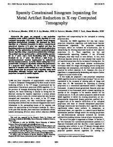
D. Numerical Results We simulate the rate allocation for the proposed group decoder for the relay system with K = 6 sources and destinations. Assume that for 1 ≤ i ≤ 6, the positions of source i and destination i are (−0.5, 0.5 × i) and (0.5, 0.5 × i), respectively. For fixed relay assignment, we assume that there are 6 relays and the position of relay i is (0, 0.5×i) for 1 ≤ i ≤ 6, where each relay i is assigned to assist source i. For dynamic relay assignment, we assume that there are N = 3 relays and the position of relay i is (0, 0.75+0.5×i) for 1 ≤ i ≤ 3. The channel gain between two nodes is assumed to be complex Gaussian distributed with the mean zero and the variance 1/d2 where d is the distance between the two nodes. We assume that the first phase occupies half of the entire transmission period, i.e., t = 0.5, and consider the SNR values, P/σ 2 , from 0dB to 9dB. For each SNR value, 1000 channel realizations are simulated. For the hopping relay system with fixed relay assignment, we plot the minimum rates and sum rates of sources in Fig. 6, respectively, for group decoders with the group size µ denoted as “GD, µ = i” for 1 ≤ i ≤ 3, and for comparison the linear MMSE decoder where all interference is treated as noise. It is seen that the group decoder provides significantly larger minimum and sum rates over the linear MMSE decoder. We also compare the performance of the proposed decode and forward (DF) scheme with the relay amplified and forward (AF) scheme where the group decoder is employed only at the receivers, denoted as “AF + GD”. Since the relays do not decode the source messages and thus superimpose their signals in the second phase, for each channel realization we randomly select a relay to forward the received noisy signals using a scaled power of KP . It is seen that, the proposed DF scheme significantly outperforms the AF scheme for the group sizes µ = 1, 2, and 3, because the AF scheme also forwards the noise to the destinations. Moreover, we tailor the multirelay AF scheme proposed in [15] for a single sourcedestination pair to the multiple source-destination pair scenario using a time-division mode, where each source transmits in the 1/K of the total duration (denoted as “Multi, AF, TDMA”). For fair comparison, each source transmits using power KP and each relay forwards using power P . It is seen that the proposed group decoder significantly outperforms the multi-relay AF scheme. We have also evaluated the performance of the proposed rate allocation scheme for the other three relaying types. Numerical results show that for fixed relay assignment, the minimum rate obtained from the proposed rate allocation scheme significantly outperforms that obtained from the MMSE decoding; and for dynamic relay assignment, the minimum rate obtained from the proposed scheme performs within 90% of the computationally intractable optimal minimum rate obtained from exhaustive search.
JOURNAL OF COMMUNICATIONS, VOL. 7, NO. 5, MAY 2012
0.5
MMSE decoder GD, µ = 1 GD, µ = 2 GD, µ = 3 AF + GD, µ = 1 AF + GD, µ = 2 AF + GD, µ = 3 Multi, AF, TDMA
0.45 0.4 0.35
Min rate
0.3 0.25 0.2 0.15 0.1 0.05 0
0
1
2
3
4
5
6
7
8
9
2
P/σ (dB)
Figure 6. Minimum rates of sources for the hopping relay system
with fixed relay assignment.
VI. C ONCLUSIONS We have provided an overview of the recent development on the group decoding techniques for interference channels. The basic idea is to let each receiver decode, either fully or partially, some interfering signals, in order to optimize the overall system performance, in terms of either total throughput or outage rate. It is seen that for systems that employ fixed-rate coding and modulation, the group decoder can offer significant performance gain over the traditional interference suppression approaches. On the other hand, for systems that employ adaptive coding and modulations, an optimal greedy algorithm can provide both the decoding schedule for each receiver, and the rate allocation for the corresponding transmitter. Practical designs under such group decoding paradigm taking into account practical modulation formats and channel codes have been developed. Moreover, the group decoders also find applications in more sophisticated systems such as relay-assisted interference channels. Compared with the interference alignment approach which performs transmitter side signal processing and requires the channel state information of all users be fedback to the transmitters, the group decoding is a receiver-centric paradigm that not only offers superior performance, but also eliminates the overhead of channel feedback. R EFERENCES [1] V. R. Cadambe and S. A. Jafar, “Interference alignment and degrees of freedom of the K-user interference channel,” IEEE Trans. Info. Theory, vol. 54, no. 8, pp. 3425–3441, Aug. 2008. [2] M. Maddah-Ali, A. Motahari, and A. Khandani, “Communication over MIMO X channels: Interference alignment, decomposition, and performance analysis,” IEEE Trans. Info. Theory, vol. 54, no. 8, pp. 3457–3470, Aug. 2008. © 2012 ACADEMY PUBLISHER
389
[3] R. Tresch, M. Guillaud, and E. Riegler, “On the achievability of interference alignment in the K-user constant MIMO interference channel,” in Statistical Signal Processing, IEEE 15th Workshop on, 31 2009-sept. 3 2009, pp. 277 –280. [4] M. Yamada and T. Ohtsuki, “Interference alignment in the 2 × (1 + N ) MIMO model,” in GLOBECOM Workshops, 2010 IEEE, Dec. 2010, pp. 1963 –1967. [5] K. Gomadam, V. Cadambe, and S. Jafar, “Approaching the capacity of wireless networks through distributed interference alignment,” in Global Telecommunications Conference, 2008, Dec. 2008, pp. 1 –6. [6] H. Yu and Y. Sung, “Least squares approach to joint beam design for interference alignment in multiuser multi-input multi-output interference channels,” IEEE Trans. Signal Process., vol. 58, no. 9, pp. 4960 –4966, Sept. 2010. [7] P. Mohapatra, K. E. Nissar, and C. R. Murthy, “Interference alignment algorithms for the K user constant MIMO interference channel,” IEEE Trans. Signal Process., vol. 59, no. 11, pp. 5499 –5508, Nov. 2011. [8] T. S. Han and K. Kobayashi, “A new achievable rate region for the interference channel,” IEEE Trans. Info. Theory, vol. 27, no. 1, pp. 49 – 60, Jan. 1981. [9] N. Prasad and X. Wang, “Outage minimization and rate allocation for the multiuser Gaussian interference channels with successive group decoding,” IEEE Trans. Info. Theory, vol. 55, no. 12, pp. 5540–5557, Dec. 2009. [10] A. Tajer, N. Prasad, and X. Wang, “Beamforming and rate allocation in MISO cognitive radio networks,” IEEE Trans. Signal Process., vol. 58, no. 1, pp. 362–377, Jan. 2010. [11] A. Motahari and A. Khandani, “To decode the interference or to consider it as noise,” IEEE Trans. Info. Theory, submitted. [12] C. Gong, A. Tajer, and X. Wang, “Interference channel with constrained partial group decoding,” IEEE Trans. Commun., vol. 59, no. 11, pp. 3059 – 3071, Nov 2011. [13] C. Gong, G. Yue, and X. Wang, “Analysis and optimization of a rateless coded joint relay system,” Trans. Wireless Commun., vol. 9, no. 3, pp. 1175–1185, March 2009. [14] C. Gong, A. Tajer, and X. Wang, “Interference channel with constrained partial group decoding,” submitted to IEEE Journal Select. Area Commun. [15] H. Bolcskei, R. U. Nabar, O. Oyman, and A. J. Paulraj, “Capacity scaling laws in MIMO relay networks,” IEEE Trans. Wireless Commun., vol. 5, no. 6, pp. 1433–1444, Jun. 2006.
Chen Gong received the B.S. degree in electrical engineering and mathematics (minor) from Shanghai Jiaotong University, Shanghai, China in 2005, M.S. degree in electrical engineering from Tsinghua University, Beijing, China in 2008. Now he is pursuing his Ph.D degree in Columbia University, New York City, New York, USA. His research interests are in the area of channel coding and modulation techniques for wireless communications.
Omar Abu-Ella received the B.Sc. degree in electrical engineering (with honor) from Academy of Aero Studies and Sciences, Misurata, Libya, in 2001, and his MS.c. degree from the Higher Institute of Industry (HII), Misurata, Libya, in 2007. He is working toward the Professional degree at the Columbia University in the City of New York. Since 2003, he has joined the Department of Electrical Engineering at Misurata University. Also, he has worked as adjunct lecturer assistant at the HII between 2007 and 2008. His current research interests include several topics in wireless Communications and signal processing
390
for Communications.
Xiaodong Wang (S’98-M’98-SM’04-F’08) received the Ph.D degree in Electrical Engineering from Princeton University. He is a Professor of Electrical Engineering at Columbia University in New York. Dr. Wang’s research interests fall in the general areas of computing, signal processing and communications, and has published extensively in these areas. Among his publications is a recent book entitled “Wireless Communication Systems: Advanced Techniques for Signal Reception”, published by Prentice Hall in 2003. His current research interests include wireless communications, statistical signal processing, and genomic signal processing. Dr. Wang received the 1999 NSF CAREER Award, and the 2001 IEEE Communications Society and Information Theory Society Joint Paper Award. He has served as an Associate Editor for the IEEE Transactions on Communications, the IEEE Transactions on Wireless Communications, the IEEE Transactions on Signal Processing, and the IEEE Transactions on Information Theory. He is a Fellow of the IEEE.
Ali Tajer received the B.Sc. and M.Sc. degrees in Electrical Engineering from Sharif University of Technology, Tehran, Iran, in 2002 and 2004, respectively, and the M.Phil. and the Ph.D. degrees in electrical engineering from Columbia University, New York, NY in 2010. He is currently a Postdoctoral Research Associate in the Department of Electrical Engineering, Princeton University, Princeton, NJ, and an Adjunct Assistant Professor in the Department of Electrical Engineering, Columbia University, New York, NY. He spent the summers 2008 and 2009 as a Research Assistant with NEC Laboratories America, Princeton, NJ. His research interests lie in the general areas of network information theory and statistical signal processing with applications in wireless communication.
© 2012 ACADEMY PUBLISHER
JOURNAL OF COMMUNICATIONS, VOL. 7, NO. 5, MAY 2012