Constructing a Unique and Complex Tilt-UpPanel Structure Utilizing 3D CAD and Animation Juan D. Manrique1, Mohamed Al-Hussein2, Avi Telyas3 and Geoff Funston4
Abstract - This paper presents the concept used to construct a complex residential Tilt-Up-Panel structure utilizing 3D-Modeling and animations. The residence is comprised of 108 panels of varying rectangular shapes with "dog legs" and window and door "cutouts" that look like an assembled jigsaw puzzle. The erection and installation procedure calls for a maximum panel-to-panel joint tolerance of 1.27-cm (1/2-in), often in ninety-degree joints of one panel to another. Due to the inherent complexities of the program, the owner, the design and construction team decided to utilize 3D-modeling and animations to experiment with the construction process on the screen before construction in order to avoid potential costly on-site error. In addition, the 3D-Animation is also expected to be used as a training tool to contractors. This paper focuses on describing the methodology used to integrate a crane selection algorithm, a 3Dmodeleing and animation for the selection and utilization of the crane on the construction sites. A crawler crane (Manitowoc-888 with maximum capacity of 230-ton) equipped with a 45.72-m (150-ft) boom length to lift all 108-panels was selected;. Analytical optimization processes were used to decrease the traveling time of the crawler crane, to improve the crane lifting sequence, and to minimize the cost of the panel casting plates. The crane selection process followed the algorithm developed by [1] and [2]; AutoCAD was used as a medium to develop the 3D-Solid objects of the crane, the panels and the site; MS- Solver was used for the optimization of the casting plate size, location of the cast panels and to minimize the crane relocations; and 3D-Studio MAX was used for the animations. The methodology is best described using the case study which is also presented in this paper. Keywords: Complex structure construction, 3D Animations, 3D Visualizations, Layout Optimization, Crane Selection. 1
2
3
4
Master’s Student and Research Assistant at the University of Alberta, Department of Civil & Environmental Engineering, Hole School of Construction 1-080 Markin/CNRL Natural Resources Engineering Facility, Edmonton, Alberta, Canada T6G 2W2. Email address:
[email protected] Assistant Professor at the Department of Civil & Environmental Engineering, Hole School of Construction 3-011 Markin/CNRL Natural Resources Engineering Facility, Edmonton, Alberta, Canada T6G 2W2. Email Address:
[email protected] President of Seaview LLC Corp., General Builder and Contractor, Old Westbury, NY 11568, USA. Email address:
[email protected] Construction Manager, Seaview LLC Corp. Email address:
[email protected] I. INTRODUCTION
Material handling is an important task in the delivery of construction projects, and cranes are the most crucial resource in achieving this task. Selection of type(s), number(s), and location(s) of crane(s) is essential in planning construction operations. Selecting cranes depends greatly on skilled judgment that accounts for a number of technical, and financial factors. Information utilized in this process may include required attachments, manufacturer performance specifications, and loadcapacity charts. At times this information may be incomplete and requires the user to make decisions on job conditions and categories of cranes for a particular situation, leading to unavoidable mistakes and perhaps to costly decisions. To aid practitioners in selection and utilization of cranes, a number of computer applications were developed. Some of these applications used integer programming and optimization techniques [7] or 3D graphics and simulations [8] and [6]. Others were developed for crane selection utilizing
knowledge-based expert systems [4] and [9]. [1 and 2], advanced the knowledge of crane utilization by developing an optimization algorithm, which assists the cranes user with selecting and locating cranes on construction sites utilizing the geometric cranes information stored in a comprehensive cranes database, which was described in [3]. Tilt-Up, on the other hand, is a complex method that uses casting beds on even prepared ground floors for casting walls or panels On-site. The case study documented in this paper demands a high-degree of accuracy in Tilt-Up erected concrete panels. Based on the job requirements and panel weights, the process starts by selecting a crane to lift the casting walls and swing them to a final location. After setting up the panels, bracings and weld plates are used to connect the structure. Depending on the panel shape and weight, strong backs would be needed for a precise lifting. Shape accuracy is extremely important for complex architectural-structural designs, such as the case of the structure presented in this paper, which calls for a maximum panel-to-panel joint tolerance of 1.27-cm (1/2-in), often in ninety-degree joints of one panel to another; this requires an extremely flat casting slab and very precise formwork. In addition, since the exterior face will receive an acid stain treatment, the panels must exhibit very smooth surface finish free of bug holes, voids or other surface irregularities including the colour and texture of the aggregate. Therefore, the contactor must cast all 108-panles at the same time in order to guarantee uniform aggregate texture and colour. One of the advantages of this singular method is that it reduces construction times and is less capital expensive [5]. The pick-up points for each unit depend on the center of
gravity and structural requirements. In all cases, the panel must reach its final strength capacity before being lifted, and then it must rotate on a vertex, perpendicular to the lifting system axis. This paper presents the challenges of this project, which are due to the unique construction method that will be used to complete the structure with the set level of tolerance and accuracy. Since there are no baring walls; the panels will hold each other, therefore, a need for precise equipment utilization can not be ignored. 3D-Animation becomes a valuable tool to simulate and experiment with the construction process on the computer screen to identify potential future problems in order to avoid costly on site errors. The methodology used will be described through the case study.
construction methodology called “Tilt-Up panels” which is based on reinforced concrete panels, cast On-site. The residence is comprised of four Pavilions and other facilities including a Library, Garden House, and a Gallery. Robert Silman Associates, P.C, N.Y, U.S.A., engineered the structure of the facility.
II. PROPOSED METHODOLOGY
The proposed methodology is best described through the evaluation of the case study. The case used involves the construction of a complex architectural design for a residence, NY, U.S.A. as shown in Figures 1 and 2. The proposed methodology follows the concept illustrated in Figure 3, which focuses on the optimization of the layout for the casting beds by contemplating all constraints: site boundaries, casting plate joint-control connections, cracking plate allowances, crane maximum reach/capacities, crane location and maximum ground pressure near the basement walls. In addition, the proposed mythology incorporated a crane selection process, which followed the algorithm developed by [1 and 2], in order to maximize the crane utilization on site, by analyzing different cranes among a variety of picking-placing point scenarios. The main objective was to minimize the traveling distances for the crane by lifting as many panels as possible from the same crane location. As a result, a Manitowoc 888, 230 tones with a 150 ft boom length was the best match. After the two mentioned processes and having all the parameters defined, the next step is to create a 3D animation that shows the final construction process for the Tilt-Up panels.
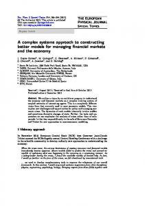
Fig. 2. 3D AutoCAD Model of the case study. It represents the panel phases and groups by colours
This complex project includes 108 tilt-up panels, extending up to 35 ft in length and height with weights ranging from 3,000 lb to 61,000 lb. Most of the panels have a thickness of 8 inches, but some are as thick as 10 inches, as determined by structural requirements. The construction is more than 22,000 square feet in gross area with two upper levels and an underground level.
Fig. 3. Proposed Methodology main process
Fig. 1. The concept model of the case study. This is the 3D Architectural model for the residence III. CASE STUDY
The case study is a unique private residence that is planned for construction at the end of June, 2005. Designed by the Architect Steven Holl, this stunning facility uses an innovative
The livable area is upwards of 18 thousand square feet. The unique structural complexity poses the challenge of optimizing the constructability process. Erecting tilt-up panels is not a widely used technique for residential construction, especially for buildings with panels that have irregular shapes, such as the case presented in this paper, which has 108 panels, and none have the same shape. The form work utilized for their construction could not be reused, because each panel is completely different and the concrete panels also have to be poured in a short period of time for quality purposes and to insure same type of aggregate is used. The other challenges include the crane selection and location, in addition to the establishment of a casting panel layout, which was carried out using an
optimization model. A novel feature of this construction is the introduction of 3D and 4D models to prevent future problems that could arise unexpectedly during the erection of the concrete panels. Knowing all the constraints before tilting up each panel will not only reduce costs, time and labor, but the quality for the installation will more reliably match the expected tolerances. This was carried out in five stages: Stage 1: Crane Selection; during the crane selection stage, an algorithm called “Selectomatic” [1 and 2] produced a list of technically feasible cranes for the tilting-up process. This algorithm has a friendly interface that allows users to specify location constraints (barriers and obstacles surrounding the crane location). It also offers the user an opportunity to update the database to add new cranes. The algorithm was used to select the best crane for this construction. It ranked potential cranes based on their rental cost. Based on the results obtained from this interface, the next step was to choose the crane capable of performing the work while minimizing mobility complications and taking into account operation costs, availability, and accessibility parameters. Based on the last constraints and requirements, and in accordance with the Project Manager and the owner of the construction, the final selection was the Manitowoc 888 (230 tons) with a 150 ft boom length. Stage 2: Crane Mobilization, Picking points, and Casting bed and Panel Layouts; to optimize the processes in the second phase of analysis, an Excel Model was developed to provide a range of possible solutions, and then, based on the location constraints of the construction site, the casting beds and panels were placed in accordance with the crane’s reach and capacity. The input data for the model included panel weights, dimensions, and a 3D model of the house with final panel locations. The weight of the rigging system, including the hooks, slings, spreader bar, and main block was calculated to be 5,000 lb. Several layouts were made, with variable crane displacement and different casting bed shapes. In the end, the constructability issue played the most important roll in defining the layout and the panel location (See Figure 4).
Fig. 4. Site Layout. The casting beds were poured around the construction site. Their sizes range from 12.80m*12.80m to 15.84m*15.84m. Total Area in casting beds: 4316 m2
Stage 3: Building the optimization model in MS-Excel Spreadsheet; the structural design for the case study included a panel installation sequence which could not be modified. The concrete panels were designed to function as a unit; if one piece were to be missing, the structure would be unstable (see Figure 5). The panels’ installation sequence was divided into two main phases. In phase 1, the building was divided into 4 quadrants, each tagged with the letters A, B, C, and D as shown in figure 4. Having a preliminary casting bed area, the first task was to maximize the usage of the crane at its picking locations: in other words, to lift as many panels as possible from each crane position. The second task was to maximize the resource efficiency of the casting beds by reducing the wasted area between the castpanels.
Fig. 5. 3D-View of a Sample of Panels Installation. In this case, the panels will be seated on the blue lines
Fig. 6. Site Final Layout.
The methodology starts with the use of AutoCAD Landscape. This software has the ability to retrieve from a coordinate system the center of mass of each entity—in this
case, the X-Y location of the panels. Importing this data to an Excel spreadsheet, the process continues by making subgroups within each main group. These subgroups contain consecutive panels in the structural sequence. An optimization model using Microsoft Excel Solver was then developed in order to find XY positions for the crane that maximize lifting capacity and minimize crane displacement. The spreadsheet is based on a quadratic optimization model. The Momentum theory was applied to the model satisfying Equation 1, where M defines Momentum; F defines a Force vector (In this case, the panel Weight); and D is the shortest distance from the element’s center of mass to a point of rotation. M = F.d
along the predefined path. At this moment, Solver and Solver Table 1 were applied to obtain the best result. As an example, Table 1 shows the input data and crane final crane location. The X and Y coordinates were iterated in order to determine the min-max momentum. To illustrate the effect, Figure 7 shows the results of altering the crane’s location along the path. Stage 5: Casting bed and Panel Layout; during the layout process, it was important to know the maximum radius at which each panel could be placed from the picking point previously defined. As a constructability issue, the casting beds are made as squared as possible to avoid fractures. If a fracture were to occur, the imperfection would appear on the face of the panel, reducing its aesthetic quality. The casting bed joints provided a panel placement problem. The formwork of the panels could not be positioned across these
(1)
Table 1: Final Crane Location Height (ft)
X (ft)
Y (ft)
Area (SF)
Rigging (Kips)
Panel Weight (Kips)
Total Weight (Kips)
PANEL #
TAG
Width (ft)
Mx
My
21
DW5
27.1
11.8
76.8
42.8
192.1
5
19.21
24.21
1382.2
2054.9
22
DW4
17.4
16.1
76.8
65.1
224.9
5
22.49
27.49
2068.6
2144.6
23
DW3
18.3
29.0
76.8
79.1
423
5
42.3
47.3
4144.9
3630.3
24
DW2
10.3
29.0
76.8
93.4
207.7
5
20.77
25.77
2595.4
2011.8
25
DN2
8.4
29.0
80.6
94.9
233.5
5
23.35
28.35
2938.0
2328.7
26
RW2
23.6
16.3
76.8
107.1
314
5
31.4
36.4
4132.9
2973.8
27
GN1
33.9
7.7
59.7
102.4
161.5
5
22.7
27.7
2894.9
1775.0
28
SCE2
27.2
11.8
44.9
42.8
224.1
5
22.41
27.41
1185.2
1582.1
29
SCE1
19.5
19.6
44.9
66.2
257.5
5
25.7
30.7
2039.5
1434.8
30
GE1
16.3
29.9
44.9
80.0
336.2
5
33.62
38.62
3098.5
1735.1
31
GE2
10.8
15.4
44.9
90.2
167
5
16.7
21.7
1960.8
1003.9
32
GW2
24.6
30.5
29.6
74.8
460
5
46
51
3842.9
1524.8
33
GS1
16.0
30.5
37.2
68.1
362.6
5
36.26
41.26
2810.1
1602.5
34
GW1.1
11.0
4.0
29.6
105.8
44
5
4.4
9.4
998.0
374.4
35
GW1
22.5
30.5
29.6
90.7
388.4
5
38.84
43.84
3997.6
1393.3
36
GN3
20.0
28.8
39.3
102.4
370.7
5
52.1
57.1
5849.8
2608.4
X Y
0 79.1
X pos
39.0
5849.8
3630.3
Y pos
79.1
Min M
3630
FINAL CRANE LOCATION
Stage 4: Crane Mobilization and Picking Points; the objective was to calculate the maximum momentum for each subgroup of panels while varying the crane location along the rectangular path around the house. The model then selects the minimum of the prospective maximum momentums as the most favourable location for the crane. Color code was used to indicate the path that the crane can follow in accordance with the installation sequence as shown in Figure 6. One of the constraints included in the model was the ground pressure exerted on the existing basement walls. The geotechnical Engineer calculated a minimum offset distance from the edge face of the basement to the end of the crane crawlers as 12 ft. Using this information, for each subgroup of panels, the X-Y coordinates where obtained by changing the crane location
joints, and the minimum offset between the edge of the panels and the joints was held in 8 inches while the minimum separation between each panel was 10 inches. Using a spreadsheet again, the boom length was selected according to the capacity provided for the lifting process. The program gave for each boom length the maximum radius for each panel. The best fit for the boom length was in between 150 ft and 180 ft. As the boom length decreases, the capacity is enhanced while the picking radius is lessened. Checking all the maximum radiuses for all the panels, it was decided that the 150 ft boom best suited the 1
Microsoft Excel Solver and Solver table are tools licensed by the Microsoft Corporation 1985-2001.
project. Finally, using the maximum radiuses provided by the 150 ft boom, the layout was drawn using AutoCAD. Problems regarding space were encountered when placing the panels on the casting beds; consequently, the crane has to be moved to perform the lifts. In total, the crane has to travel and sit on 22 different spots, and travel with 3 panels due to the crane capacity, panel layout and placement positions. Momemtum Vs Crane Location 7,000.00
M (Kips.ft
6,000.00 5,000.00 4,000.00
MX
3,000.00
MY
Fig. 9. Proper Lifting
2,000.00 1,000.00 0.00 0
20
40
60
80
100
120
140
Crane Location (ft)
Fig. 7. Momentum Vs. Crane Location IV. CONSTRUCTION ANIMATIONS
During the development of the 3D Animation, potential problems were recognized and addressed accordingly. When a construction is based on tilt-up panels, most of the installed panels require bracings to hold them straight until they are welded together. According to the panel shape, the structural designer had to include strong backs and legs to avoid localized stresses and potential bending and fracturing when the panels are pivoted on their bottom axis (See Figure 8 and 9). For this special case, the 3D and 4D models perform an important job, facilitating reduced constructability issues for the panel lifting, bracing and placement. One requirement of this technique is to pivot the panel from its bottom without dragging it (See Figure 9). To keep the hook-block plump, the crane operator has to realize that the panel has to be tilted up by doing 3 crane movements: swinging the boom, booming up, and hoisting up (See Figure 10).
a)
Connecting the sling to the panel, Plan View
b)
Fig. 8. Panel Configuration
c)
Lifting the panel, Plan View
Erecting and bracing the panel, Plan View
d)
Connecting the slings to the Panel, Perspective View
e)
f)
Lifting the Panel, Perspective View
Erecting and Bracing the panel, Perspective View Fig. 10. 3-D-Animation of Lifting a Panel V. CONCLUSIONS
This paper presented a methodology used to construct a challenging project with a unique construction method that will be used to erect a structure with the necessary level of tolerance and accuracy. Since there are no bearing walls, the panels will hold each other. Therefore, the need for precise equipment utilization can not be ignored. Each of the 108 panels were animated using 3D Studio Max; this software exposed possible constraints, beginning with the tilting up
process for every panel and ending with their final placement. All the requirements for tilting the panels were included in the animation; some of the panels, depending on their shape, structural configuration, and architectural design, had to be tilted-up using 4 different lifting procedures, which were determined by the Designing Engineering firm. Most of the panels are both pivoted and lifted from the face inserts, but some of them have special lifting sequences. These lifting sequences are designated with letters A, B and C. In sequence A, the panel is pivoted to a vertical orientation using the face inserts; after it has been braced to the floor, the temporary legs need to be removed, at which point it can be elevated using the edge inserts. Sequence B is identical only there are no temporary legs remove from the panels. Sequence C panels are pivoted using both type of inserts (face and edge), and are lifted using the top inserts. Then, relevant information is incorporated into the animation to make the tilt-up process as real as possible. During the rotation of each panel, the animation includes the stretching and contraction of slings and the movements of the crane. Although physics is not integrated into the model, the interface is a means to establish the rotation angles that the crane operator can utilize in order to lift the panel in accordance with the predefined specifications. The lifting operation has to be as smooth as possible in order to avoid dragging movements. Based on the optimization model made for this construction project, all the panels were cast in close proximity so as to minimize the expense of the casting beds and the traveling requirements of the crane; as a result, the gaps between most of the panels are narrow which demands accuracy in the tiltup process. The 3D animations reveal which types of movements minimize errors in the tilt-up process. Animating this procedure using 3D Studio Max is useful but time consuming, and improvements can be done in order to improve efficiency. 3D Studio Max includes in its interface a programming tool called MAXScript that allows designers to repeat processes by declaring simple codes. This tool can be used in conjunction with Inverse Kinematics solutions (IK). IK calculates the positions and angles that are needed to target the displacement of objects from their initial to their final position 2 . In this case, the initial position is the crane location with the boom, rigging and slings at a certain instant in a coordinate system, the trajectory delineates the lifting maneuvers, and the final position is the ultimately desired position of the panel. References: [1]
2
Al-Hussein, M., Alkass, S., and Moselhi, O. (2005). “Optimization Algorithm for Selecting and on Site Location of Mobile Cranes” Journal of
Inverse Kinematics Positioning Using Nonlinear Programming for Highly Articulated Figures. ACM Transactions on Graphics 13 (4): 313-316
[2]
[3]
[4]
[5] [6]
[7]
[8]
[9]
Construction Engineering and Management (ASCE), 131 (5), pp. 579-590. Al-Hussein, M., Alkass, S., and Moselhi, O. (2001). “An algorithm for mobile crane selection and location on construction sites.” Construction Innovation Journal, UK, 1:91 – 105. Al-Hussein, M., Alkass, S., and Moselhi, O. (2000). “D-CRANE: Database system for utilization of cranes.” Canadian Journal of Civil Engineering, 27, 1130-1138. Al-Hussein, M. (1999). “An integrated system for crane selection and utilization.” PhD thesis, Department of Building Civil & Environmental Engineering, Concordia University, Montreal, Canada. Meadow Burk, Tampa, FL (2002) “Meadow Burke on Tilt-Up, The complete Tilt-Up System Manual”, Dharwadkar, P. V., Varghese, K., O’Connor, J. T., and Gatton, T. M. (1994). “Graphical visualization for planning heavy lifts.” Proceedings of the 3rd Congress on Computing in Civil Engineering, K. Khozeimeh, ed., ASCE, New York, N. Y., 759-766. Lin, K. L., and Haas, C. T. (1996). “Multiple heavy lifts optimization.” Journal of Construction Engineering and Management, ASCE, 122(4), 354-361. Hornaday, W. C., Haas, C. T., O’Connor, J. T., and Wen, J. (1993). “Computer-aided planning for heavy lifts.” Journal of Construction Engineering and Management, ASCE, 119(3), 498-3515. Zhang P., Harris F. C., Olomolaiye P.O., and Holt G. D. (1999). “Location optimization for a group of tower cranes.” Journal of Construction Engineering and Management, ASCE, 125(2), 115-112