International Journal of Electronics and Electrical Engineering Vol. 3, No. 4, August 2015
Construction of Spin Coating Machine Controlled by Arm Processor for Physical Studies of PVA N. Manikandan Bharathiar University, Coimbatore, India Email:
[email protected]
B. Shanthi and S. Muruganand Karpagam University, Coimbatore, India Bharathiar University, Coimbatore, India Email:
[email protected]
yield, and low cost. A more uniform coating thickness results in reduced coating consumption, greater reproducibility in performance, and interference fringes that are less visible. For spin coating, these interference fringes are less visible since they are in a symmetrical pattern of a few smooth, concentric circles [1].
Abstract—In this paper describes, construction and working of more efficient and compactable spin coating machine with a low power consumption comparing to that of current spin coating machine available in the market. The spin coating machine consists of stepper motor, syringe system, Dc brushless motor and Arm processor. The machine will coat thin film in a micro level thickness and its spinning speed and flow rate of the liquid has been controlled by the arm processor (LPC 11U24). Thickness of the film is determined by the flow rate and coating time of the spinning machine. Films with good uniformity for various thicknesses have been successfully prepared by using above spin coating machine, a capacitor sensor has been fabricated the above spin coating techniques and studied their physical properties
Index Terms—LPC 11U24, motor driver, PVA, spin coater
I.
INTRODUCTION
Nowadays thin film fabrication improves to develop all the applications and in all the fields, which makes up of thin film technology. All the micro level devices, ICs and sensor are fabricated by thin film technology, which is very less in spacious and lower in power consumption of devices. Thin film has been fabricated by many no., of methods like Liquid-Phase Chemical Technique and Chemical Vapour Deposition technique which is the most common method for fabricating thin film. Classification of the methods contains some electro processes such as Mechanical Techniques Electroplating Spray pyrolysis Electroless plating Spray-on techniques Electrolytic anodization Spin-on techniques Chemical reduction plating Chemical displacement plating Electrophoresis deposition Liquid phase epitaxy. The spin coating machine was first described by Emslie et al. (1958) and Meyerhofer et al. (1978) using several simplifications. In this research work construction and design for spin coating machine using ARM processor has been designed, it is one of the unique methods compare to that of other methods, these benefits include more uniform coating thickness, decreased coating consumption, increased Manuscript received January 26, 2014; revised July 21, 2014. ©2015 Engineering and Technology Publishing doi: 10.12720/ijeee.3.4.318-322
318
A. Spin Coating Instrument Model Still spin coating machine has control by PLC and FPGA processor but it quit costly, more or less spin coating machine is controlled by manually, in this research work spin coating machine is full controlled by ARM processor in very low cost, in market so many spin coating machines are available like KW Series, UF82 & LP384036TP, serious 2000S (PLC) based system, these are the some serious machine which has high cost, designed spinning coating machine has too flexible less spacious and it coat thin film in uniform thickness. Using this machine a thin film characteristic can be studied in a various level like concentration, spin speed of this machine etc. B. Film Preparation The step-by-step preparation of a PVA thin film and the process is initiated by making a colloidal suspension, preparing substrates, and spin coating to make a template. The design and cleaning of substrates to prepare them for deposition is also described in, including details of the deposition procedure. The complications and results of depositing PVA under different conditions deals with the formation of samples and the device designed. The structure of a spin coated colloidal template (at different speeds) by spin coating a suspension (prepared in different solvents) is described in terms of thickness variation studies at different speeds [2]. II.
WORKING OF SPIN COATING MACHINE
A. Block Diagram Description The spin coating machine is fully controlled by arm processor, which could be driven by driver circuit to drive a spinning motor [3].
International Journal of Electronics and Electrical Engineering Vol. 3, No. 4, August 2015
There are two thin films of polarizer glued on both sides of the glass. The purpose of the polarizer is to allow the right amount of backlight to pass through it in order to have a proper display. Normally, the digital RPM is using mechanically. Sensor as their element but this project I want to develop using infrared sensor as their element, this special IR sensor is not function as mechanical or other sensor but it is used to detect changing black and white colour, using this concept IR sensor has given as input for ARM LPC11U24 to calculate RPM of collector. The LCD display is connected with arm processor which could be display a speed of the motor, its operating voltage is 5v, LCD contain 8 bit data transfer pins and Rs select pin, R/W(read and write enable ),enable(EN) pin. These are major pins in the LCD, before connect LCD with processor it should be enable the en, Rs, R/W pins. Here two type of data connection is there 8 bit and 4 bit, in this secession LCD has transfer 4bit data transfer from processor. The LCD has been connected with ARM processor.
Each machine requires power supply, power is a major source of all devices. In this machine require 5v for the process operating and 12v for motor driver operating. The motor require 9v for its operating .when the driver is enable motor has been work. Power supply has contained transformer, rectifier, and regulator. All the devices have connection with arm processor, the supply voltage of a processor 5v, a processor enable maximum output voltage is 3.3v, its very low volt, a driver can understand only 5v so that a processor output voltage has been amplified by the amplifier, the processor output is Pulse width modulation depends on PWM output motor speed is control is shown in Fig. 1.
C. Solvent Evaporation Evaporation rate of the solvent for the process it is necessary to have a solvent that evaporates fast at room temperature, like acetone or toluene. The evaporation process influences the flow of the solution. If the evaporation of the solvent is happening very fast, the flow of the solution is going to get slower because of the higher viscosity of the solution. The film thickness depends on the evaporation rate of the solvent [7]. The solvent is not evaporating, this means, the film thickness (d) depends only on the Rotational speed (ω) and spinning time (t).
Figure 1. Block diagram for the spin coating machine
B. Spinner with Motor and Mechanical Setups The automation and controlling are done using ARM LPC11U24 and motor driver L293 [4]. The mechanical rotor is held in the centre soft of the motor axle using chuck. The mechanical rotor can hold the collector plate or glass plate, with respected to motor speed a material has been coated over the glass substrate [5]. The setup consists of ARM Processor, the amplifier circuit, the motor driver, motor with mechanical holding setup. The ARM processor gives controlling output of PWM signal to the motor driver and varies the RPM depends upon the switching frequency. The amplifier is most important part in this machine, because the processor can understand only 3.3 and delivery 3.3v only. But motor driver and other devices can understand only 5v, motor drivers must be enable, and signal pin also 5v. So before give signal to diver must amplify output of the arm processor, for the amplification use MOSFET and npn transistor. The formation of thin film using Spin coating machine needs procedure and steps for uniform thin films on flat substrates. In short, an excess amount of a solution is placed on the substrate, which is then rotated at high speed in order to spread the fluid by centrifugal force [6]. LCD’s are available in various shapes and sizes depending on the configurations. A 16x2 LCD shown in the image below can display 32 characters with 16 characters in each row. It is capable to display any character with ASCII values ranging from 0 to 255.A liquid crystal cell is sandwiched between alignment layers, electrodes, glass plates and polarizer’s. The electrodes are used to apply voltage over the crystals. ©2015 Engineering and Technology Publishing
d = ω-1t-1/2
(1)
The solvent evaporates with a constant rate. d = ω-2/3 (2) The solvent evaporation varies with the square root of the angular velocity. d = ω-1/2
(3)
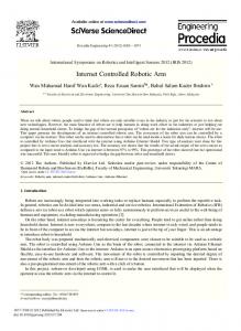
In the spin coating process the interactions between substrate and solution layer are stronger than the interactions between solution surface layer and air. During the spin coating process the solvent evaporates, this leads to an increasing concentration and therefore increasing viscosity, which changes the archeology of the solution. The film thickness is dependent on the viscosity and concentration of the liquid. The more concentrated the solution is, the thicker gets the film. The reverse holds for the dependency of film thickness on angular velocity. Spin Coating. Film thickness against angular velocity by varying concentrations of the solution. The same dependency is obtained for the spinning time. The longer the spinning time is, the smaller gets the film thickness for constant spinning speed [8]. Fig. 2 shows fully constructed spin coating machine. It has a maximum speed of 3000 rpm. First one has to turn on the “air-pressure” left to the left hood (outside). Turn 319
International Journal of Electronics and Electrical Engineering Vol. 3, No. 4, August 2015
maximum intensity diffraction peak at 2θ=19.8o (PVA pdf no 5318-47) corresponding to d spacing 4.4801Å, indicated the presence of a typical semi crystalline structure and the maximum intensity diffraction peak of aluminum at 2θ=44.8 65.3 and 78.4 (85-13-27 pdf no) it consistent with earlier studies. The XRD pattern of the pure PVA has indicated the presence of crystalline behavior, in agreement with the results reported earlier. Fig. 3 is shown below XRD image of PVA thin film [13].
the lever up. Then switch on the vacuum pump in the left hood. The button is next to the spin coater. The spin coater itself does not have to be switched on, this works automatically [9]. Take off the top cover and place the substrate on the middle of the chuck. Close the cover. Press the “start button”. Drop one milliliter of the solution in the beginning rotation of the substrate. When the substrate with the polymer solution is spinning for one minute, press the “stop button” [10].
Intensity (counts)
22500
10000
2500
0 10
20
30
40
50
60
70
80 2Theta (°)
Figure 2. Constructed spin coating machine
III.
Figure 3. XRD of PVA thin film SEM image of PVA
SOFTWARE DESCRIPTION
The processor makes by NXP semiconductor company Mbed as a compiler for programming, this processor work in Keil and mbed compiler. Mbed is a compiler which directly works in internet. This software is user friendly, no require addition library and debug devices. It can understand assembly and c programming. It contains all library inbuilt. While the program has been return, as it is stored in virtual memory. A program is compiled it create bin file is stored into our processor directly to USB. IV.
The thin film surface morphology and functional group of PVA was characterized using scanning electron microscope (SEM). The Fig. 4 shows the SEM images of PVA. The PVA thin film has a large smooth area, indicating formation of transparent film, which has coated by spin coating method and cubic structure has been formed in the coated film, the structure of image has been shown in the Fig. 4 [14], [15].
RESULTS AND DISCUSSION
The constructed spin coating machine has an ability to rotate the substrate uniformly at 1000 rpm, 2000 rpm and 3000 rpm. The PVA solution is prepared by dissolving in the ration of 1:10. The prepared PVA films have been studied for structure, dielectric properties. In the structural analysis XRD and SEM facilities were used. In dielectric characterization in variation of capacitance with frequency (1MHz-5MHz) have been studied. A. Solvent Evaporation Accuracy, sensitivity, reproducibility, are the parameters has been studied for this machine for more than 20 samples has taken, more or less all the samples coated in uniform thickness and a film formed show the capacitance with respected to thickness of film [11]. It used for collect more than one sample at a time, even the machine has quit better reproducing ability for uniform film thickness in this machine [12].
Figure 4. SEM image of spin coated PVA thin film
C. Study of Physical Characteristic of Spin Coated PVA Film The PVA thin film from 10wt% solution concentration has been fabricated in protected environment with the help of zig for removing moisture in the air and impurity
B. Structural Characteristic of PVA XRD of PVA Film The XRD has been taken for spin coated PVA thin films coated over the AL substrate XRD pattern of pure PVA film has been recorded. The observation of the ©2015 Engineering and Technology Publishing
320
International Journal of Electronics and Electrical Engineering Vol. 3, No. 4, August 2015
[16]. First the polymer has dissolved in a solvent, depends on material the solvent has been varied, after the preparing solution has kept over a spinner on electrolytic material, when the machine gets started with respected motor speed and coating timing, the thickness of thin film also get varied [17]. After coating a film its dielectric characteristics has been studied using LCR meter (TH2826). Capacitance reading with respected to frequency as shown. The LCR meter voltage and current are kept as constant 1V and 30mA respectively. Capacitance of the film with the area of 1cm x 1cm as dielectric area is used for study. D or Q: D is called the dissipation factor and is the real part of the impedance divided by the reactance (the imaginary part of the impedance). Q is called the quality factor and is the inverse of D. When D is very small (or Q is large), the component is essentially a pure reactance. Measurement accuracy can be affected by choosing the wrong measurement frequency, measurement model, or trying to measure a part whose value is out of the meter's range. Small capacitors with low dissipation D values are generally easy to measure with the parallel. Increases in frequency gradually increases and decreases suddenly when the quality factor has been decreased because of high frequency [18]. Small capacitors with low dissipation D values are generally easy to measure with the parallel. In the graph capacitance gradually increases of frequency and decreases suddenly at (D=6.03) when the quality factor has been decreased because of high frequency, the graph drawn below Fig. 5 is shows sudden variation, when the ‘D’ factor Increases [19].
flow of spin coating solvent and the spin speed have an influence on the symmetry present in the structure of the spin coated colloidal sample. Hence the constructed spin coating machine can be used to form the thin films with uniformly coated area in low thickness. This spin coating machine is more efficient for different concentration of the solution which can produce good in reproducible, easy to handle and fully automated and lower cost of films. The limitation of this machine is that we can’t increase the rpm more than 3000 because of controlling signal, motor driver and because of motor. The PVA solution of different concentrations has been prepared and the PVA thin films are coated over the Al substrate using the above spin coating machine. Then Al/PVA/Al structure is used for dielectric characteristics. The structural areaof the film is 1cm x 1cm, which is used for dielectric studies. The LCR meter (TH2826) is used for measuring the capacitance of dielectric film. XRD and SEM images of PVA films have been taken, studied and analyzed. XRD shows crystalline nature of the PVA films and SEM shows the cubic nature of the above film. In the dielectric studies the capacitance of the PVA film increases with increase of frequency (1MHz-5MHz) at room temperature. After reaching the 4MHz the capacitance suddenly decreases. The increase of capacitance with increase of frequency up to 3MHz occurs due to the orientation of dipoles. The sudden decrease of capacitance above 3MHz is due to nonorientation of dipoles occurs in the high frequency range in the polymer film. ACKNOWLEDGMENT I express my heart full thanks to DRDO who provide the XRD and SEM facility for this research work and K. Sriram, P. Balakrishna who gave technical support for this work. REFERENCES [1]
[2]
Figure 5. Capacitance responses for frequency
[3] [4]
D. Conclusion The spin coating machine has been constructed using ARM Processor LPC 11U24 and controlling using motor driver L293. The mechanical setup with chuck is designed and tested which holds the rotor axle of the motor. The speed is monitored and controlled by the ARM processor controlling section. The design of spin coating using the ARM Processor gives more precise controlling signals for uniform various controlling speeds from 1000 rpm to 3000 rpm. The samples were prepared by varying two parameters the flow of spin coating solvent and controlling the speed of the substrate. Both
©2015 Engineering and Technology Publishing
[5]
[6] [7]
[8]
[9]
321
T. Maenpaa, “Development of ultra radiation hard silicon particle detector for upgrade of CMS experiment,” University of Helsinki, Finland, Nov. 2008. P. Fontaine, “Sirius: A new multipurpose surface X-ray scattering beam line for study of organic molecular films at French synchrony facility SOLEIL,” University Pierre at Marie Curie PA (012), Oct. 2010. R. frank, Understanding Smart Sensor, Artech House, 2013. N. Raj, “Neural network based closed loop speed control of DC motor using arduino uno,” International Journal of Engineering Trends and Technology, vol. 4, no. 2, 2013. L. George. (Jun. 2012). Interfacing DC motor with PIC microcontroller using L293D. [Online]. Available: http://electrosome.com/dc-motor-l293d-pic-microcontroller/ N. Sahu, “Fundamental understanding and modeling of spin coating process,” Indian J. Phys., vol. 83, no. 4, pp. 493-502, 2009. V. Zaporojtchenko, et al., “Reversible light-induced capacitance switching of azobenzene ether/PMMA blends,” Appl. Phys. A, vol. 102, no. 2, pp. 421-427, 2011. N. K. Shrestha, et al., “Electrophoretic Deposition of phthalocyanine in organic solutions containing trifluoro acetic acid,” American Chemical Society, 2010. K. E. Strawhecker and E. Manias, “Structure and properties of poly (vinyl alcohol)/Na+ montmorillonite nanocomposites,” Chemistry of Materials, vol. 12, no. 10, pp. 2943-2949, 2000.
International Journal of Electronics and Electrical Engineering Vol. 3, No. 4, August 2015
[10] E. P. Giannelis, R. K. Krishnamoorti, and E. Manias, “PolymerSilicate nanocomposites: Model systems for confined polymers and polymer brushes,” Advances in Polymer Science, vol. 138, pp. 107-147, 1999. [11] M. J. O’Connell, Carbon Nanotubes, Taylor & Francis Group, LLC, 2006, pp. 276-281. [12] E. S. M. Sherif, et al., “Coating electrospun polyvinyl alcohol and polyvinyl chloride fibers as corrosion passivation applications,” International Journal of Electrochemical Science, vol. 7, pp. 6154-6167, Jul. 2012 [13] M. A. Reighard and N. A. Barendt, “Advancements in conformal coating process controls,” in Proc. NEPCON WEST, Feb. 2000, pp. 239-248. [14] N. Chand, “Morphology, thermal, electrical and electrochemical stability of nano aluminium-oxide-filled polyvinyl alcohol composite gel electrolyte,” Bulletin of Materials Science, vol. 34, no. 7, pp. 1297-1304, Dec. 2011. [15] B. Eigenmann, V. Schulze, and O. Vöhringer, “Current applications of X-ray diffraction residual stress measurementicrs,” in Proc. ICRS IV, 1994, pp. 598-607. [16] G. A. Luurtsema, “Spin coating for rectangular substrates the department of electrical engineering and computer sciences,” University of California, 1997. [17] M. Froehlich, “Two coating problems: Thin film rupture and spin coating,” Doctoral dissertation, Duke University, 2009. [18] P. S. Prevéy, “Current applications of X-ray diffraction residual stress,” in Developments in Materials Characterization Technologies, G. V. Voort and J. Friel, Eds. 1996, pp. 103-110. [19] M. E. Hilley, Residual Stress Measurement by X-Ray Diffraction, Society of Automotive Engineers, 1980
©2015 Engineering and Technology Publishing
322
B. Shanthi, Research scholar in the Department of physics in Karpagam University She had attended national conference and workshops. Her area of research is the Development of MEMS and NANO electronics. She is presently Research scholar at the Electronics at Karpagam University, she published many research papers in many topics such as: she was present many paper in national conferences and workshops, Thin film, Virtual instrumentation and Biomedical N. Manikandan was born in India in July 1989; He earned his M. Phil in 2013, in Electronics and Instrumentation (Embedded system and MEMS) He received his M.Sc in 2012 in Applied Electronics (Embedded system). He is presently Research scholar at the Electronics and instrumentation Department at Bharathiar University, N. Manikandan published many research papers in many topics such as: Embedded, Thin film and biomedical. He has published 7 international journals and 5 national conferences. He has one year experience in the field of embedded system. Dr. S. Muruganand received the PhD in Physics from Bharathiar University Coimbatore. He is having more than 20 years of experience in Teaching, Research and Industry. His area of research is the development of Nanoelectronics, MEMS/NEMS, Embedded systems and Automation Signal /Image processing Biomedical Instrumentation Thin films.