classes provided by frameworks like Java and .NET, however, is that ..... this neighbor is added to a suspect list, and the philosopher process becomes skeptical.
Container-Based Component Deployment: A Case Study Nigamanth Sridhar, Jason O. Hallstrom, and Paolo A.G. Sivilotti Computer and Information Science The Ohio State University 2015 Neil Ave Columbus OH 43210 USA {nsridhar,hallstro,paolo}@cis.ohio-state.edu
Abstract. A component container, similar to those used to host Enterprise Java Beans, is a runtime environment that manages the execution of components. We have previously described the design and implementation of DRSS, a container architecture for Microsoft’s .NET Framework that provides support for dynamic component deployment. In this paper, we examine the deployment models supported by DRSS, and illustrate their principal advantages in the context of a case study. We describe the evolution of a distributed conflict resolution protocol, with an emphasis on evolving network performance, failure-locality, and visualization support.
1
Introduction
A component container is a runtime environment that manages the execution of components. The container itself can be thought of as a specialized kind of Collection instance, not so dissimilar from the Collections provided by standard class libraries. What distinguishes a component container from the Collection classes provided by frameworks like Java and .NET, however, is that a component container influences the behavior of the components contained within it. Container-hosted components are subject to behavioral transformations that extend the functionality provided by the components in isolation. While a container may impose architectural constraints on the components it hosts, the functionality extensions provided by the container can often be achieved without the hosted components having been explicitly designed to support such extensions. So, for example, a component can be imbued with persistence by virtue of being deployed in its hosting container, without the component having been explicitly designed to support persistence. Perhaps the most well-known example of a component container is the EJB container described in the Enterprise Java Beans specification [15]. Indeed, industry practitioners often use the terms “component container” and “EJB container” interchangeably. An EJB container, however, is just one example of a more abstract concept. Another implementation of this concept is described
2
Sridhar, Hallstrom, and Sivilotti
in [11], which presents the design and implementation of the Dynamic Reconfiguration Sub-System (DRSS) container for Microsoft’s .NET Framework. While similar in spirit to an EJB container, DRSS provides for greater flexibility with respect to component deployment. In this paper we describe the DRSS deployment model, and illustrate the utility of the model in the context of a case study documenting a resource allocation component that we have built for DRSS. We focus on the following deployment advantages offered by DRSS. – Dynamic Component Deployment. DRSS enables the dynamic deployment and removal of container-hosted components, as well as the dynamic substitution of new component implementations. The model provides semantic consistency guarantees that are enforced by our prototype implementation. – Dynamic Service Deployment. DRSS enables the dynamic deployment and removal of cross-cutting container services, allowing the set of containersupplied component extensions to vary at runtime. – Flexible Scoping of Behavioral Transformations. DRSS allows for flexible scoping over the effects of behavioral transformations applied by the container. That is, DRSS allows the designer to easily specify the set of container-hosted components that should be influenced by the deployment of a new container service. Paper Organization. The rest of this paper is organized as follows. We give a brief overview of component containers and some background in the area, along with an introduction to interceptors in Section 2. In Section 3, we outline the deployment model used by DRSS, and some of the advantages of using this deployment model. We illustrate each of these advantages by way of a detailed case study in Section 4, and conclude in Section 5.
2
Component Containers
A component container behaves like a barrier, protecting the enclosed contents from potentially damaging interactions with a harsh environment. In this case, the harsh environment consists of client components that depend on their container-hosted counterparts to implement their operations. Consider, for example, a container that provides authentication and access control to its hosted components. When designing components for such a system, the hosted components will not include support for such security concerns. To do so would be redundant, as those concerns are dispatched by the security services supplied by the container. As a consequence, if a client were to access one of these components directly, outside the container’s purview, security could be compromised. Therefore, container-hosted components must never be accessed directly. All interaction must be mediated by the host. The hosting container is the sole client of each component that it maintains; container-hosted components cannot be aliased. When a client requires access
Container-Based Component Deployment
3
to a component within the container, it must request a reference to the desired component using the container interface. (This is true even if the client component is container-hosted.) In response, the container returns a proxy [9] that appears to the client as the component itself. Invocations on the proxy are marshaled by its underlying implementation, which notifies the container of each invocation request. Each request is intercepted by the container, which eventually performs the requested invocation on behalf of the requesting client. After performing an invocation, the container marshals the results of the invocation (e.g., post-conditional argument values, return values, exceptions), and eventually delivers the marshaled results back to the initiating proxy. Finally, the proxy uses these results to respond to the client as though it were the component itself. The initiating client is unaware of the additional levels of indirection, which are maintained throughout the lifetime of the component. The invocation model, which is markedly similar to that used by commercial middleware implementations like Java RMI [10] and CORBA [18], is illustrated in Figure 1.
Fig. 1. DRSS invocation model
The additional indirection introduced by a component container is not incidental to the architecture. In fact, the additional indirection is precisely what enables the container to transparently transform component functionality. When a component container is notified of an invocation request, it need not deliver the request immediately. Instead, the container can inject additional services in the path of the invocation before it is eventually delivered to the invocation target. It might also inject additional services on the return-trip, before the marshaled response is delivered to the initiating proxy. Although it is somewhat trite, the canonical example of a container-supplied service is invocation logging. By simply recording the marshaled invocation requests it receives, a container can transform the behavior of its hosted components to include support for invocation logging. Of course the underlying implementations of the hosted components are unaffected; the container performs the logging work. From a client’s perspective, however, the hosted components have been transformed. A more complex
4
Sridhar, Hallstrom, and Sivilotti
example is discussed in [17], where the authors use container-based mediation to implement invariant-based state monitoring for an enterprise J2EE application. The additional services supplied by a container can also be modularized as reusable components. These specialized components are termed interceptors, and operate on marshaled invocation requests and responses. In essence, an interceptor is a meta-level entity that transforms the behavior of the components to which it is applied. This meta-level property makes interceptors capable of effecting cross-cutting [16] transformations. Regardless of the functionality they provide, each interceptor supplies an identical interface. Although the actual methods vary from implementation to implementation, conceptually, each interceptor provides one method for processing an invocation request, and another method for processing an invocation response. This interface equivalence makes them easily composable as interceptor chains. An interceptor chain is itself an interceptor, composed of individual interceptors arranged in sequence. When an interceptor chain method is invoked, the chain implementation calls the corresponding method of each interceptor in the underlying sequence. These chain methods are invoked automatically by the container in response to an invocation request or an invocation response. As a result, the container can inject a number of cross-cutting services in the path of component collaborations, without compromising component encapsulation.
3
DRSS-Based Component Deployment
We now turn our attention to the DRSS container, focusing on the two component deployment models that it supports. The first model targets the deployment of application-level components hosted by the container. The second model targets the deployment of interceptor components, which modularize the services the container provides. We restrict our attention to the deployment details, referring the reader to [11] for a full treatment of the DRSS design. 3.1
Dynamic Component Deployment
The DRSS container is realized as a standard class implementation for the .NET Framework. An instance of this class must be declared by every DRSS-based application. As part of its interface, the DRSS container provides management methods for controlling the dynamic deployment and removal of hosted components. This interface is exposed by the container to remote processes, enabling third-party management over the deployment process. When deploying a component, the instance to be hosted is not passed to the container directly. If this were the case, it would be possible for clients to store a reference to the component before it was deployed. After deployment, clients could then bypass the container, thereby bypassing the additional services supplied by the container. Therefore, to deploy a component, the component must be created by the container directly. This is achieved by requiring the client to pass the type information corresponding to the component to be deployed,
Container-Based Component Deployment
5
as well as the arguments to be passed to the component’s constructor. When invoked, this container method constructs an instance of the type passed as argument, and registers the instance under a unique ID that is returned to the client. This ID can later be used to remove the instance from the container, assuming there are no outstanding proxies associated with the instance. The DRSS management interface additionally provides support for dynamic module substitution. That is, the interface provides methods for substituting new component implementations for existing implementations dynamically, without disrupting the services supplied to component clients. The container implements this functionality by temporarily blocking access to the instance to be replaced. If the component being replaced is stateful, the container will then transfer the abstract state of the existing implementation to the new implementation. This is achieved by reflecting on both the new and existing component implementations, to determine whether they both provide the appropriate state transfer functions. In particular, if both components provide a method for serializing their abstract state, as well as a method for de-serializing their abstract state, the container will perform the state transfer automatically. Finally, the container disposes of the existing implementation, and updates its reference table to refer to the new implementation. All future invocation requests destined for the original component instance will now be directed to the new component instance. This implementation leverages work described in [14, 1]. 3.2
Dynamic Service Deployment
In commercial architectures like J2EE, the set of services supplied to containerhosted components is fixed once the container has been initialized. This static deployment precludes the dynamic adaption of the services supplied by the container. So, for example, if increased security risks are detected, it is impossible to deploy additional container-based security services without bringing the container down for maintenance. This is of course an inappropriate strategy for systems with high availability requirements. To overcome this problem, the DRSS container provides methods as part of its management interface for dynamically deploying and removing containersupplied services. This is made possible by the fact that DRSS relies on interceptors to modularize the services that it supplies to hosted components. These interceptors are maintained as chains, and the container interface allows remote processes to manage the interceptors contained in these chains. In particular, given a particular chain, the management interface provides methods for inserting and removing interceptors. 3.3
Flexible Scoping
Commercial container architectures like EJB, and academic container architectures like E”Speak [13], provide support for interceptor composition via interceptor chains. These containers each support only a single interceptor chain that is
6
Sridhar, Hallstrom, and Sivilotti
shared among all container-hosted components. As a consequence, these containers do not provide a mechanism for scoping the effects of interceptor-supplied behavioral transformations. Any change to the interceptor chain results in a behavioral transformation that effects all components hosted by the container. DRSS also supports interceptor composition via interceptor chains. However, the DRSS container provides methods for managing multiple chains. Using the management interface, it is possible, for example, to bind one set of containerhosted components to chain A, and to bind another set of container-hosted components to chain B. Whenever chain A is modified, the resulting behavioral effects will only influence components in the first group. Similarly, changes to chain B will only effect components in the second group. With respect to chain management, the DRSS container provides methods for creating new chains, removing existing chains, binding components to chains, and unbinding components from chains. These methods allow for flexible scoping over the effects of container-supplied behavioral transformations.
4
Case Study: Dining Philosophers
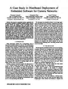
Roadmap. We now present a case study using which we illustrate the aforementioned advantages of the deployment model offered by DRSS. We present a utility component (named Philosopher) that applications deployed into DRSS can use to manage their resource allocation needs. The component uses a solution to the dining philosophers problem as the conflict resolution policy. Further, this component can be used to provide other conflict resolution policies as well through minimal modifications. For example, if the conflict graph were fully connected (the 1-neighborhood of any node describes the entire graph), then the resulting policy is mutual exclusion. We demonstrate dynamic component deployment by first starting an application with one implementation of the Philosopher component — the Asynchronous Doorway implementation [5, 6]. We show some disadvantages of this algorithm in terms of performance, and use dynamic module substitution to replace this implementation with a new one — the Hygienic implementation [3]. Next we show how the failure locality (a measure of the robustness of an algorithm in the presence of faults) of this algorithm can be improved by dynamically deploying a fault localization service. Finally we illustrate how we can dynamically control the scope of services injected into the container architecture by deploying a visualization service to monitor the Philosopher component alone, without affecting the application layer that makes use of the Philosopher component. Problem Specification. The generalized dining philosophers problem can be viewed as a graph in which the nodes represent processes and the edges define the adjacencies between processes (the neighbor relation). This graph is known as the conflict graph. A process in the conflict graph can be either thinking, hungry, or eating; the allowable transitions between these states is shown in Figure 2. Processes eat for a finite amount of time, but may think indefinitely. Processes
Container-Based Component Deployment
7
control their transitions from thinking to hungry and from eating to thinking, while a conflict-resolution layer controls their transitions from hungry to eating.
Fig. 2. States and allowable transitions for dining philosophers
The specification of the dining philosophers problem can be stated as the following two conditions: Safety: No two neighbors eat simultaneously. Progress: Every hungry process is allowed to eat eventually. In this paper, we consider two solutions to the dining philosophers problem, both of which are fork-based — they use forks to ensure safety. A fork is a token that is shared by every two vertices that share an edge. Further, the fork is indivisible and can therefore reside only at one vertex. In order to eat, a process must collect all the forks it shares with its neighbors. This guarantees that no two neighbors eat at the same time, satisfying the safety property above. Implementation 1: The Asynchronous Doorway Algorithm. The asynchronous doorway algorithm1 [5] for dining philosophers uses a fault-tolerant fork collection scheme that uses a pre-emption mechanism based on assigning static priorities to the processes in the conflict graph. A fixed partial ordering is computed by node-coloring the conflict graph. The fork collection scheme is split in two parts; when a process becomes hungry, it first requests and acquires forks from all of its higher-priority neighbors. Once it has acquired all of these forks, the process is said to be at its threshold. Until a process reaches its threshold, any of its neighbors, regardless of priority can pre-empt it by requesting a fork. However, once the process is past its threshold, it is protected from being preempted by its lower-priority neighbors. Higher-priority neighbors can, however, always pre-empt a process at any time, causing it to leave the threshold. Since the priorities of processes is static, some processes will always be able to pre-empt their lower-priority neighbors, thereby thwarting their progress. In order to ensure progress, the algorithm makes use of a doorway that a process has to enter once it reaches its threshold. When a process is inside the doorway, it cannot be pre-empted by any of its neighbors, including its higher-priority neighbors. Moreover, no process can be overtaken more than once in getting into 1
Algorithm 2 as presented in [5]
8
Sridhar, Hallstrom, and Sivilotti
the doorway. The fork-collection scheme, along with the doorway satisfies the progress specification of the dining philosophers problem. We refer the interested reader to [5] for a detailed presentation of this algorithm along with proofs of correctness. One of the reasons we picked this implementation of dining philosophers is because of our long-standing interest in fault-tolerant systems — the algorithm has a low (constant) failure locality of 3. Failure locality is a measure of the robustness of an algorithm in the presence of faults. The m-neighborhood of a process p is defined as the set of processes at most m hops from p. (The 0neighborhood of a process p is just p itself, and its 1-neighborhood is p and its immediate neighbors.) A resource-allocation algorithm is said to have a failure locality of m if a process is not affected by the failure of a process outside its m-neighborhood. However, this implementation of the algorithm was not efficient because it performs poorly in terms of the more commonly used metrics of response time and message complexity. Response time is the delay between a process requesting access to a shared resource and access being granted to that process. Message complexity is the number of messages sent in the system as a result of a single process requesting access to a shared resource. The response time of the asynchronous doorway algorithm is O(δ δ+2 ) and its message complexity is O(δ δ+3 ), where δ is the maximum degree in the conflict graph. Since both these metrics are exponential, we picked a different implementation that improved on these metrics — the hygienic algorithm [4]. The hygienic algorithm for dining philosophers has the advantage of optimal message complexity (O(δ)), and its response time is O(n), where n is the total number of processes in the conflict graph. Implementation 2: The Hygienic Algorithm. The hygienic solution to the dining philosophers problem is a fork-based algorithm based on maintaining a partial order of priority among processes, as shown in Figure 3. That is, the edges of the conflict graph are given directions such that the graph is acyclic. A directed edge in the conflict graph points from a the lower priority neighbor to the higher priority neighbor. A fork held by a higher priority neighbor is said to be clean, while one held by a lower priority neighbor is said to be dirty. In Figure 3, for example, the fork shared between nodes L and J is currently at L, and is dirty, since L has lower priority than J; and the fork shared between nodes L and M is currently at node M and is clean, since M has higher priority than L. When two hungry processes compete for the same fork, the conflict is resolved in favor of the higher-priority process. In other words, a request for a dirty fork is always honored (since such a request came from a higher-priority neighbor), whereas a request for a clean fork is deferred (since the request came from a lower-priority neighbor). As the reader may have observed, these policies only apply when the process receiving a fork request is hungry; if the process were thinking, all requests would immediately be honored, and if it were eating, all requests would be deferred until it finished eating. There is no deadlock because of the acyclicity of a partial order (a “waits-for” cycle cannot form among pro-
Container-Based Component Deployment
9
Fig. 3. Conflict graph showing priorities and partial order in hygienic solution to dining philosophers
cesses). The hygienic algorithm is presented in the form of guarded commands in Figure 4. For a full treatment of the hygienic dining philosophers algorithm, along with a proof of correctness, please see [4].
Become hungry → if hold all forks, begin eating else request all missing forks Receive fork → flip state of fork (clean/dirty) if hold all forks, begin eating
Receive request → if fork is dirty and not eating send fork, and if hungry, re-request else defer request Done eating → all forks become dirty satisfy deferred fork requests
Fig. 4. Original hygienic algorithm (reproduced from [12])
4.1
Dynamic Module Substitution
Now that we have a better implementation of the Philosopher component (in terms of message complexity and response time), how do we allow the application to take advantage of it without having to restart the application? DRSS supports dynamic module substitution — a mode of dynamic reconfiguration that enables the implementation of a component to be changed or “hot-swapped” at run-time. Such substitution is possible in DRSS because any component hosted
10
Sridhar, Hallstrom, and Sivilotti
inside a DRSS platform instance is sitting behind an extra level of indirection. This extra level of indirection decouples a key run time dependency — the dependency between an abstract component interface and the concrete component implementation that is being used by a client program. Since the container architecture controls this extra level of indirection, modifications can be performed to the component instance hosted inside the container without the client ever knowing about them. In order to effect the substitution of the Philosopher implementation, from the asynchronous doorway implementation to the hygienic implementation, we use the strategy detailed in [14]. Of the five stages outlines in that article, Initiation, Module Rebinding, and Instance Rebinding are supported by the DRSS architecture directly [11]. We also use the same techniques for State Migration as those described in [14]. In order to ensure that Module Integrity is respected, we again use the algorithm described in [14]. The DRSS administrator deploys a new (special) Philosopher node, and this node makes itself a neighbor of all nodes in the current conflict graph. In this manner, the administrator node can use the dining philosopher implementation to force quiescence among all other nodes in the conflict graph — for any node to eat, it has to have all of the forks it shares with its neighbors; since the administrator node is a neighbor of every single node in the graph, when it has collected all of its forks, no other node in the entire network can eat. Safety is thus ensured during the process of module substitution. The argument for correctness in terms of progress is detailed in [14]. Dynamic component deployment. The aforementioned steps can be used to hotswap the implementation of the Philosopher utility component without ever having to stop the application layer. In fact, the application layer is not even informed about the change, and is not affected in any way with respect to correctness. The application may, and will most likely, be able to observe a degradation of performance in the dining philosophers layer, but this degradation is transient. This ability to effect dynamic module substitution is afforded by the dynamic component deployment feature of the DRSS container architecture’s deployment model (Section 3.1). 4.2
Fault Localization
We mentioned towards the beginning of the case study that one of the motivations of using the asynchronous doorway implementation of dining philosophers was because of its good failure locality. How does the failure locality of the hygienic algorithm compare? It turns out that although the hygienic algorithm is advantageous in terms of response time and message complexity, it suffers from poor failure locality, since it allows the formation of extremely long dependency chains. The problem is that a process p never yields to a lower-priority neighbor even if p is still missing forks from its higher-priority neighbors. This can lead to a dependency chain, in the worst case, of O(n), where n is the number of processes. The failure locality of this algorithm is therefore d, the diameter of the graph
Container-Based Component Deployment Become hungry → if hold all forks, begin eating else request all missing forks Receive fork → flip state of fork (clean/dirty) if hold all forks, begin eating Receive request → if fork is dirty and not eating send fork and, if hungry, re-request else if skeptical and not eating send fork else defer request
11
Become skeptical → if not eating satisfy deferred fork requests Stop being skeptical → if hungry if hold all forks, begin eating else request all missing forks Done eating → all forks become dirty satisfy deferred fork requests
Fig. 5. Transformed hygienic algorithm (reproduced from [12])
— a single failure anywhere in the network could potentially bring the entire network to a halt. Such bad failure locality is intolerable in our fault-tolerance applications. How do we account for this degradation in failure locality? In [12], Pike and Sivilotti propose a transformation of the hygienic algorithm into one that has a failure locality of 1. This transformation uses an eventually perfect (3P) failure detector [2]. This transformer works in a partially synchronous model, wherein some timing constraints can be enforced, as opposed to an asynchronous model, where no such timing constraints are available owing to the lack of a global clock. This strengthening of the model from pure asynchrony to partial synchrony, however, does not over-simplify the problem since some timing constraints are, in fact, enforceable (to an extent) in real systems [7, 8]. This transformed hygienic algorithm is presented in the form of guarded commands in Figure 5. We use this 3P-based transformation in the DRSS container architecture to provide a fault-containment service to the components deployed in the container. The service is implemented using a set of interceptors, one at each dining philosopher node, that collectively perform the function of the 3P failure detector. Any message that a philosopher node sends or receives is monitored by the interceptor associated with it. Based on the observations that it makes about whether neighbors are alive or crashed, the interceptor may make modifications to the messages; these modifications reduce the failure locality of the hygienic algorithm to 1. The transformation is based on the concept of skepticism. When the failure detector associated with a philosopher thinks that one of its neighbors is crashed, this neighbor is added to a suspect list, and the philosopher process becomes skeptical. At this point, it lowers its priority below all of its neighbors (makes all of its forks dirty), and honors any pending requests. As long as the suspect list is non-empty, the detector associated with this philosopher remains skeptical. A process does not attempt to collect forks while it is skeptical. By staying
12
Sridhar, Hallstrom, and Sivilotti
hungry (and skeptical), this process insulates the rest of the network in case one of its neighbors has crashed while holding a fork. When a process stops being skeptical — as a result of the suspect list becoming empty — it returns to its normal behavior. Please refer to [12] for the proofs of correctness for the transformation, and the transformed algorithm. Dynamic Service Deployment. The failure detector described above is implemented completely outside of the dining philosopher layer. In fact, the Philosopher component is not even aware of the existence of this interceptor. The deployment of the fault localization service is transparent, both to the Philosopher layer and the application layer. The interceptors that make up the service are injected into the interceptor chains for the container platform instance as detailed in Section 3.2. 4.3
Component Visualization
The last service we describe in this paper is a visualization service for the components hosted in the DRSS container architecture. The visualization service for the Philosopher component monitors the entire conflict graph and shows the movement of messages and forks among the philosopher nodes. The visualization service is deployed into one Philosopher node’s container platform instance as the bootstrap mechanism. The service then follows the messages that flow in and out of this platform instance to discover the other nodes that are part of this conflict graph. Every time a new platform is discovered, the discovery process is restarted at that node, looking for its neighbors and so on. In this manner, the service is an eventually perfect stabilizing visualization service. Once all the nodes have been discovered, the service keeps track of the local state of each Philosopher node — thinking, hungry, eating. Any change in (i) the local state of any node, (ii) the location of the forks in the conflict graph, and (iii) the partial order among nodes imposed by their priorities, is shown by graphically modifying the visualization interface. As with the fault localization service, the visualization service is also deployed as a set of interceptors. Each Philosopher node is monitored by an interceptor, and each interceptor is responsible for updating the state of the Philosopher it is associated with, on the visualization interface. Aside from the local state of the node, the interceptor also examines each message passing in or out and updates the status of the forks, and direction of the arrows on the edges between neighboring nodes in the conflict graph. Flexible Scoping. The deployment mechanism for the visualization service is the same as with the fault localization service, except for the scope of application of the service. Rather than deploying the interceptors into all the interceptor chains in a platform instance, they are deployed only into the chains that the Philosopher layer is listening on, and not the other chains. That way, only the Philosopher nodes are visualized, while the application layer (which is also hosted by the same platform instance) is not visualized.
Container-Based Component Deployment
5
13
Conclusions
In this paper, we have described the deployment model provided by the Dynamic Reconfiguration Sub-System (DRSS) — a dynamic, open container architecture built for the Microsoft .NET framework. As opposed to the commerciallyavailable J2EE container architecture, DRSS affords a flexible, and extensible deployment model. The three main advantages of the deployment model are: – Dynamic component deployment, – Dynamic service deployment, and – Flexible scoping of deployed services. We have illustrated these advantages in the context of a detailed case study involving a utility component that provides resource allocation services to applications hosted inside DRSS. We have demonstrated the capabilities of dynamic module substitution, and dynamic deployment of fault-containment and visualization services.
Acknowledgments This work has been supported by the National Science Foundation (NSF) under grant CCR-0081596, by Lucent Technologies and by Microsoft Research. Any opinions, findings, and conclusions or recommendations expressed in this paper are those of the author and do not reflect the views of the NSF, Lucent Technologies, or Microsoft Research. The authors would also like to extend a special note of thanks to Scott Pike for his helpful comments during the implementation of the fault localization service and the writing of this paper.
References 1. M. Castro and B. Liskov. Practical byzantine fault tolerance and proactive recovery. ACM Trans. Comput. Syst., 20(4):398–461, 2002. 2. T. D. Chandra and S. Toueg. Unreliable failure detectors for reliable distributed systems. J. ACM, 43(2):225–267, 1996. 3. K. M. Chandy and J. Misra. The drinking philosophers problem. ACM Trans. Program. Lang. Syst., 6(4):632–646, 1984. 4. K. M. Chandy and J. Misra. Parallel Program Design: A Foundation. AddisonWesley, Reading, MA, USA, 1988. 5. M. Choy and A. K. Singh. Efficient fault tolerant algorithms for resource allocation in distributed systems. In ACM Symposium on Theory of Computing, pages 593– 602, 1992. 6. M. Choy and A. K. Singh. Localizing failures in distributed synchronization:. IEEE Transactions on Parallel and Distributed Systems, 7(7):705–716, 1996. 7. D. Dolev, C. Dwork, and L. Stockmeyer. On the minimal synchronism needed for distributed consensus. J. ACM, 34(1):77–97, 1987.
14
Sridhar, Hallstrom, and Sivilotti
8. C. Dwork, N. Lynch, and L. Stockmeyer. Consensus in the presence of partial synchrony. J. ACM, 35(2):288–323, 1988. 9. E. Gamma, R. Helm, R. Johnson, and J. Vlissides. Design Patterns: Elements of Reusable Object-Oriented Software. Addison Wesley, 1995. 10. W. Grosso. Java RMI. O’Reilly & Associates, 1st edition, 2001. 11. J. O. Hallstrom, W. M. Leal, and A. Arora. Scalable evolution of highly-available systems. IEICE/IEEE Joint Special Issue on Assurance Systems and Networks, May 2003. (to appear). 12. S. M. Pike and P. A. G. Sivilotti. Dining philosophers with crash locality 1. In Proceedings of the 24th IEEE International Conference on Distributed Computing Systems. IEEE, 2004. (to appear). 13. J. Pruyne. Enabling qos via interception in middleware. Technical Report HPL2000-29, HP Laboratories, February 2000. 14. N. Sridhar, S. M. Pike, and B. W. Weide. Dynamic module replacement in distributed protocols. In Proceedings of the 23rd International Conference on Distributed Computing Systems, pages 620–627, May 2003. 15. SunMicrosystems. J2ee 1.3 specification. http://java.sun.com/j2ee/download.html, July 2001. 16. P. Tarr, H. Ossher, W. Harrison, and S. M. Sutton. N degrees of separation: multi-dimensional separation of concerns. In Proceedings of the 21st international conference on Software engineering, pages 107–119. IEEE Computer Society Press, 1999. 17. G. J. Vecellio and W. M. Thomas. Infrastructure support for predictable policy enforcement. In Proceedings of the 6th ICSE Workshop on Component-Based Software Engineering, May 2003. 18. S. Vinoski. Distributed object computing with corba. C++ Report Magazine, 1993.