to the Multipoint Fuel Injection (MPI) system, the engine warning lamp will ...
signal) to take reading of the basic injector drive time and basic ignition timing
from.
13-1
FUEL CONTENTS MULTIPOINT INJECTION (MPI) . . . . . . . 2
ON-VEHICLE SERVICE . . . . . . . . . . . . . . . . 68 Fuel Pump Resistor Check . . . . . . . . . . . . . . . . 68
GENERAL . . . . . . . . . . . . . . . . . . . . . . . . . . . . . . . 2 Outline of Change . . . . . . . . . . . . . . . . . . . . . . . . . 2
Fuel Pump Relay No.2 Continuity Check . . . . . . . . . . . . . . . . . . . . . . . . . 68
SERVICE SPECIFICATIONS . . . . . . . . . . . . . . 4
Engine Control Relay and Fuel Pump Relay Continuity Check . . . . . . . . . . . . . . . . . . . . . . . . . 68
SEALANT . . . . . . . . . . . . . . . . . . . . . . . . . . . . . . . 4
FUEL SUPPLY . . . . . . . . . . . . . . . . . . . . . 69
SPECIAL TOOLS . . . . . . . . . . . . . . . . . . . . . . . . 5 TROUBLESHOOTING . . . . . . . . . . . . . . . . . . . . 6
GENERAL . . . . . . . . . . . . . . . . . . . . . . . . . . . . . 69 Outline of Change . . . . . . . . . . . . . . . . . . . . . . . . 69
FUEL TANK . . . . . . . . . . . . . . . . . . . . . . . . . . . 69
13-2
MPI – General
MULTIPOINT INJECTION (MPI) GENERAL OUTLINE OF CHANGE D D
The descriptions of the troubleshooting using an MUT-II tester have been added. The fuel system and its management of EVOLUTION-VI are different from those of EVOLUTION-V in the following items. Accordingly, the service procedures for these items are described herein. The service procedures for the remaining item are the same as those for EVOLUTION-V. D Fan motor control D Fuel pump drive control D Fuel pump relay No.2 D Fuel pump resistor D Actuator test function of MUT-II (The test of the following items has been made possible.) a) Item No.36: Secondary air control solenoid valve b) Item No.37: Air conditioner condenser fan (High) c) Item No.38: Air conditioner condenser fan (Low)
13-3
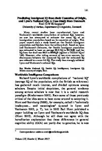
MPI – General MPI System Diagram L1 Oxygen sensor L2 Air flow sensor L3 Intake air temperature sensor L4 Throttle position sensor L5 Idle switch L6 Camshaft position sensor L7 Crank angle sensor L8 Barometric pressure sensor L9 High temperature sensor L10 Engine coolant temperature sensor L11 Detonation sensor D D D D D D D
Engine ECU
Power supply voltage Ignition switch-IG Ignition switch-ST Vehicle speed sensor A/C switch Power steering fluid pressure switch Alternator FR signal
l5
Canister Check valve Secondary air control solenoid valve
From fuel tank
l2
l1 l2 l3 l4 l5
Injector ISC servo Fuel pressure control valve Waste gate solenoid valve Secondary air control solenoid valve
D D D D D D D D D D D
Control relay Fuel pump relay A/C relay Ignition coil Exhaust temperature warning lamp Engine warning lamp Diagnosis output Alternator G terminal Fan motor relay Tachometer Fuel pump relay No.2
ISC servo
Throttle position sensor (with a built-in idle switch)
L4, L5
Secondary air valve
L8 L2
Barometric pressure sensor L3 Intake air temAir flow sensor
To fuel tank L1 Oxygen sensor
Fuel pressure regulator
From fuel pump
Fuel pressure control valve
L6
Camshaft position sensor l1 Injector
perature sensor
Air
l3
L10 Coolant temperature sensor
Waste gate actuator l4
Waste gate solenoid valve
L7 Crank angle sensor L11 Detonation sensor L9 Catalytic converter
High temperature sensor
13-4
MPI – Service Specifications / Sealant
SERVICE SPECIFICATIONS Items
Specifications
Basic ignition timing _BTDC
5±3
Basic idle speed rpm
850 ± 50
Throttle position sensor adjusting voltage mV
400 – 1,000
Throttle position sensor resistance kΩ
3.5 – 6.5
ISC servo coil resistance (at 20_C) Ω
28 – 33
Intake air temperature sensor resistance kΩ
Coolant temperature sensor resistance kΩ
Fuel pressure kPa
At 20_C
2.3 – 3.0
At 80_C
0.30 – 0.42
At 20_C
2.1 – 2.7
At 80_C
0.26 – 0.36
When vacuum hose is connected
230
When vacuum hose is disconnected
289 – 309
Injector coil resistance Ω
2–3
Amount of injector fuel leak drop/min
1 or less
Oxygen sensor output voltage V
0.6 – 1.0
Fuel pressure control valve coil resistance (at 20_C) Ω
28 – 36
SEALANT Item
Specified sealant
Remark
Engine coolant temperature sensor threaded portion
3M Nut Locking Part No.4171 or equivalent
Drying sealant
13-5
MPI – Special Tools
SPECIAL TOOLS Tool
Number
Name
Use
MB991502
MUT-II sub assembly
MPI system inspection
MB991348
Test harness set
D D
Measurement of voltage during troubleshooting Inspection using an oscilloscope
MB991519
Alternator harness connector
Measurement of voltage during troubleshooting
MD998478
Test harness (3-pin, triangle)
D
MB991223
Inspection test harness set D Pin contact pressure inspection harness D Market tester contact probe (for general connectors)
Measurement of terminal voltage
MB991529
Diagnostic trouble code check harness
Reading of diagnosis codes
MB991709
Test harness
D
Red harness
White harness
D
D
Measurement of voltage during troubleshooting Inspection using an oscilloscope
Measurement of voltage during troubleshooting Inspection using an oscilloscope
13-6
MPI – Troubleshooting
TROUBLESHOOTING DIAGNOSIS TROUBLESHOOTING FLOW Refer to GROUP 00 – How to Use Troubleshooting/Inspection Service Points.
DIAGNOSIS FUNCTION ENGINE WARNING LAMP (CHECK ENGINE LAMP) If an abnormality occurs in any of the following items related to the Multipoint Fuel Injection (MPI) system, the engine warning lamp will illuminate. If the lamp remains illuminated or if the lamp illuminates while the engine is running, check the diagnosis code output. Engine warning lamp (check engine lamp)
Engine warning lamp inspection items Engine-ECU Air flow sensor Intake air temperature sensor Throttle position sensor Engine coolant temperature sensor Crank angle sensor Camshaft position sensor Barometric pressure sensor Detonation sensor Injector Ignition coil, power transister unit
METHOD OF READING AND ERASING DIAGNOSIS CODES Refer to GROUP 00 – How to Use Troubleshooting/Inspection Service Points. INSPECTION USING MUT-II DATA LIST AND ACTUATOR TESTING 1. Carry out inspection by connecting the MUT-II. If there is an abnormality, check and repair the chassis harnesses and components. 2. After repairing, check that the abnormal input and output have returned to normal as a result of the repairs. 3. Erase the diagnosis code memory. 4. Remove the MUT-II and carry out a road test to confirm that the problem has disappeared.
MPI – Troubleshooting
13-7
FAIL-SAFE FUNCTION REFERENCE TABLE When the main sensor malfunctions are detected by the diagnosis function, the vehicle is controlled by means of the pre-set control logic to maintain safe conditions for driving. Malfunctioning item
Control contents during malfunction
Air flow sensor
1. 2.
Uses the throttle position sensor signal and engine speed signal (crank angle sensor signal) to take reading of the basic injector drive time and basic ignition timing from the pre-set mapping. Fixes the ISC servo in the appointed position so idle control is not performed.
Intake air temperature sensor
Controls as if the intake air temperature is 25_C.
Throttle position sensor
No increase in fuel injection amount during acceleration due to the throttle position sensor signal.
Engine coolant temperature sensor
1. 2.
Controls as if the engine coolant temperature is 80_C. (This condition is maintained until the ignition switch is turned off even when the sensor signal returns normal.) Lets the fan motor (radiator and condenser) run at high speed.
Camshaft position sensor
Injects fuel to all cylinders simultaneously for 4 seconds. (However, after the ignition switch is turned to ON, the No. 1 cylinder top dead centre is not detected at all.)
Barometric pressure sensor
Controls as if the barometric pressure is 101 kPa.
Detonation sensor
Switches the ignition timing from ignition timing for super petrol to ignition timing for standard petrol.
Ignition coil, transistor unit
Cuts off the fuel supply to cylinders with an abnormal ignition.
power
Alternator FR terminal
Does not control the output of the alternator according to an electrical load. (works as a normal alternator)
13-8
MPI – Troubleshooting
3. INSPECTION CHART FOR DIAGNOSIS CODES Code No.
Diagnosis item
Reference page
12
Air flow sensor system
13-8
13
Intake air temperature sensor system
13-9
14
Throttle position sensor system
13-9
21
Engine coolant temperature sensor system
13-10
22
Crank angle sensor system
13-11
23
Camshaft position sensor system
13-12
24
Vehicle speed sensor system
13-13
25
Barometric pressure sensor system
13-14
31
Detonation sensor system
13-15
41
Injector system
13-15
44
Ignition coil and power transistor unit system
13-16
64
Alternator FR terminal system
13-17
INSPECTION PROCEDURE FOR DIAGNOSIS CODES Code No. 12 Air flow sensor system
Probable cause
Range of Check D Engine speed is 500 r/min or more. Set conditions D Sensor output frequency is 3 Hz or less for 4 seconds.
D Malfunction of the air flow sensor D Improper connector contact, open or short-circuited harness wire of the air flow sensor D Malfunction of the engine-ECU
1. NG Measure at the air flow sensor conCheck the air flow sensor circuit. nector A-25. (Refer to P.13-55, INSPECTION D Connect the connector. (Use PROCEDURE 48.) the test harness: MB991709) 1. Voltage between 3 and earth 2. NG NG (Engine: Idling) Measure at the engine-ECU conOK: 2.2– 3.2 V nector B-59. 2. Voltage between 7 and earth D Connect the connector. OK: 0 – 1 V (Engine: idling) D Voltage between 19 and earth 6 – 9 V (2,000 r/min) (Ignition switch: ON) OK: 6 – 9 V OK Replace the engine-ECU.
Check the following connector: A-25 OK Check trouble symptom. NG
OK NG Check the following connector: B-59 OK Check trouble symptom. NG Replace the engine-ECU.
Repair Replace the air flow sensor.
NG
Repair
13-9
MPI – Troubleshooting Code No. 13 Intake air temperature sensor system
Probable cause
Range of Check D Ignition switch: ON D Excluding 60 seconds after the ignition switch is turned to ON or immediately after the engine starts. Set conditions D Sensor output voltage is 4.6 V or more (corresponding to an intake air temperature of –45_C or less) for 4 seconds. or D Sensor output voltage is 0.2V or less (corresponding to an intake air temperature of 125_C or more) for 4 seconds.
D Malfunction of the intake air temperature sensor D Improper connector contact, open or short-circuited harness wire of the intake air temperature sensor circuit D Malfunction of the engine-ECU
Check the intake air temperature sensor. (Refer to P.13-32.)*
NG
Replace the air flow sensor.
OK Measure at the air flow sensor connector A-25. D Disconnect the connector, and measure at the harness side. D Voltage between 6 and earth (Ignition switch: ON) OK: 4.5– 4.9 V D Continuity between 5 and earth OK: Continuity
NG
Check the following connector: B-62
Check trouble symptom. NG Check the harness wire between the engine-ECU and the intake air temperature sensor connector.
NG
NG Repair
OK
Repair
Replace the engine-ECU.
OK Check trouble symptom.
Repair
OK
OK Check the following connector: A-25
NG
NG
Replace the engine-ECU.
NOTE *: Refer to Workshop Manual for LANCER EVOLUTION-IV and EVOLUTION-V (Pub. No. S9806CNCP9). Code No. 14 Throttle position sensor system
Probable cause
Range of Check D Ignition switch: ON D Excluding 60 seconds after the ignition switch is turned to ON or immediately after the engine starts. Set conditions D The sensor output voltage is 0.2 V or less for 4 seconds.
D Malfunction of the throttle position sensor D Improper connector contact, open or short-circuited harness wire of the throttle position sensor circuit D Improper “ON” state of idle position switch D Short circuit of the idle position switch signal line D Malfunction of the engine-ECU
MUT-II Data list 26 Idle position switch system OK: With the throttle valve at the idle position: ON With the throttle valve slightly open: OFF
NG
Check the idle position switch system. (Refer to P.13-38, INSPECTION PROCEDURE 26.)
OK Check the throttle position sensor.
NG
Replace
OK Measure at the throttle position sensor connector A-16. D Disconnect the connector, and measure at the harness side. D Voltage between 1 and earth (Ignition switch: ON) OK: 4.8– 5.2 V D Continuity between 4 and earth OK: Continuity OK Check the throttle position sensor output circuit. (Refer to P.13-55, INSPECTION PROCEDURE 49.)
NG
Check the following connector: B-62
NG
Repair
OK Check trouble symptom. NG Check the harness wire between the engine-ECU and the throttle position sensor connector. OK Replace the engine-ECU.
NG
Repair
13-10
MPI – Troubleshooting
Code No. 21 Engine coolant temperature sensor system
Probable cause
Range of Check D Ignition switch: ON D Excluding 60 seconds after the ignition switch is turned to ON or immediately after the engine starts. Set conditions D Sensor output voltage is 4.6 V or more (corresponding to an engine coolant temperature of –45_C or less) for 4 seconds. or D Sensor output voltage is 0.1 V or less (corresponding to an engine coolant temperature of 140_C or more) for 4 seconds.
D Malfunction of the engine coolant temperature sensor D Improper connector contact, open or short-circuited harness wire of the engine coolant temperature sensor circuit D Malfunction of the engine-ECU
Range of Check D Ignition switch: ON D Engine speed is approx. 50 r/min or more Set conditions D The sensor output voltage increases from 1.6 V or less (corresponding to an engine coolant temperature of 40_C or more) to 1.6 V or more (corresponding to an engine coolant temperature of 40_C or less). D After this, the sensor output voltage is 1.6 V or more for 5 minutes.
Check the engine coolant temperature sensor. (Refer to P.13-32.)*
NG
Replace
OK Measure at the engine coolant temperature sensor connector A-38. D Disconnect the connector, and measure at the harness side. D Voltage between 1 and earth (Ignition switch: ON) OK: 4.5– 4.9 V D Continuity between 2 and earth OK: Continuity
NG
Check the following connector: B-62
NG
Repair
OK Check trouble symptom. NG Check the harness wire between the engine-ECU and the engine coolant temperature sensor connector.
OK
NG
Repair
OK Replace the engine-ECU.
Check the following connector: A-38 NG Repair
OK
Check trouble symptom. NG Replace the engine-ECU.
NOTE *: Refer to Workshop Manual for LANCER EVOLUTION-IV and EVOLUTION-V (Pub. No. S9806CNCP9).
13-11
MPI – Troubleshooting Code No. 22 Crank angle sensor system
Probable cause
Range of Check D Engine is cranking. Set conditions D Sensor output voltage does not change for 4 seconds (no pulse signal input.)
D Malfunction of the crank angle sensor D Improper connector contact, open or short-circuited harness wire of the crank angle sensor D Malfunction of the engine-ECU
OK Measure at the crank angle sensor connector A-51. D Connect the connector. (Use the test harness: MD998478.) D Voltage between 2 (black clip) and earth (Engine: cranking) OK: 0.4– 4.0 V D Voltage between 2 (black clip) and earth (Engine: idling) OK: 1.5– 2.5 V
Replace the engine-ECU.
NG 1. NG Measure at the crank angle sensor connector A-51. D Disconnect the connector, and measure at the harness side. 1. Voltage between 3 and earth (Ignition switch: ON) 2. NG OK: System voltage 2. Voltage between 2 and earth (Ignition switch: ON) OK: 4.8– 5.2 V 3. NG 3. Continuity between 1 and earth OK: Continuity OK Check the following connector: A-51
Check trouble symptom. NG Replace the crank angle sensor.
Check the following connector: B-62
NG Repair
OK Check trouble symptom. NG
NG
OK
Check the harness wire between the crank angle sensor and the control relay connector, and repair if necessary.
Repair
Check the harness wire between the engine-ECU and the crank angle sensor connector.
NG Repair
OK Replace the engine-ECU.
Check the harness wire between the crank angle sensor and the earth, and repair if necessary.
13-12
MPI – Troubleshooting
Code No. 23 Camshaft position sensor system
Probable cause
Range of Check D Ignition switch: ON D Engine speed is approx. 50 r/min or more. Set conditions D Sensor output voltage does not change for 4 seconds (no pulse signal input.)
D Malfunction of the camshaft position sensor D Improper connector contact, open or short-circuited harness wire of the camshaft position sensor circuit D Malfunction of the engine-ECU
OK Measure at the camshaft position sensor connector A-97. D Connect the connector. D Voltage between 2 and earth (Engine: cranking) OK: 0.4– 3.0 V D Voltage between 2 and earth (Engine: idling) OK: 0.5– 2.0 V
Replace the engine-ECU.
NG 1. NG Measure at the camshaft position sensor connector A-97. D Disconnect the connector, and measure at the harness side. 1. Voltage between 3 and earth (Ignition switch: ON) 2. NG OK: System voltage 2. Voltage between 2 and earth (Ignition switch: ON) OK: 4.8– 5.2 V 3. NG 3. Continuity between 1 and earth OK: Continuity OK Check the following connector: A-97
Check trouble symptom. NG Replace the camshaft position sensor.
Check the following connector: B-62
NG Repair
OK Check trouble symptom. NG
NG
OK
Check the harness wire between the camshaft position sensor and the control relay connector, and repair if necessary.
Repair
Check the harness wire between the engine-ECU and the camshaft position sensor connector.
NG Repair
OK Replace the engine-ECU.
Check the harness wire between the camshaft position sensor and the earth, and repair if necessary.
13-13
MPI – Troubleshooting Code No. 24 Vehicles speed sensor system
Probable cause
Range of check D Ignition switch: ON D Excluding 60 seconds after the ignition switch is turned to ON or immediately after the engine starts. D Idle position switch: OFF D Engine speed is 3,000 r/min or more. D Driving under high engine load conditions. Set conditions D Sensor output voltage does not change for 4 seconds (no pulse signal input).
D Malfunction of the vehicle speed sensor D Improper connector contact, open or short-circuited harness wire of the vehicle speed sensor circuit D Malfunction of the engine-ECU
Check the vehicle speed sensor. (Refer to GROUP 54 – Combination Meters.)
NG
Replace
OK Measure at the vehicle speed sensor connector A-19. D Disconnect the connector, and measure at the harness side. 1. Voltage between 1 and earth (Ignition switch: ON) OK: System voltage 2. Voltage between 3 and earth (Ignition switch: ON) OK: 4.8 – 5.2 V 3. Continuity between 2 and earth OK: Continuity OK NG Check the following connectors: A-19, B-62
Repair
1. NG
2. NG
Check the following connectors: B-64, B-74, B-76
NG
Repair
OK Check trouble symptom.
3. NG
NG NG Check the harness wire between the vehicle speed sensor and ignition switch connector.
Repair
OK
OK
Check the ignition switch. (Refer to GROUP 54 – Ignition Switch.)
Check trouble symptom. NG NG Check the harness wire between the engine-ECU and the vehicle speed sensor connector. OK
Repair
Check the following connector: B-62
NG Repair
OK Check trouble symptom. NG NG
Replace the engine-ECU.
Check the harness wire between the engine-ECU and the vehicle speed sensor connector.
Repair
OK Replace the engine-ECU.
Check the harness wire between the vehicle speed sensor and the earth, and repair if necessary.
13-14
MPI – Troubleshooting
Code No. 25 Barometric pressure sensor system
Probable cause
Range of Check D Ignition switch: ON D Excluding 60 seconds after the ignition switch is turned to ON or immediately after the engine starts. Set conditions D Sensor output voltage is 4.5 V or more (corresponding to a barometric pressure of 114 kPa or more) for 4 seconds. or D Sensor output voltage is 0.2 V or less (corresponding to a barometric pressure of 5.33 kPa or less) for 4 seconds.
D Malfunction of the barometric pressure sensor D Improper connector contact, open or short-circuited harness wire of the barometric pressure sensor circuit D Malfunction of the engine-ECU
Measure at the air flow sensor connector A-25. D Connect the connector. (Use the test harness: MB991709) D Voltage between 2 and earth (Ignition switch: ON) OK: 3.7– 4.3 V (Altitude: 0 m) 3.2– 3.8V (Altitude: 1,200 m)
NG
Measure at the air flow sensor connector A-25. D Disconnect the connector, and measure at the harness side. D Voltage between 1 and earth (Ignition switch: ON) OK: 4.8– 5.2 V D Continuity between 5 and earth OK: Continuity
NG
Check the following connector: A-25
NG Check the harness wire between the engine-ECU and the barometric pressure sensor connector. NG
Check trouble symptom.
OK Repair
Replace the engine-ECU.
NG NG Check the harness wire between the engine-ECU and the baromet- OK ric pressure sensor connector. NG
Check the harness wire between the engine-ECU and the barometric pressure sensor connector, and repair if necessary.
OK Check the following connector: A-25, B-62 OK Check trouble symptom. NG Replace the engine-ECU.
NG
Repair
Repair
Check trouble symptom.
OK
Measure at the engine-ECU connector B-62. D Connect the connector. D Voltage between 85 and earth (Ignition switch: ON) OK: 3.7– 4.3 V (Altitude: 0 m) 3.2– 3.8V (Altitude: 1,200 m)
NG
OK
OK
OK
Check the following connector: B-62
Repair Replace the air flow sensor.
NG
Repair
13-15
MPI – Troubleshooting Code No. 31 Detonation sensor system
Probable cause
Range of Check D Ignition switch: ON D Excluding 60 seconds after the ignition switch is turned to ON or immediately after the engine starts. D Engine speed is approx. 5,000 r/min or more D Set conditions D The change in the detonation sensor output voltage (detonation sensor peak voltage at each 1/2 revolution of the crankshaft) is less than 0.06 V for 200 times in succession.
D Malfunction of the detonation sensor D Improper connector contact, open or short-circuited harness wire of the detonation sensor circuit D Malfunction of the engine-ECU
Measure at the detonation sensor connector A-96. D Disconnect the connector and measure at the harness side. D Continuity between 2 and earth OK: Continuity
OK
NG
Check the following connector: B-62
Repair
OK Check trouble symptom. NG
NG
Check the harness wire between the engine-ECU and the detonation sensor connector.
Check the harness wire between the detonation sensor and earth, and repair if necessary.
OK
Replace the detonation sensor.
Check trouble symptom.
NG
NG
Repair
Replace the engine-ECU.
Code No. 41 Injector system
Probable cause
Range of Check D Engine speed is approx. 50 – 1,000 r/min D The throttle position sensor output voltage is 1.15 V or less. D Actuator test by MUT-II is not carried out. Set conditions D Surge voltage of injector coil is not detected for 4 seconds.
D Malfunction of the injector D Improper connector contact, open or short-circuited harness wire of the injector circuit D Malfunction of the engine-ECU
Check the injector. (Refer to P.13-34.)* Check the resistor. (Refer to P.13-34.)*
NG
Replace
OK Measure at the resistor connector A-125. D Disconnect the connector, and measure at the harness side. D Voltage between 3 and earth (Ignition switch: ON) OK: System voltage
NG
Check the harness wire between the control relay and the resistor connector, and repair if necessary.
OK Measure at the injector connectors A-53, A-54, A-55, A-56 D Disconnect the connector, and measure at the harness side. D Voltage between 1 and earth (Ignition switch: ON) OK: System voltage
NG
NG Check the following connector: A-125
Repair
OK Check trouble symptom.
NG
Check the harness wire between the resistor and the injector connector, and repair if necessary.
OK Check the injector control circuit. (Refer to P.13-55, INSPECTION PROCEDURE 50.)
NOTE *: Refer to Workshop Manual for LANCER EVOLUTION-IV and EVOLUTION-V (Pub. No. S9806CNCP9).
13-16
MPI – Troubleshooting
Code No. 44 Ignition coil and power transistor unit system
Probable cause
Range of Check D Engine speed is approx. 50 – 4,000 r/min D Engine is not cranking. Set conditions D Abnormal rotation due to misfire is detected by crank angle sensor (Either one of coils fails).
D Malfunction of the ignition coil D Improper connector contact, open or short-circuited harness wire of the ignition primary circuit D Malfunction of the engine-ECU
Check the ignition coil. (Refer to GROUP 16 – IGNITION SYSTEM.)
NG
Replace
OK 1. NG Measure at the ignition coil connectors A-110, A-111 D Disconnect the connector, and measure at the harness. 1. Voltage between 1 and earth (Ignition switch: ON) OK: System voltage 2. Voltage between 3 and earth 2. NG (Engine: Cranking) OK: 0.5– 4.0 V 3. Continuity between the 2 and earth 3. NG OK: Continuity
Check the following connectors: B-65, B-76
NG
Check trouble symptom. NG
Check the harness wire between the ignition coil connector and earth, and repair if necessary.
Check the following items. D Check the spark plugs, spark plug cables. D Check the compression pressure.
Repair
OK
Repair
NG
Check the harness wire between the ignition coil and ignition switch connector, and repair if necessary.
Check the following connector: B-59
NG
Check trouble symptom.
NG
Repair
Check the harness wire between the engine-ECU and ignition coil connector.
OK
Check trouble symptom.
NG
OK
Check the following connectors: A-110, A-111
OK
NG Repair
OK
Replace the engine-ECU.
13-17
MPI – Troubleshooting Code No. 64 Alternator FR terminal system
Probable cause
Range of Check D Engine speed is approx. 50 r/min or more Set Conditions D The input voltage from the alternator FR terminal is higher than 4.5 V for 20 seconds.
D Open circuit in alternator FR terminal circuit D Malfunction of the engine-ECU
OK Measure at the alternator connector A-05. D Connect the connector. (Use the test harness: MB991519.) D Voltage between 4 (blue clip) and earth (Engine: Idling) (Radiator fan: Stopped) (Headlamp: OFF → ON) (Brake lamp: OFF → ON) (Rear window defogger switch: OFF → ON) OK: Voltage drops 0.2 to 3.5 V
Replace the engine-ECU.
NG Measure at the alternator connector A-05. D Disconnect the connector, and measure at the harness side. D Voltage between 4 and earth (Ignition switch: ON) OK: 4.8 – 5.2 V
NG
Check the following connectors: B-60, A-88
Check trouble symptom. NG
Check the following connector: A-05
NG Repair
OK
NG Check the harness wire between the engine-ECU and the alternator connector.
Check trouble symptom. NG NG
OK Replace the alternator.
Repair
OK
OK
Check the harness wire between the engine-ECU and the alternator connector.
NG
Repair
OK
Replace the engine-ECU.
Repair
13-18
MPI – Troubleshooting
INSPECTION CHART FOR TROUBLE SYMPTOMS Trouble symptom
Inspection procedure No.
Reference page
Communication with MUT-II is impossible.
Communication with all systems is impossible.
1
13-20
Communication with engine-ECU only is impossible.
2
13-20
Engine warning lamp and related parts
The engine warning lamp does not illuminate right after the ignition switch is turned to the ON position.
3
13-21
The engine warning lamp remains illuminating and never goes out.
4
13-21
No initial combustion (starting impossible)
5
13-22
Initial combustion but no complete combustion (starting impossible)
6
13-23
Long time to start (improper starting)
7
13-24
Unstable idling (Rough idling, hunting)
8
13-25
Idling speed is high. (Improper idling speed)
9
13-26
Idling speed is low. (Improper idling speed)
10
13-27
When the engine is cold, it stalls at idling. (Die out)
11
13-28
When the engine is hot, it stalls at idling. (Die out)
12
13-29
The engine stalls when starting the car. (Pass out)
13
13-30
The engine stalls when decelerating.
14
13-30
Hesitation, sag or stumble
15
13-31
The feeling of impact or vibration when accelerating
16
13-31
The feeling of impact or vibration when decelerating
17
13-32
Poor acceleration
18
13-32
Surge
19
13-33
Knocking
20
13-33
Dieseling
21
13-33
Too high CO and HC concentration when idling
22
13-34
Low alternator output voltage (approx. 12.3 V)
23
13-35
Starting
Idling stability (Improper idling)
Idling stability (Engine stalls)
Driving
13-19
MPI – Troubleshooting PROBLEM SYMPTOMS TABLE (FOR YOUR INFORMATION) Items
Symptom
Starting
Idling stability
Driving
Stopping
Won’t start
The starter is used to crank the engine, but there is no combustion within the cylinders, and the engine won’t start.
Fires up and dies
There is combustion within the cylinders, but then the engine soon stalls.
Hard starting
Engine starts after cranking a while.
Hunting
Engine speed doesn’t remain constant; changes at idle.
Rough idle
Usually, a judgement can be based upon the movement of the tachometer pointer, and the vibration transmitted to the steering wheel, shift lever, body, etc. This is called rough idle.
Incorrect idle speed
The engine doesn’t idle at the usual correct speed.
Engine stall (Die out)
The engine stalls when the foot is taken from the accelerator pedal, regardless of whether the vehicles is moving or not.
Engine stall (Pass out)
The engine stalls when the accelerator pedal is depressed or while it is being used.
Hesitation, Sag
“Hesitation” is the delay in response of the vehicle speed (engine speed) that occurs when the accelerator is depressed in order to accelerate from the speed at which the vehicle is now traveling, or a temporary drop in vehicle speed (engine speed) during such acceleration. Serious hesitation is called “sag”. (Refer to Figure 1.)
Poor acceleration
Poor acceleration is inability to obtain an acceleration corresponding to the degree of throttle opening, even though acceleration is smooth, or the inability to reach maximum speed.
Stumble
Engine speed increase is delayed when the accelerator pedal is initially depressed for acceleration. (Refer to Figure 2.)
Shock
The feeling of a comparatively large impact or vibration when the engine is accelerated or decelerated.
Surge
This is repeated surging ahead during constant speed travel or during variable speed travel.
Knocking
A sharp sound like a hammer striking the cylinder walls during driving and which adversely affects driving.
Run on (“Dieseling”)
The condition in which the engine continues to run after the ignition switch is turned to OFF. Also called “Dieseling”.
(Figure 1)
Hesitation
(Figure 2)
Normal Vehicle speed
Vehicle Initial accelspeed
erator pedal depression
Sag Time
Normal Initial accelerator pedal depression Idling
Stumble Time
13-20
MPI – Troubleshooting
INSPECTION PROCEDURE FOR TROUBLE SYMPTOMS INSPECTION PROCEDURE 1 Communication with MUT-II is impossible. (Communication with all systems is impossible.)
Probable cause
The cause is probably a defect in the power supply system (including earth) for the diagnosis line.
D Malfunction of the diagnosis connector D Malfunction of the harness wire
Measure at the diagnostic connector B-22. D Voltage between 16 and earth OK: System voltage
NG
NG Check the following connectors: B-49, B-75, B-73 B-73, B-80 OK
OK
NG
Check trouble symptom.
Measure at the diagnostic connector B-22. D Continuity between 4 and earth D Continuity between 5 and earth OK: Continuity
Repair
NG
Check the harness wire between the power supply and diagnostic connector, and repair if necessary.
Check the earth wire, and repair if necessary.
OK Replace the MUT-II.
INSPECTION PROCEDURE 2 MUT-II communication with engine-ECU is impossible.
Probable cause
One of the following causes may be suspected. D No power supply to engine-ECU. D Defective earth circuit of engine-ECU. D Defective engine-ECU. D Improper communication line between engine-ECU and MUT-II
D Malfunction of engine-ECU power supply circuit D Malfunction of engine-ECU D Open circuit between immobilizer-ECU and diagnosis connector
Check the following connectors: B-22, B-65, B-32, B-61
NG
Repair
OK Check trouble symptom. NG Check the harness wire between engine-ECU and diagnosis connector. OK Check the engine-ECU power supply and earth circuit. (Refer to P.13-53, INSPECTION PROCEDURE 45.)
NG
Repair
13-21
MPI – Troubleshooting INSPECTION PROCEDURE 3 The engine warning lamp does not illuminate right after the ignition switch is turned to the ON position.
Probable cause
For checking for burnt-out bulb, the engine-ECU causes the engine warning lamp to illuminate for five seconds immediately after the ignition switch is turned to ON. If the engine warning lamp does not illuminate immediately after the ignition switch is turned to ON, one of the malfunctions listed at right has probably occurred.
D Burnt-out bulb of the engine warning lamp D Defective engine warning lamp circuit D Malfunction of the engine-ECU
NG MUT-II Data list 16 engine-ECU power supply voltage (Refer to P.13-57)
Check the engine-ECU power supply and earth circuit. (Refer to P.13-53, INSPECTION PROCEDURE 45.)
OK Measure at the engine-ECU connector B-60. D Disconnect the connector, and measure at the harness side. D Earth the terminal No.36. (Ignition switch: ON) OK: The engine warning lamp illuminates.
OK
Check the following connector: B-60
NG
Repair
OK Check trouble symptom.
NG
NG NG
Replace
Check for burnt-out bulb.
Replace the engine-ECU.
OK NG Measure at the combination meter connector B-08. D Disconnect the connector, and measure at the harness side. D Voltage between 42 and earth (Ignition switch: ON) OK: System voltage
Check the engine warning lamp power supply circuit, and repair if necessary.
OK Check the following connectors: B-08, B-65, B-60
NG
Repair
OK NG Check trouble symptom.
Check the harness wire between combination meter and engineECU connector, and repair if necessary.
INSPECTION PROCEDURE 4 The engine warning lamp remains illuminating and never goes out.
Probable cause
In cases such as the above, the cause is probably that the engine-ECU is detecting a problem in a sensor or actuator, or that one of the malfunctions listed at right has occurred.
D Short-circuit between the engine warning lamp and engine-ECU D Malfunction of the engine-ECU
Yes MUT-II Self-Diag code Are diagnosis codes displayed?
Refer to P.13-8, INSPECTION CHART FOR DIAGNOSIS CODES. No NG
Measure at the combination meter connector B-08. D Disconnect the connector, and measure at the harness side. D Disconnect the engine-ECU connector D Continuity between 53 and earth OK: No continuity OK Replace the engine-ECU.
Check the harness wire between combination meter and engineECU connector, and repair if necessary.
13-22
MPI – Troubleshooting
INSPECTION PROCEDURE 5 No initial combustion (starting impossible)
Probable cause
In cases such as the above, the cause is probably that a spark plug is defective, or that the supply of fuel to the combustion chamber is defective. In addition, foreign materials (water, kerosene, etc.) may be mixed with the fuel.
D D D D D
Malfunction of the ignition system Malfunction of the fuel pump system Malfunction of the injectors Malfunction of the engine-ECU Foreign materials in fuel
NG Check system voltage when cranking. OK: 8 V or higher
Check the battery.
OK MUT-II: Inspection of no initial combustion. (Refer to P.13-47, INSPECTION PROCEDURE 37.) OK NG Can any sound be heard from the injectors when cranking (check using a soundscope)? OK Ignition system: Inspection of no initial combustion. (Refer to P.13-47, INSPECTION PROCEDURE 38.) OK Check the following items. D Check the ignition coil, spark plugs, spark plug cables. D Check if the injectors are clogged. D Check if foreign materials (water, alcohol, etc.) got into fuel. D Check the compression pressure.
Check the injector system. (Refer to P.13-15, INSPECTION PROCEDURE FOR DIAGNOSIS CODE 41.)
13-23
MPI – Troubleshooting INSPECTION PROCEDURE 6 Initial combustion but no complete combustion (starting impossible)
Probable cause
In such cases as the above, the cause is probably that the spark plugs are generating sparks but the sparks are weak, or the initial mixture for starting is not appropriate.
D D D D D
Malfunction of the ignition system Malfunction of the injector system Foreign materials in fuel Poor compression Malfunction of the engine-ECU
NG Check system voltage when cranking. OK: 8 V or higher
Check the battery.
OK MUT-II: Check if uncompleted combustion occurs. (Refer to P.13-48, INSPECTION PROCEDURE 39.) OK NG Can any sound be heard from the injectors when cranking (check using a soundscope)?
Check the injector system, (Refer to P.13-15, INSPECTION PROCEDURE FOR DIAGNOSIS CODE 41.)
OK Is starting good if the engine is cranked with the accelerator pedal slightly depressed?
Yes
Check ISC servo for operation sound.
No OK
NG
Check the ISC servo system. (Refer to P.13-44, INSPECTION PROCEDURE 33.)
D Clean the throttle valve area. D Adjust the fixed SAS. (Refer to P.13-30.)* NG Check the ignition timing when cranking. OK: Approx. 5_BTDC
Check that the crank angle sensor and the timing belt cover are installed properly.
OK Check the following items. D Check the ignition coil, spark plugs, spark plug cables. D Check the injectors for clogging and leakage. D Check the compression pressure. D Check fuel lines for clogging. D Check if foreign materials (water, alcohol, etc.) got into fuel.
NOTE *: Refer to Workshop Manual for LANCER EVOLUTION-IV and EVOLUTION-V (Pub. No. S9806CNCP9).
13-24
MPI – Troubleshooting
INSPECTION PROCEDURE 7 Long time to start (Improper starting)
Probable cause
In cases such as the above, the cause is probably that the spark is weak and ignition is difficult, the initial mixture for starting is not appropriate, or sufficient compression pressure is not being obtained.
D D D D
Malfunction of the ignition system Malfunction of the injector system Inappropriate gasoline use Poor compression
NG Check system voltage when cranking OK: 8 V or higher
Check the battery.
OK MUT-II: Check if uncomplete combustion occurs. (Refer to P.13-48, INSPECTION PROCEDURE 39.) OK NG Can any sound be heard from the injectors when cranking (check using a soundscope)?
Check the injector system. (Refer to P.13-15, INSPECTION PROCEDURE FOR DIAGNOSIS CODE 41.)
OK NG Check the ignition timing when cranking. OK: Approx. 5_BTDC OK Check the following items. D Check the ignition coil, spark plugs, spark plug cables. D Check the injectors for clogging and leakage. D Check the compression pressure. D Check if foreign materials (water, alcohol, etc.) got into fuel.
Check that the crank angle sensor and the timing belt cover are installed properly.
13-25
MPI – Troubleshooting INSPECTION PROCEDURE 8 Unstable idling (Rough idling, hunting)
Probable cause
In cases as the above, the cause is probably that the ignition system, air/fuel mixture, idle speed control (ISC) or compression pressure is defective. Because the range of possible causes is broad, inspection is narrowed down to simple items.
D D D D D D
Malfunction of the ignition system Malfunction of air-fuel ratio control system Malfunction of the ISC servo system Poor compression Drawing air into exhaust system Secondary air backflow to the intake system
Yes Were the battery terminals disconnected recently?
After warming-up, let the engine run at idling for about 10 minutes.
No Yes MUT-II Self-Diag code Are diagnosis codes displayed?
Refer to P.13-8, INSPECTION CHART FOR DIAGNOSIS CODES. No Yes
Does idling speed fluctuate excessively? No NG Check the ISC servo for operation sound. OK NG Check the injector for operation. OK
Check if hunting occurs. (Refer to P.13-48, INSPECTION PROCEDURE 40.) Check the ISC servo system. (Refer to P.13-44, INSPECTION PROCEDURE 33.) Check the injector system. (Refer to P.13-15, INSPECTION PROCEDURE FOR DIAGNOSIS CODE 41.)
MUT-II: Check if idling speed is unstable. (Refer to P.13-49, INSPECTION PROCEDURE 41.) OK NG Check the ignition timing. (Refer to GROUP 11 – Engine Adjustment.)*
Check that the crank angle sensor and the timing belt cover are installed properly.
OK Check the following items. D Check the ignition coil, spark plugs, spark plug cables. D Check the secondary air supply system. (Ensure that there is no back flow of secondary air into the intake system.) D Check the compression pressure. D Check if foreign materials (water, alcohol, etc.) got into fuel.
NOTE *: Refer to Workshop Manual for LANCER EVOLUTION-IV and EVOLUTION-V (Pub. No. S9806CNCP9).
13-26
MPI – Troubleshooting
INSPECTION PROCEDURE 9 Idling speed is high. (Improper idling speed)
Probable cause
In such cases as the above, the cause is probably that the intake air volume during idling is too great.
D Malfunction of the ISC servo system D Malfunction of the throttle body
Yes MUT-II Self-Diag code Are diagnosis codes displayed?
Refer to P.13-8, INSPECTION CHART FOR DIAGNOSIS CODES. No NG
Check the ISC servo for operation sound. OK
Check the ISC servo system. (Refer to P.13-44, INSPECTION PROCEDURE 33.)
NG MUT-II Data list 26 Idle position switch (Refer to P.13-58.)
Check the idle position switch system. (Refer to P.13-38, INSPECTION PROCEDURE 26.)
OK NG MUT-II Data list 21 Engine coolant temperature sensor (Refer to P.13-57.) OK
Check the engine coolant temperature sensor system. (Refer to P.13-10, INSPECTION PROCEDURE FOR DIAGNOSIS CODE 21.)
NG MUT-II Data list 28 A/C switch (Refer to P.13-58.)
Check the A/C switch and A/C relay system. (Refer to P.13-39, INSPECTION PROCEDURE 29.)
OK Basic idle speed adjustment (Refer to P.13-30.)* NG Check trouble symptom.
Clean the throttle valve area.
Adjust the fixed SAS. (Refer to P.13-30.)*
NOTE *: Refer to Workshop Manual for LANCER EVOLUTION-IV and EVOLUTION-V (Pub. No. S9806CNCP9).
MPI – Troubleshooting
13-27
INSPECTION PROCEDURE 10 Idling speed is low. (Improper idling speed)
Probable cause
In cases such as the above, the cause is probably that the intake air volume during idling is too small.
D Malfunction of the ISC servo system D Malfunction of the throttle body
Yes MUT-II Self-Diag code Are diagnosis codes displayed?
Refer to P.13-8, INSPECTION CHART FOR DIAGNOSIS CODES. No NG
Check the ISC servo for operation sound. OK
Check the ISC servo system. (Refer to P.13-44, INSPECTION PROCEDURE 33.)
NG MUT-II Data list 26 Idle position switch (Refer to P.13-58.)
Check the idle position switch system. (Refer to P.13-38, INSPECTION PROCEDURE 26.)
OK NG MUT-II Data list 21 Engine coolant temperature sensor (Refer to P.13-57.) OK
Check the engine coolant temperature sensor system. (Refer to P.13-10, INSPECTION PROCEDURE FOR DIAGNOSIS CODE 21.)
Basic idle speed adjustment (Refer to P.13-30.)* NG Check trouble symptom.
Clean the throttle valve area.
Adjust the fixed SAS. (Refer to P.13-30.)*
NOTE *: Refer to Workshop Manual for LANCER EVOLUTION-IV and EVOLUTION-V (Pub. No. S9806CNCP9).
13-28
MPI – Troubleshooting
INSPECTION PROCEDURE 11 When the engine is cold, it stalls at idling. (Die out)
Probable cause
In such cases as the above, the cause is probably that the air/fuel mixture is inappropriate when the engine is cold, or that the intake air volume is insufficient.
D D D D
Malfunction Malfunction Malfunction Malfunction
of of of of
the the the the
ISC servo system throttle body injector system ignition system
Yes Were the battery terminals disconnected recently?
After warming-up, let the engine run at idling for about 10 minutes.
No Yes MUT-II Self-Diag code Are diagnosis codes displayed?
Refer to P.13-8, INSPECTION CHART FOR DIAGNOSIS CODES. No
Does the engine stall right after the accelerator pedal is released?
Yes
No No Is engine-idling stable after the warming-up? Yes NG Check the ISC servo for operation sound. OK NG Check the injector for operation sound. OK
Clean the throttle valve area.
Adjust the fixed SAS. (Refer to P.13-30.)*
Check for unstable idling (Rough idling, hunting). (Refer to P.13-25, INSPECTION PROCEDURE 8.)
Check the ISC servo system. (Refer to P.13-44, INSPECTION PROCEDURE 33.)
Check the injector system. (Refer to P.13-15, INSPECTION PROCEDURE FOR DIAGNOSIS CODE 41.)
NG MUT-II Data list 26 Idle position switch (Refer to P.13-58.)
Check the idle position switch system. (Refer to P.13-38, INSPECTION PROCEDURE 26.)
OK NG MUT-II Data list 21 Engine coolant temperature sensor (Refer to P.13-57.) OK
Check the engine coolant temperature sensor system. (Refer to P.13-10, INSPECTION PROCEDURE FOR DIAGNOSIS CODE 21.)
Check the fuel pressure. (Refer to P.13-30.)* OK NG Check the ignition timing. (Refer to GROUP 11 – Engine Adjustments.)*
Check that the crank angle sensor and the timing belt cover are installed properly.
OK Check the following items. D Check the ignition coil, spark plugs, spark plug cables. D Check the compression pressure. D Check the engine oil viscosity.
NOTE *: Refer to Workshop Manual for LANCER EVOLUTION-IV and EVOLUTION-V (Pub. No. S9806CNCP9).
13-29
MPI – Troubleshooting INSPECTION PROCEDURE 12 When the engine is hot, it stalls at idling. (Die out)
Probable cause
In such cases as the above, the cause is probably that ignition system, air/fuel mixture, idle speed control (ISC) or compression pressure is defective. In addition, if the engine suddenly stalls, the cause may also be a defective connector contact.
D D D D D D
Malfunction of the ignition system Malfunction of air-fuel ratio control system Malfunction of the ISC servo system Drawing air into intake system Improper connector contact Backflow of secondary air to the intake system
Yes Were the battery terminals disconnected recently?
After warming-up, let the engine run at idling for about 10 minutes.
No Yes MUT-II Diagnosis code Are diagnosis codes displayed?
Refer to P.13-8, INSPECTION CHART FOR DIAGNOSIS CODES. No NG
Check the ISC servo for operation sound. OK NG Check the injector for operation sound. OK Does the engine stall right after the accelerator pedal is released?
Yes
No No Does the engine stall easily again? Yes MUT-II: Engine stalling inspection when the engine is warm and idling. (Refer to P.13-50, INSPECTION PROCEDURE 42.) OK
Check the ISC servo system. (Refer to P.13-44, INSPECTION PROCEDURE 33.)
Check the injector system. (Refer to P.13-15, INSPECTION PROCEDURE FOR DIAGNOSIS CODE 41.)
Clean the throttle valve area.
Adjust the fixed SAS. (Refer to P.13-30.)*
While carrying out an intermittent malfunction simulation test (Refer to GROUP 00 – Points to Note for Intermittent Malfunctions.), check for sudden changes in the signals shown below. D Crank angle sensor signal D Secondary ignition signal D Injector drive signal D Engine-ECU power supply D Fuel pump drive signal voltage D Air flow sensor signal
NG Check the ignition timing. (Refer to GROUP 11 – ENGINE ADJUSTMENTS.)*
Check that the crank angle sensor and the timing belt cover are installed properly.
OK Check the following items. D Check the ignition coil, spark plugs, spark plug cables. D Check the secondary air supply system. (Ensure that there is no backflow of secondary air into the intake system.) D Check if the injectors are clogged. D Check the compression pressure. D Check if foreign materials (water, alcohol, etc.) got into fuel.
NOTE *: Refer to Workshop Manual for LANCER EVOLUTION-IV and EVOLUTION-V (Pub. No. S9806CNCP9).
13-30
MPI – Troubleshooting
INSPECTION PROCEDURE 13 The engine stalls when starting the car. (Pass out)
Probable cause
In cases such as the above, the cause is probably misfiring due to a weak spark, or an inappropriate air/fuel mixture when the accelerator pedal is depressed.
D Drawing air into intake system D Malfunction of the ignition system
Yes MUT-II Self-Diag code Are diagnosis codes displayed?
Refer to P.13-8, INSPECTION CHART FOR DIAGNOSIS CODES. No
Check the following items. D Check the ignition coil, spark plugs, spark plug cables. D Check if air was drawn into the intake system. Broken intake manifold gasket Broken or disconnected vacuum hose Improper operation of the PCV valve Broken air intake hose
INSPECTION PROCEDURE 14 The engine stalls when decelerating.
Probable cause
In cases such as the above, the cause is probably that the intake air volume is insufficient due to a defective idle speed control (ISC) servo system.
D Malfunction of the ISC servo system
Yes Were the battery terminals disconnected recently?
After warming-up, let the engine run at idling for about 10 minutes.
No Yes MUT-II Self-Diag code Are diagnosis codes displayed?
Refer to P.13-8, INSPECTION CHART FOR DIAGNOSIS CODES.
No NG MUT-II Data list 26 Idle position switch (Refer to P.13-58.) P.13-XX.)
Check the idle position switch system. (Refer to P.13-XX, P.13-38, INSPECTION INSPECTION PROCEDURE PROCEDURE 26.) 26.)
OK NG MUT-II Data list 14 Throttle position sensor (Refer to P.13-57.)
Check the throttle position sensor system. (Refer to P.13-9, INSPECTION PROCEDURE FOR DIAGNOSIS CODE 14.)
OK Yes MUT-II Data list 45 ISC servo position D Is the idle speed control (ISC) servo position drops to 0 – 2 steps when decelerating (engine r/min less than 1,000)? No Check the following items. D Check the ignition coil, spark plugs, spark plug cables. D Clean the throttle valve area. D Check and adjust the fixed SAS.
Check the vehicle speed sensor system. (Refer to P.13-13, INSPECTION PROCEDURE FOR DIAGNOSIS CODE 24.)
13-31
MPI – Troubleshooting INSPECTION PROCEDURE 15 Hesitation, sag or stumble
Probable cause
In cases such as the above, the cause is probably that ignition system, air/fuel mixture or compression pressure is defective.
D D D D D D
Malfunction of the ignition system Malfunction of air-fuel ratio control system Malfunction of the fuel supply system Poor compression Malfunction of the turbocharger system Malfunction of the secondary air supply system
Yes MUT-II Self-Diag code Are diagnosis codes displayed?
Refer to P.13-8, INSPECTION CHART FOR DIAGNOSIS CODES. No NG
Check the injectors for operation sound. OK NG Check the ignition timing. (Refer to GROUP 11 – Engine Adjustments.)*
Check the injector system. (Refer to P.13-15, INSPECTION PROCEDURE FOR DIAGNOSIS CODE 41.)
Check that the crank angle sensor and the timing belt cover are installed properly.
OK MUT-II: Check if hesitation, sag, stumble or poor acceleration occurs. (Refer to P.13-51, INSPECTION PROCEDURE 43.) OK Check the fuel pressure. (Refer to P.13-30.)* OK Check the following items. D Check the ignition coil, spark plugs, spark plug cables. D Check the turbocharger boost pressure. D Check the boost pressure control system. D Check the turbocharger turbine wheel for smooth rotation. D Check the compression pressure. D Check the fuel filter or fuel line for clogging. D Check the secondary air supply system.
NOTE *: Refer to Workshop Manual for LANCER EVOLUTION-IV and EVOLUTION-V (Pub. No. S9806CNCP9). INSPECTION PROCEDURE 16 The feeling of impact or vibration when accelerating
Probable cause
In cases such as the above, the cause is probably that there is an ignition leak accompanying the increase in the spark plug demand voltage during acceleration.
D Malfunction of the ignition system
Yes MUT-II Self-Diag code Are diagnosis codes displayed?
Refer to P.13-8, INSPECTION CHART FOR DIAGNOSIS CODES. No
Check the following items. D Check the ignition coil, spark plugs, spark plug cables. D Check for occurrence of ignition leak.
13-32
MPI – Troubleshooting
INSPECTION PROCEDURE 17 The feeling of impact or vibration when decelerating
Probable cause
Malfunction of the ISC servo system is suspected.
D Malfunction of the ISC servo system Yes
MUT-II Self-Diag code Are diagnosis codes displayed?
Refer to P.13-8, INSPECTION CHART FOR DIAGNOSIS CODES. No NG
Check the ISC servo for operation sound. OK NG MUT-II Data list 14 Throttle position sensor (Refer to P.13-57.)
Check the ISC servo system. (Refer to P.13-44, INSPECTION PROCEDURE 33.) Check the throttle position sensor system. (Refer to P.13-9, INSPECTION PROCEDURE FOR DIAGNOSIS CODE 14.)
OK NG MUT-II Data list 26 Idle position switch (Refer to P.13-58.)
Check the idle position switch system. (Refer to P.13-38, INSPECTION PROCEDURE 26.)
OK Clean the throttle valve area.
INSPECTION PROCEDURE 18 Poor acceleration
Probable cause
Defective ignition system, abnormal air-fuel ratio, poor compression pressure, etc. are suspected.
D D D D D D
Malfunction of the ignition system Malfunction of air-fuel ratio control system Malfunction of the fuel supply system Poor compression pressure Clogged exhaust system Malfunction of the turbocharger system
Yes MUT-II Self-Diag code Are diagnosis codes displayed?
Refer to P.13-8, INSPECTION CHART FOR DIAGNOSIS CODES. No NG
Check the injectors for operation sound. OK NG Check the ignition timing. (Refer to GROUP 11 – Engine Adjustments.)*
Check the injector system. (Refer to P.13-15, INSPECTION PROCEDURE FOR DIAGNOSIS CODE 41.)
Check that the crank angle sensor and the timing belt cover are installed properly.
OK MUT-II: Check if hesitation, sag, stumble or poor acceleration occur. (Refer to P.13-51, INSPECTION PROCEDURE 43.) OK Check the fuel pressure. (Refer to P.13-30.)* OK Check the following items. D Check the ignition coil, spark plugs, spark plug cables. D Check the turbocharger boost pressure. D Check the boost pressure control system. D Check the turbocharger turbine wheel for smooth rotation. D Check the compression pressure. D Check the fuel filter or fuel line for clogging. D Broken air intake hose D Clogged air cleaner D Clogged exhaust system
NOTE *: Refer to Workshop Manual for LANCER EVOLUTION-IV and EVOLUTION-V (Pub. No. S9806CNCP9).
MPI – Troubleshooting
13-33
INSPECTION PROCEDURE 19 Surge
Probable cause
Defective ignition system, abnormal air-fuel ratio, etc. are suspected.
D Malfunction of the ignition system D Malfunction of air-fuel ratio control system
Yes MUT-II Self-Diag code Are diagnosis codes displayed?
Refer to P.13-8, INSPECTION CHART FOR DIAGNOSIS CODES. No NG
Check the injectors for operation sound. OK NG Check the ignition timing. (Refer to GROUP 11 – Engine Adjustments.)*
Check the injector system. (Refer to P.13-15, INSPECTION PROCEDURE FOR DIAGNOSIS CODE 41.)
Check that the crank angle sensor and the timing belt cover are installed properly.
OK MUT-II: Check if surge occurs. (Refer to P.13-52, INSPECTION PROCEDURE 44.) OK Check the fuel pressure. (Refer to P.13-30.)* OK Check the following items. D Check the ignition coil, spark plugs, spark plug cables. D Check the waste gate actuator.
NOTE *: Refer to Workshop Manual for LANCER EVOLUTION-IV and EVOLUTION-V (Pub. No. S9806CNCP9). INSPECTION PROCEDURE 20 Knocking
Probable cause
In cases as the above, the cause is probably that the detonation control is defective or the heat value of the spark plug is inappropriate.
D Defective detonation sensor D Inappropriate heat value of the spark plug
Yes MUT-II Self-Diag code Are diagnosis codes displayed?
Refer to P.13-8, INSPECTION CHART FOR DIAGNOSIS CODES. No No
Does knocking occur when driving with the sensor disconnected? At this time, use the MUT-II to check if the timing is retarded compared to when the detonation sensor connector is connected.
Check the detonation sensor system. (Refer to P.13-15, INSPECTION PROCEDURE FOR DIAGNOSIS CODE 31.)
Yes Check the following items. D Spark plugs D Check if foreign materials (water, alcohol, etc.) got into fuel.
INSPECTION PROCEDURE 21 Dieseling
Probable cause
Fuel leakage from injectors is suspected.
D Fuel leakage from injectors
Check the injectors for fuel leakage.
13-34
MPI – Troubleshooting
INSPECTION PROCEDURE 22 Too high CO and HC concentration when idling
Probable cause
Abnormal air-fuel ratio is suspected.
D Malfunction of the air-fuel ratio control system D Deteriorated catalyst Yes
MUT-II Self-Diag code Are diagnosis codes displayed?
Refer to P.13-8, INSPECTION CHART FOR DIAGNOSIS CODES. No NG
Check the ignition timing. (Refer to GROUP 11 – Engine Adjustments.)*
Check that the crank angle sensor and the timing belt cover are installed properly.
OK NG MUT-II Data list 21 Engine coolant temperature sensor. (Refer to P.13-57.) OK NG MUT-II Data list 13 Intake air temperature sensor (Refer to P.13-56.)
Check the engine coolant temperature sensor system. (Refer to P.13-10, INSPECTION PROCEDURE FOR DIAGNOSIS CODE 21.)
Check the intake air temperature sensor system. (Refer to P.13-9, INSPECTION PROCEDURE FOR DIAGNOSIS CODE 13.)
OK NG MUT-II Data list 25 Barometric pressure sensor (Refer to P.13-58.)
Check the barometric pressure sensor system. (Refer to P.13-14, INSPECTION PROCEDURE FOR DIAGNOSIS CODE 25.)
OK NG MUT-II Data list 11 Oxygen sensor OK: 600– 1,000 mV when racing suddenly
Check the oxygen sensor system. (Refer to P.13-15, INSPECTION PROCEDURE FOR DIAGNOSIS CODE 31.)
OK OK MUT-II Data list 11 Oxygen sensor OK: Repeat 0 – 400 mV and 600 – 1,000 mV alternately when idling. NG
Replace the oxygen sensor.
Check trouble symptom. NG
Check the fuel pressure. (Refer to P.13-30.)* OK Check the following items. D Check the injectors for operation sound. D Check the injectors for fuel leakage. D Check the ignition coil, spark plugs, spark plug cables. D Check the compression pressure. D Check the positive crankcase ventilation system. D Check the evaporative emission control system.
Check the trouble symptom. NG Replace the catalytic converter.
NOTE *: Refer to Workshop Manual for LANCER EVOLUTION-IV and EVOLUTION-V (Pub. No. S9806CNCP9).
13-35
MPI – Troubleshooting INSPECTION PROCEDURE 23 Low alternator output voltage (approx. 12.3 V)
Probable cause
The alternator may be defective, or malfunctions, which are listed in the right column, may be suspected.
D Malfunction of charging system D Short circuit in harness between alternator G terminal and engine-ECU D Malfunction of engine-ECU
Measure at the alternator connector side. A-05 D Connect the connector. (Test harness: MB991519) D Voltage between 1 (black clip) and earth Engine: at idle Radiator fan: does not run Headlamp: OFF → ON Brake lamp: OFF → ON Rear defogger switch: OFF → ON OK: Voltages rises by 0.2 – 3.5 V.
NG
Measure at the alternator connector. A-05 D Disconnect the connector, and measure at the harness side. D Disconnect the engine-ECU connector. D Continuity between 1 and earth OK: No continuity
NG
Check the harness wire between the alternator and the engine-ECU connector, and repair if necessary.
OK Check the harness wire between the alternator and the engine-ECU connector.
NG Repair
OK
OK
Replace the engine-ECU.
Check the alternator.
INSPECTION PROCEDURE 24 Power supply system and ignition switch-IG system
Probable cause
When an ignition switch ON signal is input to the engine-ECU, the engine-ECU turns the control relay ON. This causes system voltage to be supplied to the engine-ECU, injectors and air flow sensor.
D Malfunction of the ignition switch D Malfunction of the control relay D Improper connector contact, open or short-circuited harness wire D Disconnected engine-ECU earth wire D Malfunction of the engine-ECU
Check the control relay. (Refer to P.13-68.)
NG
Replace
OK Measure at the control relay connector B-27. D Disconnect the connector, and measure at the harness side. D Voltage between 3, 4 and earth OK: System voltage OK Check the engine-ECU power supply and earth circuit. (Refer to P.13-53, INSPECTION PROCEDURE 45.)
NG
Check the following connector: A-28
NG
Repair
OK Check trouble symptom. NG Check the harness wire between battery and control relay connector, and repair if necessary.
13-36
MPI – Troubleshooting
INSPECTION PROCEDURE 25 Fuel pump system
Probable cause
The engine-ECU turns the control relay ON when the engine is cranking or running, and this supplies power to drive the fuel pump.
D Malfunction of the fuel pump relay D Malfunction of the fuel pump D Improper connector contact, open or short-circuited harness wire D Malfunction of the engine-ECU
NG Check the fuel pump operation by applying the system voltage to the fuel pump drive terminal.
Check the fuel pump circuit. (Refer to P.13-53, INSPECTION PROCEDURE 46.)
OK Check the fuel pump relay. (Refer to P.13-68.)
NG
Replace
OK NG Measure at the fuel pump relay connector B-28. D Connect the connector. D Voltage between 1 and earth D MUT-II Actuator test: Fuel pump drive OK: System voltage
Check the fuel pump drive control circuit. (Refer to P.13-54, INSPECTION PROCEDURE 47.)
OK Check the following connectors: D-18, D-04, B-64, A-124, A-123, B-59, B-60
NG
Repair
OK Check the fuel pump relay No.2. (Refer to P.13-68)
NG
Replace
OK NG Measure at the fuel pump relay No.2 connector A-123. D Disconnect the connector. D Voltage between each of 3 and 5 and earth D MUT-II Actuator test: Fuel pump drive OK: System voltage
Check the harness wire between fuel pump relay and fuel pump relay No.2 connector, and repair if necessary.
OK NG Measure at the engine-ECU connector B-60. D Connect the connector. D Voltage between 39 and earth D MUT-II Actuator test: Fuel pump drive OK: System voltage
Check the harness wire between fuel pump relay No.2 and engine-ECU connector, and repair if necessary.
OK NG Measure at the resistor connector A-124. D Disconnect the connector. D Voltage between 1 and earth D MUT-II Actuator test: Fuel pump relay No.2 drive OK: System voltage
Check the harness wire between fuel pump relay No.2 and resistor connector, and repair if necessary.
OK Check the resistor. (Refer to P.13-34.)*
NG
Replace
OK Check the harness wire between resistor connector and fuel pump drive terminal and between fuel pump relay No.2 connector and fuel pump drive terminal, and repair if necessary.
NOTE *: Refer to Workshop Manual for LANCER EVOLUTION-IV and EVOLUTION-V (Pub. No. S9806CNCP9).
13-37
MPI – Troubleshooting INSPECTION PROCEDURE 25 Fuel pump system
Probable cause
D The engine-ECU turns the fuel pump relay ON when the engine is cranking or running, and this supplies power to drive the fuel pump. D The engine-ECU supplies power to the fuel pump through the resistor at low load operations. It supplies power directly to the fuel pump at high load operations to increase the pump output.
D D D D D
Perform fuel pump operation check. D Disconnect the fuel pump relay No.2 connector. D Apply system voltage to terminal No.2 of the harness side connector. OK: Fuel pump operates.
NG
Malfunction of the fuel pump relay Malfunction of the fuel pump relay No.2 Malfunction of the fuel pump Malfunction of fuel pump resistor Improper connector contact, open or short-circuited harness wire D Malfunction of engine-ECU
Check the fuel pump circuit. (Refer to P.13-54, INSPECTION PROCEDURE 46.)
OK Perform fuel pump operation check. D Disconnect the fuel pump resistor connector. D Apply system voltage to terminal No.2 of the harness side connector. OK: Fuel pump operates.
NG
Check the harness wire between fuel pump resistor and fuel pump connector, and repair if necessary.
OK NG
Check the fuel pump relay. (Refer to P.13-68.)
Replace
OK Check the fuel pump relay No.2 and fuel pump resistor. (Refer to P.13-68.) OK Measure at the fuel pump relay No.2 connector A-123. D Disconnect the connector, and measure at the harness side. D Disconnect the fuel pump resistor connector. D Voltage between each of 1 and 3 and earth D MUT-II Actuator test: 07 Fuel pump drive OK: System voltage
NG
NG
Replace
Check the following connector: B-28
NG
Repair
OK Check trouble symptom. NG
OK
Check the harness wire between fuel pump relay No.2 and fuel pump relay connector, and repair if necessary.
NG
Repair
OK Check the fuel pump drive control circuit. (Refer to P.13-54, INSPECTION PROCEDURE 47.)
Measure at the fuel pump resistor connector A-124. D Disconnect the connector, and measure at the harness side. D Voltage between 1 and earth D MUT-II Actuator test: 13 Fuel pump relay No.2 OK: System voltage
NG
Check the harness wire between fuel pump resistor and fuel pump relay connector, and repair if necessary.
OK Measure at the engine-ECU connector B-60. D Disconnect the connector, and measure at the harness side. D Voltage between 39 and earth D MUT-II Actuator test: 07 Fuel pump OK: System voltage
OK Check trouble symptom. NG Replace the engine-ECU.
Check the following connector: A-123
NG
Repair
OK Check trouble symptom. NG
OK Check the following connector: B-60
NG
NG
Repair
Check the harness wire between fuel pump relay No.2 and engine-ECU connector, and repair if necessary.
13-38
MPI – Troubleshooting
INSPECTION PROCEDURE 26 Idle position switch system
Probable cause
The idle position switch inputs the condition of the accelerator pedal, i.e. whether it is depressed or released (HIGH/LOW), to the engine-ECU. The engine-ECU controls the idle speed control servo based on this input.
D Maladjustment of the accelerator cable D Maladjustment of the fixed SAS D Maladjustment of the idle position switch and throttle position sensor D Improper connector contact, open or short-circuited harness wire D Malfunction of the engine-ECU
NG Check the idle position switch. (Refer to P.13-30.)*
Replace the throttle position sensor.
OK Measure at the throttle position sensor connector A-16. D Disconnect the connector, and measure at the harness side. D Voltage between 3 and earth (Ignition switch: ON) OK: 4 V or higher D Continuity between 4 and earth OK: Continuity
NG
Check the following connector: B-62
NG
Repair
OK Check trouble symptom. NG
OK NG Check the following connector: A-16
Repair
Check the harness wire between engine-ECU and throttle position sensor connector. OK
OK
NG
Replace the engine-ECU.
Check trouble symptom.
Repair
NG Replace the engine-ECU.
NOTE *: Refer to Workshop Manual for LANCER EVOLUTION-IV and EVOLUTION-V (Pub. No. S9806CNCP9). INSPECTION PROCEDURE 27 Ignition switch-ST system
Probable cause
The ignition switch-ST inputs a HIGH signal to the engine-ECU while the engine is cranking. The engine-ECU controls fuel injection, etc. during starting based on this input.
D Malfunction of ignition switch D Improper connector contact, open or short-circuited harness wire D Malfunction of the engine-ECU
1. NG Measure at the engine-ECU connector B-62. D Disconnect the connector, and measure at the harness side. 2. NG 1. Voltage between 71 and earth (Ignition switch: START) OK: 8V 2. Continuity between 91 and earth OK: Continuity OK NG Check the following connector: B-62 OK Check trouble symptom. NG
Check the following connector: B-64
NG Repair
OK Check trouble symptom. NG NG
Repair
Check harness wire between the engine-ECU and ignition switch connector.
Repair
OK Check the ignition switch.
Replace the engine-ECU. Check the harness wire between engine-ECU connector (terminal No.91) and earth, and repair if necessary.
13-39
MPI – Troubleshooting INSPECTION PROCEDURE 28 Power steering fluid pressure switch system
Probable cause
The presence or absence of power steering load is input to the engine-ECU. The engine-ECU controls the idle speed control (ISC) servo based on this input.
D Malfunction of power steering fluid pressure switch D Improper connector contact, open or short-circuited harness wire D Malfunction of the engine-ECU
Check the power steering fluid pressure switch.
NG
Replace
OK Measure at the power steering fluid pressure switch connector A-101. D Disconnect the connector, and measure at the harness side. D Voltage between 1 and earth (Ignition switch: ON) OK: System voltage
NG
Check the following connectors: A-28, B-60
NG
Repair
OK Check trouble symptom.
OK
NG
NG
NG
Repair
Check the following connector: A-101
Check harness wire between engine-ECU and power steering fluid pressure switch connector.
OK Check trouble symptom.
Repair
OK
NG
Replace the engine-ECU.
Replace the engine-ECU.
INSPECTION PROCEDURE 29 A/C switch and A/C relay system
Probable cause
When an A/C ON signal is input to the engine-ECU, the engine-ECU carries out control of the idle speed control (ISC) servo, and also operates the A/C compressor magnetic clutch.
D Malfunction of A/C control system D Malfunction of A/C switch D Improper connector contact, open or short-circuited harness wire D Malfunction of the engine-ECU
Check the A/C compressor relay. (Refer to GROUP 55 – On-vehicle Service.)
NG
Replace
OK NG Measure at the engine-ECU connectors B-59, B-60. D Disconnect the connector, and measure at the harness side. D Voltage between 22 and earth, and 45 and earth (Ignition switch: ON, A/C switch: ON) OK OK: System voltage D Short-circuit between 22 and earth (Ignition switch: ON, A/C switch: ON) OK: A/C compressor clutch turns on.
Check the A/C system. (Refer to GROUP 55 – On-vehicle Service.)
Check the following connectors: B-59, B-60 OK Check trouble symptom. NG Replace the engine-ECU.
NG
Replace
13-40
MPI – Troubleshooting
INSPECTION PROCEDURE 30 Fan motor relay system (Radiator fan, A/C condenser fan)
Probable cause
The engine-ECU turns on/off the built-in power transistor to control the fan motor relay.
D Malfunction of the fan motor relay D Malfunction of the fan motor D Improper connector contact, open or short-circuited harness wire D Malfunction of engine-ECU
Measure at the engine-ECU connector B-59. D Disconnect the connector, and measure at the harness side. D Voltage between each of 20 and 21 and earth (Ignition switch: ON) OK: System voltage D Short the terminal 21 to earth. (Ignition switch: ON) OK: Fan operates at low speed. D Short the terminals 20 and 21 to earth. (Ignition switch: ON) OK: Fan operates at high speed. NG D Check the radiator fan circuit. D Check the A/C condenser fan circuit. (Refer to Electrical Wirings.)
OK
Check the following connector: B-59 OK Check trouble symptom. NG Replace the engine-ECU.
NG
Repair
13-41
MPI – Troubleshooting INSPECTION PROCEDURE 30 Fan motor relay system (Radiator fan, A/C condenser fan)
Probable cause
The engine-ECU turns on/off the built-in power transistor to control the fan motor relay.
D D D D
Measure at the engine-ECU connector B-59. D Disconnect the connector, and measure at the harness side. D Check the radiator fan for operating condition. (Ignition switch: ON) OK: Radiator fan is stationary. D Voltage between each of 20 and 21 and earth (Ignition switch: ON) OK: System voltage D Short the terminal 20 to earth. (Ignition switch: ON) OK: Radiator fan operates at high speed. D Short the terminal 21 to earth. (Ignition switch: ON) OK: Radiator fan operates at low speed.
NG
Malfunction of the fan motor relay Malfunction of the fan motor Malfunction of thermostat Improper connector contact, open or short-circuited harness wire D Malfunction of engine-ECU
Check the radiator fan circuit. (Refer to Electrical Wirings.)
OK Check the following connector: B-59
NG
Repair
OK Check trouble symptom. NG Measure at the engine-ECU connector B-60. D Disconnect the connector, and measure at the harness side. D Check the A/C condenser fan for operating condition. (Ignition switch: ON) OK: A/C condenser fan is stationary. D Voltage between each of 32 and 34 and earth (Ignition switch: ON) OK: System voltage D Short the terminal 32 to earth. (Ignition switch: ON) OK: A/C condenser fan operates at high speed. D Short the terminal 34 to earth. (Ignition switch: ON) OK: A/C condenser fan operates at low speed.
NG
Check the A/C condenser fan circuit. (Refer to Electrical Wirings.)
OK Check the following connector: B-60
NG
Repair
OK Check trouble symptom. NG MUT-II Data list 21 Engine coolant temperature sensor OK: The engine coolant temperature agrees with the reading of MUT-II when measured with the engine idling in warm condition. NG Check the engine coolant temperature sensor. (Refer to P.13-10, INSPECTION PROCEDURE FOR DIAGNOSIS CODE 21.)
OK
Check the thermostat. OK Replace the engine-ECU.
NG
Replace
13-42
MPI – Troubleshooting
INSPECTION PROCEDURE 31 Oxygen sensor system
Probable cause
When CO or HC concentration is too high, the malfunction of the parts shown at right may be the cause. D The oxygen sensor detects the density of oxygen in exhaust gas and inputs it to the engine-ECU after converting into a voltage signal. D The engine-ECU controls the fuel injection amount based on this signal such that the stoichiometric air/fuel mixture ratio can be obtained.
D Malfunction of oxygen sensor D Improper connector contact, open or short-circuited harness wire D Malfunction of engine-ECU
NG
Check the oxygen sensor. (Refer to P.13-32.)*
Replace
OK Measure at the oxygen sensor connector A-63. D Disconnect the connector, and measure at the harness side. D Continuity between 2 and earth OK: Continuity OK Check the following connector: A-63
NG
NG
Check the following connector: B-62
NG
Repair
OK Check trouble symptom. NG
Repair
OK
Check the harness wire between engine-ECU and oxygen sensor connector.
NG
Repair
OK
Check trouble symptom. NG Check the harness wire between engine-ECU and oxygen sensor connector.
Replace the engine-ECU. NG
Repair
OK Replace the engine-ECU.
NOTE *: Refer to Workshop Manual for LANCER EVOLUTION-IV and EVOLUTION-V (Pub. No. S9806CNCP9).
13-43
MPI – Troubleshooting INSPECTION PROCEDURE 31 Oxygen sensor system
Probable cause
When CO or HC concentration is too high, the malfunction of the parts shown at right may be the cause. D The oxygen sensor detects the density of oxygen in exhaust gas and inputs it to the engine-ECU after converting into a voltage signal. D The engine-ECU controls the fuel injection amount based on this signal such that the stoichiometric air/fuel mixture ratio can be obtained.
D Malfunction of oxygen sensor D Improper connector contact, open or short-circuited harness wire D Malfunction of engine-ECU
NG
Check the oxygen sensor. (Refer to P.13-32)*
Replace
OK 1. NG Measure at the oxygen sensor connector A-63. D Disconnect the connector, and measure at the harness side. 1. Voltage between 1 and earth (Ignition switch: ON) 2. NG OK: System voltage 2. Continuity between 2 and earth OK: Continuity OK
Check the harness wire between oxygen sensor and control relay, and repair if necessary.
Check the following connector: B-62
NG
Repair
OK Check trouble symptom. NG Check the harness wire between oxygen sensor, engine-ECU, and repair if necessary.
Measure at the engine-ECU connector B-61. D Disconnect the connector, and measure at the harness side. D Voltage between 60 and earth (Ignition switch: ON) OK: System voltage
NG
NG
Repair
OK Check trouble symptom. NG
OK Check the following connector: B-61
Check the following connector: A-63
NG
Check the harness wire between oxygen sensor and engine-ECU, and repair if necessary.
Repair
OK Check trouble symptom.
NG
Check the harness wire between engine-ECU and oxygen sensor.
NG
Repair
OK Replace the engine-ECU.
NOTE *: Refer to Workshop Manual for LANCER EVOLUTION-IV and EVOLUTION-V (Pub. No. S9806CNCP9).
13-44
MPI – Troubleshooting
INSPECTION PROCEDURE 32 Ignition circuit system
Probable cause
The engine-ECU interrupts the ignition coil primary current by turning the power transistor inside the engine-ECU ON and OFF.
D Malfunction of ignition switch. D Improper connector contact, open or short-circuited harness wire D Malfunction of the engine-ECU
1. NG Measure at the ignition coil connectors A-110, A-111. D Disconnect the connector and measure at the harness side. 1. Voltage between 1 and earth (Ignition switch: ON) 2. NG OK: System voltage 2. Continuity between 2 and earth OK: Continuity
Check the following connectors: B-65, B-76
NG Repair
OK Check trouble symptom. NG
OK
NG Check the harness wire between ignition coil and ignition switch connector.
Repair
OK Check the ignition switch. NG Check the following connectors: A-110, A-111
Repair Check the harness wire between ignition coil connector and earth, and repair if necessary.
OK NG Check trouble symptom.
Check ignition coil and power transistor unit system. (Refer to P.13-16, INSPECTION PROCEDURE FOR DIAGNOSIS CODE 44.)
INSPECTION PROCEDURE 33 Idle speed control (ISC) servo (Stepper motor) system
Probable cause
The engine-ECU controls the intake air volume during idling by opening and closing the servo valve located in the bypass air passage.
D Malfunction of ISC servo D Improper connector contact, open or short-circuited harness wire D Malfunction of the engine-ECU
Check the ISC servo.
NG Replace
OK NG Measure at the ISC servo connector A-18. D Disconnect the connector and measure at the harness side. D Voltage between 2 and earth, and 5 and earth (Ignition switch: ON) OK: System voltage
Check the harness wire between control relay and ISC servo connector, and repair if necessary.
OK Measure at the engine-ECU connector B-59. D Disconnect the connector, measure at the harness side. D Voltage between each of 4, 5, 17, 18 and earth (Ignition switch: ON) OK: System voltage
NG
Check the following connector: B-59
Repair
Check trouble symptom. NG
Repair
Check harness wire between engine-ECU and ISC servo connector, and repair if necessary.
OK NG Check trouble symptom.
NG
OK
OK NG
Check the following connector: A-18
Replace the engine-ECU.
13-45
MPI – Troubleshooting INSPECTION PROCEDURE 34 Fuel pressure control valve system
Probable cause
The fuel pressure control valve switches the pressure introduction into the fuel pressure regulator between the intake manifold and atmosphere.
D Malfunction of solenoid valve D Improper connector contact, open or short-circuited harness wire D Malfunction of engine-ECU
NG
Check the fuel pressure control valve.
Replace
OK Measure at the fuel pressure control valve connector A-12. D Disconnect the connector, and measure at the harness side. D Voltage between 1 and earth (Ignition switch: ON) OK: System voltage
NG
Check the harness wire between control relay and solenoid valve connector, and repair if necessary.
OK Measure at the engine-ECU connector B-59. D Disconnect the connector, and measure at the harness side. D Voltage between 3 and earth (Ignition switch: ON) OK: System voltage
NG
Check the following connector: A-12
Repair
OK Check trouble symptom. NG
OK Check the following connector: B-59
NG
NG
Check the harness wire between engine-ECU and solenoid valve connector, and repair if necessary.
Repair
OK NG
Check trouble symptom.
Replace the engine-ECU.
INSPECTION PROCEDURE 35 Waste gate solenoid valve
Probable cause
The waste gate solenoid valve controls the boost pressure introduced into the waste gate actuator in the turbocharger.
D Malfunction of solenoid valve D Improper connector contact, open or short-circuited harness wire D Malfunction of engine-ECU
NG
Check the waste gate solenoid valve. (Refer to Group 15 – On-vehicle service.)*
Replace
OK Measure at the waste gate solenoid valve connector A-23. D Disconnect the connector, and measure at the harness side. D Voltage between 2 and earth (Ignition switch: ON) OK: System voltage
NG
Check the harness wire between control relay and solenoid valve connector, and repair if necessary.
OK Measure at the engine-ECU connector B-59. D Disconnect the connector, and measure at the harness side. D Voltage between 11 and earth (Ignition switch: ON) OK: System voltage
NG
NG
Repair
OK Check trouble symptom. NG
OK Check the following connector: B-59
Check the following connector: A-23
NG
Check the harness wire between engine-ECU and solenoid valve connector, and repair if necessary.
Repair
OK Check trouble symptom.
NG
Replace the engine-ECU.
NOTE *: Refer to Workshop Manual for LANCER EVOLUTION-IV and EVOLUTION-V (Pub. No. S9806CNCP9).
13-46
MPI – Troubleshooting
INSPECTION PROCEDURE 36 Secondary air control solenoid valve system
Probable cause
The secondary air control solenoid valve switches the pressure introduction into the secondary air valve between the intake manifold and atmosphere.
D Malfunction of solenoid valve D Improper connector contact, open or short-circuited harness wire D Malfunction of engine-ECU
NG
Check the secondary air control solenoid valve. (Refer to Group 15 – INTAKE AND EXHAUST.)*
Replace
OK Measure at the secondary air control solenoid connector A-127. D Disconnect the connector, and measure at the harness side. D Voltage between 1 and earth (Ignition switch: ON) OK: System voltage
NG
Check the following connector: A-88
NG
Repair
OK Check trouble symptom. NG
OK
Check the harness wire between control relay and solenoid valve connector, and repair if necessary.
Measure at the engine-ECU connector B-59. D Disconnect the connector, and measure at the harness side. D Voltage between 6 and earth (Ignition switch: ON) OK: System voltage
NG
NG
Repair
OK Check trouble symptom.
OK
Check the following connector: B-59
Check the following connectors: A-127, A-88
NG NG
Check the harness wire between engine-ECU and solenoid valve connector, and repair if necessary.
Repair
OK Check trouble symptom.
NG
Replace the engine-ECU.
NOTE *: Refer to Workshop Manual for LANCER EVOLUTION-IV and EVOLUTION-V (Pub. No. S9806CNCP9).
MPI – Troubleshooting
13-47
INSPECTION PROCEDURE 37 MUT-II: Inspection of no initial combustion NG MUT-II Data list 16 engine-ECU power supply voltage (Refer to P.13-57.)
Check the power supply and ignition switch-IG system. (Refer to P.13-35, INSPECTION PROCEDURE 24.)
OK No Does the camshaft rotate at the engine cranking? (When oil filler cap is removed.)
Check timing belt for breakage.
Yes Yes MUT-II Self-Diag code Are diagnosis codes displayed?
Refer to P.13-8, INSPECTION CHART FOR DIAGNOSIS CODES.
No NG MUT-II Data list 22 Crank angle sensor OK: Cranking speed is displayed.
Check the crank angle sensor system. (Refer to P.13-11, INSPECTION PROCEDURE FOR DIAGNOSIS CODE 22.)
OK NG MUT-II Actuator test 07 Fuel pump (Refer to P.13-61.)
Check the fuel pump system. (Refer to P.13-36, INSPECTION PROCEDURE 25.)
OK NG MUT-II Data list 21 Engine coolant temperature sensor (Refer to P.13-57.)
Check the engine coolant temperature sensor system. (Refer to P.13-10, INSPECTION PROCEDURE FOR DIAGNOSIS CODE 21.)
INSPECTION PROCEDURE 38 Ignition system: Inspection of no initial combustion. NG Check by connecting a timing light to the spark plug cable. OK: Timing light flashes during cranking.
Check the ignition circuit system. (Refer to P.13-44, INSPECTION PROCEDURE 32.)
OK NG Check the ignition timing when cranking. OK: Approx. 5_BTDC
Check that the crank angle sensor and the timing belt cover are installed properly.
13-48
MPI – Troubleshooting
INSPECTION PROCEDURE 39 MUT-II: Check if uncomplete combustion occurs. Yes MUT-II Self-Diag code Are diagnosis codes displayed?
Refer to P.13-8, INSPECTION CHART FOR DIAGNOSIS CODES. No NG
MUT-II Actuator test 07 Fuel pump (Refer to P.13-61.)
Check the fuel pump system. (Refer to P.13-36, INSPECTION PROCEDURE 25.)
OK NG MUT-II Data list 21 Engine coolant temperature sensor (Refer to P.13-57.) OK NG MUT-II Data list 18 Ignition switch-ST (Refer to P.13-57.)
Check the engine coolant temperature sensor system. (Refer to P.13-10, INSPECTION PROCEDURES FOR DIAGNOSIS CODE 21.)
Check the ignition switch-ST system. (Refer to P.13-38, INSPECTION PROCEDURE 27.)
INSPECTION PROCEDURE 40 Check if hunting occurs. Clean the throttle body.
Check and adjust the fixed SAS. (Refer to P.13-30.)*
Check trouble symptom. NG Inspect the intake of air into the air intake system D Broken intake manifold gasket D Broken air intake hose D Broken vacuum hose D Positive crankcase ventilation valve does not operate.
NOTE *: Refer to Workshop Manual for LANCER EVOLUTION-IV and EVOLUTION-V (Pub. No. S9806CNCP9).
13-49
MPI – Troubleshooting INSPECTION PROCEDURE 41 MUT-II: Check if idling speed is unstable. NG MUT-II Data list 26 Idle position switch (Refer to P.13-58.)
Check the idle position switch system. (Refer to P.13-38, INSPECTION PROCEDURE 26.)
OK NG MUT-II Data list 13 Intake air temperature sensor (Refer to P.13-56.)
Check the intake air temperature sensor system. (Refer to P.13-9, INSPECTION PROCEDURE FOR DIAGNOSIS CODE 13.)
OK NG MUT-II Data list 25 Barometric pressure sensor (Refer to P.13-58.)
Check the barometric pressure sensor system. (Refer to P.13-14, INSPECTION PROCEDURE FOR DIAGNOSIS CODE 25.)
OK NG MUT-II Data list 21 Engine coolant temperature sensor (Refer to P.13-21.) OK NG MUT-II Data list 11 Oxygen sensor OK: 600–1,000 mV during sudden racing
Check the engine coolant temperature sensor system. (Refer to P.13-10, INSPECTION PROCEDURE FOR DIAGNOSIS CODE 21.)
Check the oxygen sensor system. (Refer to P.13-42, INSPECTION PROCEDURE 31.)
OK MUT-II Data list 11 Oxygen sensor OK: Changes between 0 –400 mV and 600 –1,000 mV during idling
NG
Check the fuel pressure. (Refer to P.13-30.)* OK 1. Inspect the intake of air into the air intake system. D Broken intake manifold gasket D Broken vacuum hose D PCV valve does not operate. D Broken air intake hose 2. Check the injector for clog.
OK
NG MUT-II Data list 27 Power steering fluid pressure switch (Refer to P.13-58)
Check the power steering fluid pressure switch system. (Refer to P.13-39, INSPECTION PROCEDURE 28.)
OK NG MUT-II Data list 28 A/C switch (Refer to P.13-58.)
Check the A/C switch and A/C relay system. (Refer to P.13-39. INSPECTION PROCEDURE 29.)
OK NG MUT-II Data list 45 ISC servo position (Refer to P.13-60.)
Adjust the basic idle speed. (Refer to P.13-30.)*
NOTE *: Refer to Workshop Manual for LANCER EVOLUTION-IV and EVOLUTION-V (Pub. No. S9806CNCP9).
13-50
MPI – Troubleshooting
INSPECTION PROCEDURE 42 MUT-II: Engine stalling inspection when the engine is warmed up and idling. NG MUT-II Data list 26 Idle position switch (Refer to P.13-58.)
Check the idle position switch system. (Refer to P.13-38, INSPECTION PROCEDURE 26.)
OK NG MUT-II Data list 13 Intake air temperature sensor (Refer to P.13-56.)
Check the intake air temperature sensor system. (Refer to P.13-9, INSPECTION PROCEDURE FOR DIAGNOSIS CODE 13.)
OK NG MUT-II Data list 25 Barometric pressure sensor (Refer to P.13-58.)
Check the barometric pressure sensor system. (Refer to P.13-14, INSPECTION PROCEDURE FOR DIAGNOSIS CODE 25.)
OK NG MUT-II Data list 21 Engine coolant temperature sensor (Refer to P.13-57.) OK
Check the engine coolant temperature sensor system. (Refer to P.13-10, INSPECTION PROCEDURE FOR DIAGNOSIS CODE 21.)
NG MUT-II Data list 11 Oxygen sensor OK: 600– 1,000 mV during sudden racing
Check the oxygen sensor system. (Refer to P.13-42, INSPECTION PROCEDURE 31.)
OK MUT-II Data list 11 Oxygen sensor OK: Changes between 0 – 400 mV and 600 – 1,000 mV during idling
NG
Check the fuel pressure. (Refer to P.13-30.)* OK 1. Inspect the intake of air into the air intake system D Broken intake manifold gasket D Broken vacuum hose D PCV valve does not operate. D Broken air intake hose 2. Check the injector for clog.
OK
NG Check the power steering fluid pressure switch system. (Refer to P.13-39, INSPECTION PROCEDURE 28.)
MUT-II Data list 27 Power steering fluid pressure switch (Refer to P.13-58.) OK NG MUT-II Data list 28 A/C switch (Refer to P.13-58.)
Check the A/C switch and A/C relay system. (Refer to P.13-39, INSPECTION PROCEDURE 29.)
OK NG MUT-II Data list 45 ISC servo position (Refer to P.13-60.)
Adjust the basic idle speed. (Refer to P.13-30.)*
NOTE *: Refer to Workshop Manual for LANCER EVOLUTION-IV and EVOLUTION-V (Pub. No. S9806CNCP9).
13-51
MPI – Troubleshooting INSPECTION PROCEDURE 43 MUT-II: Check if hesitation, sag, stumble or poor acceleration occurs. NG MUT-II Data list 26 Idle position switch (Refer to P.13-58.)
Check the idle position switch system. (Refer to P.13-38, INSPECTION PROCEDURE 26.)
OK NG MUT-II Data list 13 Intake air temperature sensor (Refer to P.13-56.)
Check the intake air temperature sensor system. (Refer to P.13-9, INSPECTION PROCEDURE FOR DIAGNOSIS CODE 13.)
OK NG MUT-II Data list 25 Barometric pressure sensor (Refer to P.13-58.)
Check the barometric pressure sensor system. (Refer to P.13-14, INSPECTION PROCEDURE FOR DIAGNOSIS CODE 25.)
OK NG MUT-II Data list 21 Engine coolant temperature sensor (Refer to P.13-57.) OK NG MUT-II Data list 14 Throttle position sensor (Refer to P.13-57.)
Check the engine coolant temperature sensor system. (Refer to P.13-10, INSPECTION PROCEDURE FOR DIAGNOSIS CODE 21.)
Check the throttle position sensor system. (Refer to P.13-9, INSPECTION PROCEDURE FOR DIAGNOSIS CODE 14.)
OK NG MUT-II Data list 11 Oxygen sensor OK: Changes between 600 – 1,000 mV during sudden racing
Check the oxygen sensor system. (Refer to P.13-42, INSPECTION PROCEDURE 31.)
OK MUT-II Data list 11 Oxygen sensor OK: Changes between 0 – 400 mV and 600 – 1,000 mV during idling OK
MUT-II Actuator test 12 Waste gate solenoid valve (Refer to P.13-61.)
NG
Check the fuel pressure. (Refer to P.13-30.)* OK 1. Inspect the intake of air into the air intake system D Broken intake manifold gasket D Broken vacuum hose D PCV valve does not operate. D Broken air intake hose 2. Check the injector for clog.
NG
Check the waste gate solenoid valve system. (Refer to P.13-45, INSPECTION PROCEDURE 35.)
OK MUT-II Actuator test 09 Fuel pressure control valve (Refer to P.13-61.)
NG
Check the fuel pressure control valve system. (Refer to P.13-45, INSPECTION PROCEDURE 34.)
NOTE *: Refer to Workshop Manual for LANCER EVOLUTION-IV and EVOLUTION-V (Pub. No. S9806CNCP9).
13-52
MPI – Troubleshooting
INSPECTION PROCEDURE 44 MUT-II: Check if surge occurs. NG MUT-II Data list 26 Idle position switch (Refer to P.13-58.)
Check the idle position switch system. (Refer to P.13-38, INSPECTION PROCEDURE 26.)
OK NG MUT-II Data list 13 Intake air temperature sensor (Refer to P.13-56.)
Check the intake air temperature sensor system. (Refer to P.13-9, INSPECTION PROCEDURE FOR DIAGNOSIS CODE 13.)
OK NG MUT-II Data list 25 Barometric pressure sensor (Refer to P.13-58.)
Check the barometric pressure sensor system. (Refer to P.13-14, INSPECTION PROCEDURE FOR DIAGNOSIS CODE 25.)
OK NG MUT-II Data list 21 Engine coolant temperature sensor (Refer to P.13-57.) OK NG MUT-II Data list 14 Throttle position sensor (Refer to P.13-57.)
Check the engine coolant temperature sensor system. (Refer to P.13-10, INSPECTION PROCEDURE FOR DIAGNOSIS CODE 21.) Check the throttle position sensor system. (Refer to P.13-9, INSPECTION PROCEDURE FOR DIAGNOSIS CODE 14.)
OK NG MUT-II Data list 11 Oxygen sensor OK: 600– 1,000 mV during sudden racing
Check the oxygen sensor system. (Refer to P.13-42, INSPECTION PROCEDURE 31.)
OK MUT-II Data list 11 Oxygen sensor OK: Changes between 0 – 400 mV and 600 – 1,000 mV during idling
NG
Check the fuel pressure. (Refer to P.13-30.)* OK 1. Inspect the intake of air into the air intake system D Broken intake manifold gasket D Broken vacuum hose D PCV valve does not operate. D Broken air intake hose 2. Check the injector for clog.
NOTE *: Refer to Workshop Manual for LANCER EVOLUTION-IV and EVOLUTION-V (Pub. No. S9806CNCP9).
13-53
MPI – Troubleshooting INSPECTION PROCEDURE 45 Check the engine-ECU power supply and earth circuit. 1. NG Measure at the engine-ECU connectors, B-59, B-60, B-62. D Disconnect the connector and measure at the harness side 1. Voltage between 82 and earth (Ignition switch: ON) OK: System voltage 2, 3. NG 2. Voltage between 38 and earth OK: System voltage 3. Voltage between 12, 25 and earth (Ignition switch: ON) 4. NG OK: System voltage (when the terminal 38 is earthed) 4. Continuity between 13, 26 and earth OK: Continuity 5. NG 5. Voltage between 80 and earth OK: System voltage OK
Check the following connectors: B-65, B-76
NG Repair
OK Check trouble symptom. NG NG Check the harness wire betweenengine-ECU and ignition switch connector.
Repair
OK Check the ignition switch. (Refer to GROUP 54.)
NG
Repair
Check the following connectors: B-59, B-60, B-62
Check the harness wire between engine-ECU and control relay connector, and repair if necessary.
OK Check trouble symptom.
Check the harness wire between engine-ECU and earth, and repair if necessary.
NG Replace the engine-ECU.
Check the following connectors: B-65, B-49, B-75, B-73
NG Repair
OK Check trouble symptom. NG Check the harness wire between engine-ECU and battery, and repair if necessary.
INSPECTION PROCEDURE 46 Check fuel pump circuit.
Measure at the fuel pump connector D-18. D Disconnect the connector and measure at the harness side. D Continuity between 1 and earth OK: Continuity
NG
NG Check the following connector: D-04
Repair
OK Check trouble symptom.
OK
NG Check the following connectors: D-04, B-64
NG
OK Check trouble symptom.
Check the harness wire between fuel pump and earth, and repair if necessary. Repair
NG Check the harness wire between terminal for fuel pump drive and fuel pump connector. OK Replace the fuel pump.
NG
Repair
13-54
MPI – Troubleshooting
INSPECTION PROCEDURE 46 Check fuel pump circuit.
Measure at the fuel pump relay connector D-18. D Disconnect the connector and measure at the harness side. D Continuity between 1 and earth OK: Continuity
NG
NG Check the following connector: D-04
Repair
OK Check trouble symptom.
OK
NG Check the following connectors: A-123, B-64, D-18, D-32
NG
OK Check trouble symptom.
Check the harness wire between fuel pump and earth, and repair if necessary. Repair
NG Check the harness wire between fuel pump and fuel pump relay No.2 connector.
NG
Repair
OK Replace the fuel pump.
INSPECTION PROCEDURE 47 Check the fuel pump drive control circuit. Measure at the fuel pump relay connector B-28. D Disconnect the connector and measure at the harness side. D Voltage between 3, 4 and earth (Ignition switch: ON) OK: System voltage
NG
NG Repair
OK Check trouble symptom.
OK Measure at the engine-ECU connector B-59. D Disconnect the connector and measure at the harness side. D Voltage between 8 and earth (Ignition switch: ON) OK: System voltage OK
NG
NG NG Check the harness wire between fuel pump relay and ignition switch connector.
Repair
OK
Check the following connector: B-59 OK
Check the following connectors: B-65, B-76
NG
Check the ignition switch. (Refer to GROUP 54.)
Repair Check trouble symptom. NG Replace the engine-ECU.
Check the following connector: B-28
NG
Repair
OK Check trouble symptom. NG Check the harness wire between the fuel pump relay and engineECU connector.
13-55
MPI – Troubleshooting INSPECTION PROCEDURE 48 Check air flow sensor control circuit. 1. NG Measure at the air flow sensor connector A-25. D Disconnect the connector and measure at the harness side. 1. Voltage between 4 and earth (Ignition switch: ON) OK: System voltage 2, 3. NG 2. Voltage between 3 and earth (Ignition switch: ON) OK: 4.8– 5.2 V 3. Continuity between 5 and earth OK: Continuity OK
Check the harness wire between the air flow sensor and control relay connector, and repair if necessary.
Check the following connector: B-62
Repair
OK Check trouble symptom. NG
Check the following connector: A-25 OK
NG
NG
NG
Check the harness wire between the engine-ECU and air flow sensor connector.
Repair Check trouble symptom.
Repair
OK
NG
Replace the engine-ECU.
Replace the air flow sensor.
INSPECTION PROCEDURE 49 Check throttle position sensor output circuit. Measure at the engine-ECU connector B-62. D Connect the connector. D Voltage between 84 and earth (Ignition switch: ON) OK: 0.3– 1.0 V (Throttle valve at idle position) 4.5– 5.5 V (Throttle valve fully open)
NG
Check the following connector: B-62
NG Repair
OK Check trouble symptom.
OK
NG
Check the harness wire between engine-ECU and throttle position sensor connector, and repair if necessary.
Replace the engine-ECU.
INSPECTION PROCEDURE 50 Check injector control circuit. Measure at the engine-ECU connector B-59. D Disconnect the connector and measure at the harness side. D Voltage between 1, 2, 14, 15 and earth (Ignition switch: ON) OK: System voltage
NG
Check the following connectors: A-53, A-54, A-55, A-56
NG Repair
OK
OK Check trouble symptom. NG Check the harness between engine-ECU and injector connector, and repair if necessary. Check the following connector: B-59 OK Check trouble symptom. NG Replace the engine-ECU.
NG Repair
13-56
MPI – Troubleshooting
DATA LIST REFERENCE TABLE Item No.
Inspection item
Inspection contents
11
Oxygen sensor
Engine:After having warmed up Air/fuel mixture is made leaner when decelerating, and is made richer when racing.
12
Air flow sensor* sensor
Normal condition
Inspection procedure No.
Reference page
When at 4,000 r/min, engine is suddenly decelerated
200 mV or less
Procedure No. 31
13-42
When engine is suddenly raced
600 – 1,000 mV
Engine:After having warmed up The oxygen sensor signal is used to check the air/fuel mixture ratio, and control condition is also checked by the ECU.
Engine is idling
400 mV or less
2,500 r/min
600 – 1,000 mV
D
Engine coolant temperature: 80 – 95_C Lamps, electric p li ffan and d allll cooling accessories: OFF Transmission: Neutral (A/T: P range)
Engine is idling
17 – 43 Hz
–
–
2,500 r/min
46 – 86 Hz
Engine is raced
Frequency increases in response to racing
Engine coolant temperature: 80 – 95_C Lamps, p electric cooling li ffan and d allll accessories: OFF Transmission: Neutral (A/T: P range)
Engine is idling
12 – 38 Hz
–
–
2,500 r/min
36 – 76 Hz
Engine is raced
Frequency increases in response to racing
When intake air temperature is –20_C
–20_C
Code No. 13
13-9
When intake air temperature is 0_C
0_C
When intake air temperature is 20_C
20_C
When intake air temperature is 40_C
40_C
When intake air temperature is 80_C
80_C
D D
12
Air flow sensor sensor*
D D D
13
Intake air temperature sensor
Ignition switch: ON or with engine running
(Changes)
NOTE *: In a new vehicle [driven approximately 500 km or less], the air flow sensor output frequency is sometimes 10% higher than the standard frequency.
13-57
MPI – Troubleshooting Item No.
Inspection item
Inspection contents
14
Throttle position sensor
Ignition switch: ON
16
Power supply voltage
Ignition switch: ON
18
Cranking signal g (ignition switch-ST)
Ignition switch: ON
Engine coolant temperature sensor
Ignition switch: ON or with engine running
21
Normal condition
Inspection procedure No.
Reference page
Set to idle position
300 – 1,000 mV
Code No. 14
13-9
Gradually open
Increases in proportion to throttle opening angle
Open fully
4,500 – 5,500 mV System voltage
Procedure No. 24
13-35
Engine: Stopped
OFF
Procedure No. 27
13-38
Engine: Cranking
ON
When engine coolant temperature is –20_C
–20_C
Code No. 21
13-10
When engine coolant temperature is 0_C
0_C
When engine coolant temperature is 20_C
20_C
When engine coolant temperature is 40_C
40_C
When engine coolant temperature is 80_C
80_C
13-58
MPI – Troubleshooting
Item No.
Inspection item
Inspection contents
22
Crank angle sensor
D D
Engine: Cranking Tachometer: Connected
D D
Engine: Idling Idle position switch: ON
25
26
27
28
Normal condition
Inspection procedure No.
Reference page
Compare the engine speed readings on the tachometer and the MUT-II.
Accord
–
–
When engine coolant temperature is –20_C
1,300 – 1,500 rpm
When engine coolant temperature is 0_C
1,300 – 1,500 rpm
When engine coolant temperature is 20_C
1,300 – 1,500 rpm
When engine coolant temperature is 40_C
1,150 – 1,350 rpm
When engine coolant temperature is 80_C
750 – 950 rpm
At altitude of 0 m
101 kPa
Code No. 25
13-14
At altitude of 600 m
95 kPa
At altitude of 1,200 m
88 kPa
At altitude of 1,800 m
81 kPa
Throttle valve: Set to idle position
ON
Procedure No. 26
13-38
Throttle valve: Slightly open
OFF*
Power Engine: Idling steering fluid pressure switch
Steering wheel stationary
OFF
Procedure No. 28
13-39
Steering wheel turning
ON
A/C switch
A/C switch: OFF
OFF
Procedure No. 29
13-39
A/C switch: ON
ON
Barometric pressure sensor
Idle position switch
Ignition switch: ON
Ignition switch: ON Check by operating accelerator pedal repeatedly.)
Engine: Idling ((when A/C C switch tc is ON, A/C compressor should be operating.)
NOTE *: The idle position switch normally turns off when the voltage of the throttle position sensor is 50 – 100 mV higher than the voltage at the idle position. If the throttle position switch turns back on after the throttle valve has opened, the idle position switch and the throttle position sensor need to be adjusted.
13-59
MPI – Troubleshooting Item No.
Inspection item
Inspection contents
41
Injectors*1
Engine: Cranking
Injectors*2
D D D
41
Injectors*1
Injectors*2 TION-V,
Engine coolant temperature: 80–95_C Lamps, electric cooling fan and all accessories: OFF Transmission: Neutral (A/T : P range)
Engine: Cranking
D D D
Engine coolant temperature: 80–95_C Lamps, electric cooling fan and all accessories: OFF Transmission: Neutral (A/T : P range)
Normal condition
Inspection procedure No.
Reference page
When engine coolant temperature is 0_C (injection is carried out for all cylinders simultaneously)
27 – 41 ms
–
–
When engine coolant temperature is 20_C
14 – 22 ms
When engine coolant temperature is 80_C
3.9 – 5.9 ms
Engine is idling
1.2 – 2.4 ms
2,500 r/min
1.0 – 2.2 ms
When engine is suddenly raced
Increases
When engine coolant temperature is 0_C
27 – 40 ms
–
–
When engine coolant temperature is 20_C
14.5 – 21.7 ms
When engine coolant temperature is 80_C
3.8 – 5.6 ms
Engine is idling
0.9 – 2.1 ms
2,500 r/min
0.7 – 1.9 ms
When engine is suddenly raced
Increases
NOTE *1: The injector drive time represents the time when the cranking speed is at 250 r/min or below when the power supply voltage is 11 V. *2: In a new vehicle [driven approximately 500 km or less], the injector drive time is sometimes 10% longer than the standard time.
13-60
MPI – Troubleshooting
Item No.
Inspection item
Inspection contents
44
Ignition coils and power transistors
D
Ignition coils and power transistors
D
ISC (stepper) motor position *
D
44
45
D
D
D D D D D
49
A/C relay
Normal condition
Inspection procedure No.
Reference page
–
–
–
–
–
–
Procedure No. 29
13-39
Engine: After having warmed up Timing lamp is set. (The ( ttiming g lamp p is set in order to check actual ignition timing.)
Engine is idling
3_ATDC – 13_BTDC
2,500 r/min
24 – 44_BTDC
Engine: After having warmed up Timing lamp is set. set
Engine is idling
0 – 13_BTDC
2,500 r/min
24 – 44_BTDC
A/C switch: OFF
2 – 25 steps
A/C switch: OFF → ON
Increases by 10 – 70 steps
D D
Increases by 5 – 50 steps
Engine coolant temperature: 80 – 90_C Lamps, electric cooling fan and all accessories: OFF Transmission: Neutral (A/T : P range) g ) Idl position iti Idle switch: ON Engine: Idling When A/C switch is ON, A/C compressor should be operating
Engine: After having warmed up/Engine is idling
A/C switch: OFF Select lever: N range → D range
A/C switch: OFF
OFF (Compressor clutch is not operating)
A/C switch: ON
ON (Compressor clutch is operating)
NOTE *: In a new vehicle [driven approximately 500 km or less], the stepper motor has sometimes 30 steps greater than the standard value. Caution When shifting the select lever to D range, the brakes should be applied so that the vehicle does not move forward.
13-61
MPI – Troubleshooting 8. ACTUATOR TEST REFERENCE TABLE Item No.
Inspection item
Drive contents
Inspection contents
Normal condition
Inspection procedure No.
Reference page
01
Injectors
Cut fuel to No. 1 injector
Engine: After having warmed up/Engine is idling (Cut the fuel supply to each j injector in turn and check cylinders which don’t li d hi h d ’ affect ff idling.)
Idling condition becomes different unsta (becomes unstable, resulting in engine stall).
Code No. 41
13-15
D
Pinch the return hose with fingers to feel the pulse of the fuel being recirculated.
Pulse is felt.
Procedure No. 25
13-36
Listen near the fuel tank for the sound of fuel pump operation.
Sound of operation is heard.
02
Cut fuel to No. 2 injector
03
Cut fuel to No. 3 injector
04
Cut fuel to No. 4 injector
07
Fuel pump
Fuel pump operates and fuel is recirculated.
Engine: Cranking D Fuel pump: Forced driving Inspect according to both the above conditions.
09
Fuel pressure control valve
Solenoid valve turns from OFF to ON.
Ignition switch: ON
Sound of operation can be heard when solenoid valve is driven.
Procedure No. 34
13-45
12
Waste gate solenoid valve
Solenoid valve turns from OFF to ON.
Ignition switch: ON
Sound of operation can be heard when solenoid valve is driven.
Procedure No. 35
13-45
13
Fuel pump relay No.2
Turn fuel pump relay No.2 from OFF to ON.
D D
Ignition switch: ON Sound of operaListen to pump operation tion can be heard. sound near fuel tank.
Procedure No. 25
13-36
17
Basic ignition timing
Set to ignition timing adjustment mode
D D
Engine: Idling Timing light is set
–
–
5_BTDC
13-62
MPI – Troubleshooting
Item No.
Inspection item
Drive contents
Inspection contents
Normal condition
Inspection procedure No.
Reference page
20
Radiator fan (HIGH), condenser fan (HIGH)*1
Drive the fan motors (for radiator and condenser*1)
D D
Ignition switch: ON A/C switch: ON*1
Fan motors operate at high speed.
Procedure No. 30
13-40
21
Radiator fan (LOW), condenser fan (LOW)*1
Drive the fan motors (for radiator and condenser*1)
D D
Ignition switch: ON A/C switch: ON*1
Fan motors operate at low speed.
36*2
Secondary air control solenoid valve
Turn solenoid valve from OFF to ON.
Ignition switch: ON
Sound of operation can be heard when solenoid valve is driven.
Procedure No. 36
13-46
37*2
A/C condenser fan (HIGH)
Drive A/C condenser fan motor
Ignition switch: ON
A/C condenser fan motor operates at high speed.
Procedure No. 30
13-41
38*2
A/C condenser fan (LOW)
Drive A/C condenser fan motor
Ignition switch: ON
A/C condenser fan motor operates at low speed.
NOTE *1: EVOLUTION-IV and EVOLUTION-V *2: EVOLUTION-VI
13-63
MPI – Troubleshooting ENGINE-ECU INSPECTION TERMINAL VOLTAGES Engine ECU connector
Terminal No.
Check item
Check condition (Engine condition)
Normal condition
1
No.1 injector
While engine is idling after having been warmed up, pedal suddenly depress the accelerator pedal.
Momentarily drops V slightly from 11 – 14 V.
14
No.2 injector
2
No.3 injector
15
No.4 injector
3
Fuel pressure control valve
Ignition switch: ON
System voltage
Engine: Cranking to idling (within about two minutes)
0 – 3 V to sytem voltage
Engine: Immediately after engine has been started for warming up
Changes repeatedly from system voltage to 0 – 6 V and from 0 – 6 V to system voltage.
4
Stepper motor coil (A1)
17
Stepper motor coil (A2)
5
Stepper motor coil (B1)
18
Stepper motor coil (B2)
6
Secondary air control solenoid valve
Ignition switch: ON
System voltage
8
Fuel pump relay
Ignition switch: ON
System voltage
Engine: Idling
0–3V
Engine speed: 3,000 r/min
0.3 – 3.0 V
Ignition switch: ON
System voltage
Engine: At idle after having been warmed up (when premium gasoline is used)
0–3V
Power supply
Ignition switch: ON
System voltage
Air flow sensor reset signal
Engine: Idling
0–1V
Engine speed: 3,000 r/min
6–9V
Fan not operating (coolant temperature: 90_C or below)
System voltage
Fan at high speed (coolant temperature: 105_C or above)
0–3V
10
Power transistor unit (A)
23
Power transistor unit (B)
11
Wastegate solenoid valve
12 25 19
20
Fan motor relay (HI)
13-64
MPI – Troubleshooting
Terminal No.
Check item
Check condition (Engine condition)
Normal condition
20
Radiator fan motor relay (HI)
Radiator fan not operating (coolant temperature: 95_C or below)
System voltage
Radiator fan at high speed (coolant temperature: 105_C or above)
0–3V
Fan not operating (coolant temperature: 95_C or below)
System voltage
Fan at low speed (coolant temperature: 95 – 100_C)
0–3V
Radiator fan not operating (coolant temperature: 95_C or below)
System voltage
Radiator fan at low speed (coolant temperature: 95 – 105_C)
0–3V System voltage, or 6 V or more instantaneously to 0 – 3 V
21
21
Fan motor relay (LOW)
Radiator fan motor relay (LOW)
22
A/C relay
D D
32
A/C condenser fan motor relay (HI)
A/C condenser fan not operating (A/C switch: ON, coolant temperature: 105_C or below)
System voltage
A/C condenser fan at high speed (A/C switch: ON, coolant temperature: 105_C or above)
0–3V Voltage rises by 0.2 – 3.5 V.
Engine: Idling A/C switch: OFF to ON (Compressor is being driven.)
33
Alternator G terminal
D D D D
34
A/C condenser fan motor relay (LOW)
A/C condenser fan not operating (A/C switch: OFF, coolant temperature: 105_C or below)
System voltage
A/C condenser fan at low speed (A/C switch: OFF, coolant temperature: 105_C or above)
0–3V
Engine: Warm, idle (radiator fan: OFF) Headlamp: OFF to ON Brake lamp: OFF to ON Rear defogger switch: OFF to ON
36
Engine warning lamp
Ignition switch: OFF → ON
0 – 3 V → System voltage (After several seconds have elapsed)
37
Power steering fluid pressure switch
Engine: Idling warming up
When steering wheel is stationary
System voltage
When steering wheel is turned
0–3V
38
Control relay
after
Ignition switch: OFF
System voltage
Ignition switch: ON
0–3V
39
Fuel pump relay No.2
While engine is idling, suddenly depress the accelerator pedal.
Momentarily rises slightly from 0 to 3 V.
40
Exhaust temperature warning lamp
Ignition switch: OFF to ON
0 – 3 V to system voltage (After several seconds have elapsed)
13-65
MPI – Troubleshooting Terminal No.
Check item
Check condition (Engine condition)
Normal condition
41
Alternator FR terminal
D D D D
Voltage drops by 0.2 – 3.5 V.
45
A/C switch
Engine: Idle speed
60
Oxygen sensor heater