M. J. Beshir, Member, IEEE, J. H. Gee, Member, IEEE, and R. L. Lee, Member, IEEE. Los Angeles Department of Water & Power. Los Angeles, California, U.S.A..
m
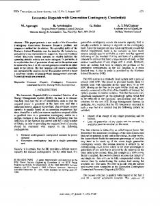
flux, current, or force density along a line or arc can be plotted With a simple command which permits input via the cursor. Energies-can be obtained to facilitate inductance calculations. Numerical output may be printed or stored on disk for later processing by some user specific progFam. To illustrate these features, a transient eddy current analysis of a four-pole, three-phase induction motor is carried out. The blocked rotor condition is assumed (no rotor motion) and the three phase currents create a rotating mmf in the air gap. Figure 1 shows the top half of the machine cross-section which is all that need be modeled by symmetry. Figures 2 and 3 show the phenomena of rotating poles. Other information such as how the current penetrates into the rotor bars can also be obtained graphically.
Condition
=
Air Gap 0.1 mm
,
Pero
B .
,
Periodic boundary
Fig. 1. Outline and boundary conditions for rrnotor.
Fig. 2. Flux Contours at 0.417 msec.
88 SM 643-9
May 1989
Contingency Arming System Implementation for
the Intermountain Power Project HVDC Transmission System
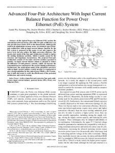
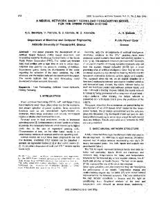
M. J. Beshir, Member, IEEE, J. H. Gee, Member, IEEE, and R. L. Lee, Member, IEEE Los Angeles Department of Water & Power Los Angeles, California, U.S.A. This paper discusses the automated Contingency Arming System (CAS) to trip Intermountain Power Project (IPP) generators based on network transfer level and transmission failure mode. The CAS was implemented to operate irn coordination with other AC/DC controls providing network stability enhancement to the Western U.S. system and increasing the Intermountain DC transfer capability. The IPP two-generator unit output is scheduled on the 787 ±
km 1500 kV bipole HVDC line Southern Transmission System from Delta, Utah, to Adelanto, California. The DC converter equipment has been configured with a nominal bipole capacity of 1600 MW and a unique continuous pole overload capacity of 1200 MW. Other unique AC/DC features adopted in the original transmission planning for stability enhancement included a two per-unit transient pole overload, DC power transfer during faults, fast power recovery and generator transformer neutral resistors. Since these AC/DC controls are not sufficient to meet the stability criteria under certain outage contingencies, it was decided to implement an automated CAS to arm generator units for tripping following certain disturbances. The CAS implemented for IPP consists of two distinct functional activities: arming and triggering. Figure 1 depicts the key elements of the CAS. The arming function is performed by the Energy Control Center computer based on arming charts as illustrated in Figure 2. Monitored real-time system operating parameters are used to deternmine the specific chart set for arming the units to be tripped for a disturbance. Once the CAS is armed, unit tripping is activated by protective relay and converter station signals responding to the system disturbance. The converter sytem has a 1920 MW continuous bipole overload rating based on dynamic overvoltage design limit specified by the converter supplier. To validate the operational capability at the 1920 MW transfer level, study results are provided to demonstrate that stability criteria are met with the coordinated operation of the CAS and the original AC/DC controls. Discussers: W. K. Wong, J. H. Doudna and R. Gunderson.
PATC_R
DISPATCHER ARMING (MANUAL MODE)
TRIP UNIT
Fig. 3. Contours at 1.25 msec.
RELAY PROTECTION
Fig. 1. Pictorial of IPP contingency arming system. IEEE Power Engineering Review, May 1989
41
m
COLU4 CHART SET
~>
SUPERTRIGGER
: :I 5
8
I.
R
g
8
0
1000 500 6500 2000 DC LNE POWER AT INTERMOUNTAW (WV)
2500
Fig. 2. Typical contingency arming chart.
88 SM 692-6 May 1989
An Enhanced LQ Adaptive VAR Unit Controller for Power System Damping J. R. Smith, D. A. Pierre, D. A. Rudberg, 1. Sadighi, and A. P. Johnson Electrical Engineering Department Montana State University Bozeman, MT J. F. Hauer Bonneville Power Administration Portland, OR
Summary Static VAR compensators have been installed in power systems primarily to function in the steady state regulation of voltage levels or reactive power flows. More recently however there has been much interest in utilizing these devices to improve the dynamic performance of power systems. This paper presents an adaptive linear quadratic Gaussian control strategy for static var systems to enhance power system damping and stability. The control strategy uses only local information to dampen oscillatory modes present in the network. The controller calculates an appropriate value of VAr unit susceptance to present to the network at each sampling instant. The calculation of the appropriate susceptance value is based on a reduced-order model of the power system which is obtained on-line by a least squares identification procedure. The controller consists of three main components: an identifier, an adaptive observer, adn an adaptive LQG regulator. The identifier users a recursive least squares type of algorithm to fit a linear, discrete transfer function model to a sequence of input and output signals obtained from the power system. This results in a reduced-order approximation to the actual power system. For this study, VAr unit susceptance is used as the input signal and bus frequency deviation is used as the output signal. The coefficients of the identified transfer function are then sent to both the adaptive observer and the adaptive regulator. The observer is an observable-cannonical representation of the system and it calculates a state vector representing system dynamics. Control of the system is formulated as control of the 42
observer. The adaptive regulator solves the Riccati equation which minimizes a cost function that drives the output of the model to zero with a minimum of control action. The gains calculated from the Riccati iteration are applied to the state vector obtained from the observer and this along with a term from the past control action are combined to give the new control signal or VAr unit susceptance. Simulation results are presented for a nine bus network. The controller is shown to be effective in damping oscillations caused by faults. In one case with no SVC control applied, a disturbance produces instability; but with the controller in place, stability is restored. This case is illustrated in Figs. 1 and 2. The results of this study indicate that the effectiveness of the VAr unit in damping out all oscillations that may occur in a system is dependent upon its location in the network as well as the operating conditions of the power system. The phenomenon illustrated suggests that a very effective way to control oscillatory behavior in a large network is to use carefully located power system stabilizers in conjunction with VAr unit damping. It may also be effective to use an output signal that is derived from a combination of frequency deviation and bus voltage magnitude or other signals that are available locally. Another interesting point illustrated is that under conditions where there is more than one lightly damped or undamped mode present, the size of the reduced-order model used can significantly influence the success of the adaptive control action. In this situation, if one uses a low-order model, the process of damping out one mode may also excite another unmodeled mode. The desired end result may be obtained more quickly and safely if a higher order model is used.
I
Fig. 1. Open-line disturbance with no VAr unit control action.
IEEE Power Engineering Review, May 1989