This paper deals with installation of strain gauges on the external surface of the blast furnace shell in two rows, whereas there will be defined 8 measuring points ...
ISSN 0543-5846 METABK 51(1) 55-58 (2012) UDC – UDK 669.14-418:539.37:620.17=111
P. BIGOŠ, J. KUĽKA, M. MANTIČ, J. ČURILLA
CONTINUAL MEASURING OF LOCAL STRESS VALUES ON SHELL OF THE BLAST FURNACE HEARTH AND OF TOTAL SHELL EXPANSION Received – Prispjelo: 2011-02-06 Accepted – Prihvaćeno: 2011-04-03 Preliminary Note – Prethodno priopćenje
This paper deals with installation of strain gauges on the external surface of the blast furnace shell in two rows, whereas there will be defined 8 measuring points in every row. The final result is evaluation of data obtained during up to 45 days of the operation. In this papers are commentary and discussions to measured time behaviours. The main purpose of this measuring was investigation of impact of salamander on blast furnace shell expansion after its lay off, cooling and next starting of operation. Key words: blast furnace, blast furnace hearth, stress, strain gauges, Neprekidno mjerenje lokalnih naprezanja na plaštu gnijezda visoke peći i ukupnog širenja plašta. Članak daje primjene tenziometrijskog snimanja plašta visoke peći u dva reda, a na svakom redu je postavljeno 8 mjernih mjesta. Završni rezultati su dobijeni na temelju mjerenja tijekom 45 dana. Članak sadrži komentare i rasprave ponašanja u mjernom vremenu. Cilj mjerenja je bilo istraživanje utjecaja salamandera na širenje gnjezda i plašta visoke peći poslije zaustavljanja, hlađenju i sljedećeg pokretanja u rad. Ključne riječi: visoka peć, gnjezdo visoke peći, naprezanje, tenziometrijski snimač
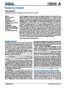
INTRODUCTION This paper describes continual measuring of local stresses on the furnace hearth shell of the open hearth furnace with shell external cooling. Diameter of the furnace hearth is 11 996 mm and the total height from the base is 36 660 mm. There was also performed continuous mechanical measuring of total shell expansion using circumferential and radial gauges. The blast furnace shell is a welded shell construction made from a normalized boiler steel according to the European technical standard Euro S355J2G3 (equivalent to the Slovak technical standard STN 11 483.1) with the yield point value 363 MPa, the Rm (UTS) value is 471 ÷ 608 MPa, the ductility is 22 % and the notch toughness KCU3 = 49 J·cm-2, [1]. The experiment is based on a theoretical assumption of the torque-less theory of rotating shells [2, 3]. The strain gauge methodology was applied, whereas on the selected points of the blast furnace shell were measured increments of relative deformations together with related stresses in meridian and circumferential directions. Application of a ‘half-bridge’ interconnection of the stress gauges, together with thermal compensation, is the most suitable method for such kind of measuring. The thermal compensation is realized by means of a small piece of unloaded steel plate arranged close to the blast furnace shell. The scheme of the blast furnace shell part is in the Figure 1. P. Bigoš, J. Kuľka, M. Mantič, Faculty of Mechanical Engineering TU, Košice, J. Čurilla: U.S.Steel, s.r.o. Košice, Slovakia
METALURGIJA 51 (2012) 1, 55-58
Figure 1 Scheme of the blast furnace part
EXPERIMENT Arrangement of the sensors on 16 measuring points in the area of the blast furnace hearth, together with dimensional data of their positions, are illustrated in the Figure 2. There were chosen the strain gauges 1-XY116/120 and 1-LY11-6/120 produced by the company HBM. The gluing process was performed using the twopart glue X 280, which is specified for the strain gauge applications. Process of its hardening requires normal temperatures. The strain gauges, installed on the blast furnace shell, were insulated against external influences by means of a silicon insulating paste. The compensational strain gauges were insulated using the silicon 55
P. BIGOŠ et al.: CONTINUAL MEASURING OF LOCAL STRESS VALUES ON SHELL OF THE BLAST FURNACE HEARTH... 50
Temperature / °C
40 30
Mechanical damage of sensor T2 due to operation (fall of water cooling protective cover on the temperature sensor)
20 10
T1 T2 T3 T4
18.3.2010
8.3.2010
26.2.2010
16.2.2010
6.2.2010
27.1.2010
0
Figure 3 Values of measured temperature on the blast furnace shell
Figure 2 Disposition of sensors on the extended blast furnace shell
rubber SG 250. Transmission of signals from the sensors into the measuring apparatus was realized by means of shielded input cables. The measuring equipment consists of 4 modular measuring amplifiers with the A/D converter SPIDER 8. The software CATMAN, which is a product of the company HBM, was used for data collection, data processing and for their final evaluation. Temperature of the blast furnace shell was measured by means of the electronic equipment G – RECO TEA, using sensors PT 1000. The time behaviour of temperatures is visible in the Figure 3. From this Figure it is evident that after several measuring days the sensor T2 was damaged mechanically. Its repair was impossible due to current operation of the blast furnace.
EXPERIMENTAL RESULTS Measuring of the stress increments in 16 sensor application points (according to the Figure 2) was performed during 45 days. It started on the 30th of January 2010 at 2:00 p.m. and the measuring was finished on the 15th of March 2010 at 4:30 p.m. There were applied 32 active sensors (for measuring of meridian and circumferential stress increments) and also 32 thermal compensational sensors (for thermal compensation of the meridian and circumferential stress increments). Sev56
eral sensors were damaged successively due to aggressive surroundings during the above-mentioned time period of measuring. It is possible to say, taking into consideration reliability of obtained results, that impact of damaged sensors on the global monitored time behaviour and on the circumferential stress increments on the shell, is less important. There are various reasons of sensor damaging: electric shocks, corrosion, cooling water, mechanical failure of cable or other negative interventions. Time records, i.e. time behaviours of the circumferential stress increments in the measuring points A1 – A8 and B1 – B8 (see Figure 2), measured during 45 days, are illustrated summarily in the Figure 4. Time records of meridian stress increments are not presented in this paper because of their low level and with regard to the purpose of investigation. Mechanical measurement of shell displacement was performed together with strain gauge measuring by means of horizontal bars equipped with rules, as well as it was realized measuring of shell circumferential deformations by means of a wrapped steel belt. Radial increase of the blast furnace shell deformation was monitored in a next way: a set of steel bars was welded perpendicular to the shell and opposite to each of them were welded other bars of the same type (quadratic bar 20 x 20 mm), however they were anchored to another construction, which is independent from the shell. Values of distances between the individual couples of bars were measured in periodical time intervals and in this way was measured radial expansion (in mm) of the blast furnace shell. There were applied 4 couples of bars in four points that were distributed equally around the shell circumference (Figure 2). Measured values of the shell horizontal displacements are illustrated in the Figure 5. It is evident in this figure that measuring of displacements obtained from bars in the point 2 was interrupted after the February 6th 2010, due to an impossible access to this point during current operation of the blast furnace. Reading of distances between bars was performed manually from the installed rules and therefore it was affected by climatic conditions (steam, water, ice). BeMETALURGIJA 51 (2012) 1, 55-58
P. BIGOŠ et al.: CONTINUAL MEASURING OF LOCAL STRESS VALUES ON SHELL OF THE BLAST FURNACE HEARTH...
at point 8 Extension / mm
at point 6
8
at point 4
6
at point 2
4 2
16
160
12
120
8
80 Extension
4
Stress 8.3.2010
26.2.2010
16.2.2010
6.2.2010
0 27.1.2010
18.3.2010
8.3.2010
26.2.2010
27.1.2010
0
16.2.2010
0
40
18.3.2010
Horizontal Bars
6.2.2010
Displacement / mm
10
Stress / MPa
Figure 4 Circumferential stress
Figure 6 Measured values of band extension
Figure 5 Horizontal displacements
cause of this influences there were infiltrated failures into the reading of distance values. Increments of circumferential stresses were calculated from the measured values of displacements in the given times and points (see Figure 5). Time behaviour of circumferential stresses is analogical to the Figure 5 and the maximum stress value (related to maximum displacement value 8 mm) is 140 MPa. If there are compared Figure 4 with the Figure 5, so it can be seen a certain approximate coincidence among the recorded time behaviours. The steel band (strap, tape) was wrapped around the shell of the hearth on the level in the middle between section A and B of the blast furnace (see Figure 2.). This band was fixed between its ends by means of an extension spring and tensioning screw. The rule was fixed independently. There were measured distances between ends of band in periodical time intervals and in this way was monitored development of circumferential deformations. This measuring was affected by cooling water. Therefore the results can be misrepresented in comparison to the average values of circumferential deformation that were obtained by the strain gauges [4]. In the Figure 6 is presented time behaviour of the circumferential deformation of the blast furnace shell, which is measured in the form of the wrapped belt extension (in mm). The related stress values (in MPa) were also calculated using the above-mentioned values, taking into consideration temperature influence from the Figure 3. METALURGIJA 51 (2012) 1, 55-58
Elongation of the band caused by increasing of tensioning force in the spring is negligible in comparison to the circumferential increment of circumference extension of the blast furnace shell.
Discussion and commentary to the blast furnace The most important, i.e. the determining stress increments, are the circumferential increases. Therefore they will be commented in the next part more detailed. If we are taking into consideration the measured circumferential stress values (Figure 4), it is evident that the highest value is 160 MPa approx. The stress time behaviour, calculated from the measuring horizontal bars, reached the maximal stress value in the point of sensor No.6, namely 140 MPa approx. It has to be mentioned that frequency of manual reading of the horizontal displacement wasn’t comparable with frequency of stress increments recording by means of the strain gauges. It is quite possible that manual reading didn’t catch the maximum value. The same idea can be applied also for extensions of the band after correction by thermal dilatation, what is documented in the time behaviour of stress values calculated from the measured extensions, see Figure 6. According to the [4], the critical values of increments (increases) of the circumferential stress, radial displacement and circumferential extension of the blast furnace with diameter 14 000 mm are given in the Table 1. 57
P. BIGOŠ et al.: CONTINUAL MEASURING OF LOCAL STRESS VALUES ON SHELL OF THE BLAST FURNACE HEARTH... Table 1 Proposal of critical (alarm) levels Circumferential stress increase / MPa Extension in circumferential direction / mm Radial displacement / mm
< 165
165 - 220
> 220
< 40
40 - 55
> 55
9
- no action is required (acceptable area) - watch very closely, also watch rate of increase - reduce blast volume and blast pressure
In our case the blast furnace diameter is about 12 000 mm and the measured values are presented in the Table 2. Table 2 Measured levels of stress, extension and displacement on the our blast furnace Circumferential stress increase / MPa Extension in circumferential direction / mm Radial displacement / mm
< 165 26 approx. 8 approx.
- no action is required (acceptable area) - watch very closely, also watch rate of increase
If there are compared data in the Table 2 with the Table 1, it is evident that only the value of radial displacement is situated out of the acceptable area, but this is just a minimal deviation, which is lasting for a short time. However, it is necessary to take into consideration also possible inaccuracy of reading, as well as other unfavourable impacts that can be eliminated by means of an electronic recording system of the real displacement values.
mechanical experiment of shell deformation. This fact enables to simplify process of the shell deformation measuring, i.e. without application of the strain gauge method. The temperature measured on the external blast furnace shell didn’t exceed 50 °C, [5]. The obtained experimental results create an assumption for on-line monitoring of the blast furnace shell deformation.
Acknowledgement: This paper was elaborated in the framework of the Project ITMS code: 26220120060, which is co-financed from the EU and administrated by the Agency of Slovak Ministry of Education for European structural funds, as well as in the framework of the Project VEGA 1/0356/11.
REFERENCES [1] [2] [3] [4] [5]
Bigoš, P. a kol.: Installation of strain gauge detector on blast furnace No.1, Košice, 2009, p. 53., Technical Report, TU Košice Trebuňa, F., Šimčák, F. : Odolnosť prvkov mechanických sústav, EMILENA, Košice, 2008, 980 s., ISBN 80-8073148-9. Trebuňa, F., Šimčák, F. : Príručka experimentálnej mechaniky, Edícia vedeckej a odbornej literatúry, Košice 2007, 1526 p. , ISBN 970-80-8073-816-7. R van Oudenallen, at all. and Danieli Corus BV.: Expansion phenomena in a blast furnace hearth after blow-in, MILLENNIUM Steel 2008, p. 42-48. Dorčák, Ľ., Terpák, J., Podlubný, I., Pivka, L : Methods for monitoring heat flow intensity in the blast furnace wall, METALURGIJA, 49(2010)2, 75-78.
CONCLUSION The acceptable level of conformity was achieved between results of the strain gauge measurement and the
58
Note: English language: Melichar Kopas, Technical University of Košice, Slovakia
METALURGIJA 51 (2012) 1, 55-58