Jan 20, 2000 - is represented by equations for elastic displacements combined with the order parameter equation ... with the continuum theory, it fails to describe it because .... lated to such properties as crack toughness and strain to failure.
Continuum field description of crack propagation I.S. Aranson, V.A. Kalatsky, and V.M. Vinokur
arXiv:cond-mat/0001298v1 [cond-mat.mtrl-sci] 20 Jan 2000
Argonne National Laboratory, 9700 South Cass Avenue, Argonne, IL 60439 (June 23, 2011) We develop continuum field model for crack propagation in brittle amorphous solids. The model is represented by equations for elastic displacements combined with the order parameter equation which accounts for the dynamics of defects. This model captures all important phenomenology of crack propagation: crack initiation, propagation, dynamic fracture instability, sound emission, crack branching and fragmentation. PACS: 62.20.Mk, 46.50.+a, 02.70.Bf
The dynamics of cracks is the long-standing challenge in solid state physics and materials science [1,2]. The phenomenology of the crack propagation is wellestablished by recent experimental studies [3–9]: once a flux of energy to the crack tip passes the critical value, the crack becomes unstable, it begins to branch and emits sound. Although this rich phenomenology is consistent with the continuum theory, it fails to describe it because the way the macroscopic object breaks depends crucially on the details of cohesion on the microscopic scale [10]. Significant progress in understanding of fracture dynamics was made by large-scale (about 107 atoms) molecular dynamics (MD) simulations [11,12]. Although limited to sub-micron samples, these simulations were able to reproduce several key features of the crack propagation, in particular, the initial acceleration of cracks and the onset of dynamic instability. However, detailed understanding of the complex physics of the crack propagation still remains a challenge [13]. The uniform motion of the crack is relatively wellunderstood in the framework of the continuum theory [14]. Most of the studies treat cracks as a front or interface separating broken/unbroken materials and propagating under the forces arising from elastic stresses in the bulk of material and additional cohesive stresses near the crack tip [15–18]. Although these investigations revealed some features of the oscillatory crack tip instability, they are based on built-in assumptions, e.g., on specific dependence of the fracture toughness on velocity, structure of the cohesive stress etc. To date there is no continuum model capable to describe in the same unified framework the whole phenomenology of the fractures, ranging from crack initiation to oscillations and branching. In this Letter we present a continuum field theory of the crack propagation. Our model is the wave equations for the elastic deformations combined with the equation for the order parameter, which is related to the concentration of material defects. The model captures all important phenomenology: crack initiation by small perturbation, quasi-stationary propagation, instability of fast cracks, sound emission, branching and fragmentation. Model. Our model is a set of the elasto-dynamic equa-
tions coupled to the equation for order parameter ρ. We define the order parameter as the relative concentration of point defects in amorphous material (e.g., microvoids). Outside the crack (no defects) ρ = 1 and ρ = 0 inside the crack (all the atomic bonds are broken). At the crack surface ρ changes from 0 to 1 on the scale much larger than the inter-atomic distance, justifying the continuum description of the crack [19]. We consider the two-dimensional geometry focusing on the so-called type-I crack mode, see Fig. 1. Equations of motion for an elastic media [20] are: ρ0 u ¨i = η∆u˙ i +
∂σij , j = 1, 2. ∂xj
(1)
ui are the components of displacements, η∆u˙ i accounts for viscous damping, η is the viscosity coefficient [21], ρ0 is the density of material. In the following we set ρ0 = 1. The stress tensor σij is related to deformations via � � σ E uij + ˙ ij (2) ull δij + ν ρδ σij = 1+σ 1−σ where uij is the elastic strain tensor, E is the Young’s modulus and σ is the Poisson’s ratio. To take into account effect of plastic deformations inside the material we introduce dependence of E upon ρ. For simplicity we consider linear dependence E = E0 ρ, where E0 is the regular Young’s modulus. The term ∼ ν ρ˙ in Eq. (2) accounts for the hydrostatic pressure created due to generation of new defects, ν is the constant which can be obtained from comparison with the experimental data. Although this term can be formally interpreted as the hydrostatic pressure due to thermal expansion, we stress that the thermal expansion may be not the only mechanism contributing to the magnitude of this term. There is experimental evidence that the temperature at the crack tip can be of the order of several hundred degrees [22]. However, this would imply the concept of thermal equilibrium which is unlikely to be achieved at the crack tip. One can observe that Eqs. (1) are linear elasticity equations for ρ = 1, i.e., outside the crack, and have trivial dynamics for ρ = 0 (there is no dynamics inside crack).
1
RL where C is a constant of integration (C 0 dy/ρ(y) = √ Lδ), β = b/(1 + µC), and ξ = y 1 + µC. The solution to Eq.(4) satisfying the BC for L → ∞ is: p √ (β + 1)(1 − β/2) cosh(ξ β − 1) + 2 − β p , (6) ρ= √ (β + 1)(1 − β/2) cosh(ξ β − 1) + 2β − 1
We assume that the order parameter ρ is governed by pure dissipative dynamics which can be derived from the ”free-energy” type functional F , i.e., ρ˙ = −δF /δρ. Following Landau ideas on phase transitions [23], we adapt the simplest form for the ”free energy” F ∼ R dxdy(D|∇ρ|2 + φ(ρ)), where the ”local potential energy” φ has minima at ρ = 0 and ρ = 1. Choosing the polynomial form for φ(ρ) we arrive at ρ˙ = D∆ρ − aρ(1 − ρ)F (ρ, ull ) + f (ρ)
∂ρ u˙ l . ∂xl
This solution exists for 1 < β < 2. A deep and wide crack opening is attainable if 2−β = ǫ ≪ 1. In pthis case the BC for uy can be reduced to δL = C(L + π 3/(ǫb)) yielding an equation for ǫ since C = (b/2 − 1)/µ. For ǫ ≪ 1 the width pof the crack opening d, defined as ρ(d/2) = 1/2, is d = 2/b ln(24/ǫ). After exclusion of ǫ one arrives at r √ � �! 2µδ 8 8b (7) ln L −1 d= b π b−2
(3)
The solution to Eq. (7) exists only if δ exceeds some critical value δc given by δc ≈ (b/2 − 1)/µ, which leads to the relation between strain to failure δc and the material parameters µ and b. The logarithmic, instead of linear, dependence of crack opening on system size L in Eq. (7) is a shortcoming of the model resulting from oversimplified dependence of the function F on ull . To study the dynamics of cracks we perform numerical simulations with Eqs. (1)-(3). We use explicit secondorder numerical scheme with the number of grid points up to 4000 × 800. Our model reproduces all important phenomenology: crack arrest below the critical stress, crack propagation above the critical stress, oscillations of the crack velocity, crack branching and fragmentation. Selected results are presented in Figs. 2-5. Quasi-stationary propagation. We considered crack propagation initiated from a long notch with the length of the order 100 units. At relatively small loadings δ we have observed a quasi-stationary propagation (no oscillations). The crack produces the stress concentration near the tip, and the stress is relaxed behind the tip, see Fig. 2b. The distribution of shear (Figs. 2c,3) is close to that expected from the elasticity theory. The angular dependence Σxy (θ) of the shear stress σxy near the tip is close to the theoretical dependence σxy (r, θ) ∼ r−1/2 Σ0xy + ..., where Σ0xy (θ) = sin(θ) cos(3θ/2) obtained for the infinite stationary crack. The discrepancy can be attributed to finite-size effects, velocity correction, etc. We computed the angle θm of the maximum shear stress vs crack speed V normalized by the Rayleigh speed VR . (see Fig. 2c, 3). As one derives from the linear elasticity, the angle increases with the speed of the crack [14], in an agreement with our numerical results.
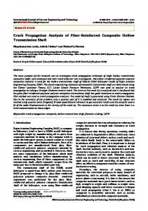
y L
Lδ+L
Coupling to the displacement field enters through the position of the unstable fixed point defined by the function F (ρ, ull ), where ull is the trace of the strain tensor. Constraint imposed on F (ρ, ull ) is such that it must have one zero in interval 1 > ρ > 0: F (ρc , ull ) = 0, 1 > ρc > 0, and ∂ρ F (ρ = ρc , ull ) < 0. The simplest form of F satisfying this constraint is F (ρ, ull ) = 1 − (b − µull )ρ, although any monotonic function of ρ will show the qualitatively similar behavior. Here β and µ are material constants related to such properties as crack toughness and strain to failure. Coefficients D and a can be set to 1 by rescaling t → at, xi → νxi where ν 2 = D/a. The last term in Eq. (3) represents the coupling of the order parameter to the velocity field u˙ and is responsible for the localized shrinkage of the crack due to material motion. Since the specific form of the function f (ρ) is irrelevant, we take f (ρ) = cρ(1 − ρ) to insure that f vanishes at ρ = 0 (no material) and ρ = 1 (no defects), where c is the dimensionless material constant. From our simulations we have found that this term in Eq. (3) is crucial to maintain the sharp form of the crack tip.
L
Lδ+L
x
FIG. 1. Schematic representation of fixed-grips loading
Static solutions. Eqs. (1)-(3) have a dip-like solution corresponding to the open gap far behind the crack tip (a “groove” along x-axis for our geometry, see Fig.(1)). The static one-dimensional equations read: ∂ρuyy ∂2ρ − ρ(1 − ρ)(1 − (b − µuyy )ρ) = 0, (4) = 0, ∂y ∂y 2 with the fixed-grips boundary conditions (BC): uy (y = ±L) = ±Lδ (δ — relative displacement), ρ(y = ±L) = 1, and ∂y ρ(y = 0) = 0. Exclusion of uyy from Eqs. (4) yields uyy = C/ρ, ∂ξ2 ρ = ρ(1 − ρ)(1 − βρ),
(5)
2
The calculated dependence of the crack tip velocity on the effective fracture energy G ∼ δ 2 , shown on Fig. (4), demonstrates an excellent agreement with the experimental data from Ref. [5]. The instability of the crack occurs when the velocity becomes of the order of 55% of the Rayleigh speed for the parameters of Fig. 2a-e. For parameters of Fig. 2f we have found lower value of the critical velocity, namely about 32% of the Rayleigh speed. In all cases the instability manifests itself as pronounced velocity oscillations, crack branching and the sound emission from the crack tip. Our calculations indicate absence of the minimal crack velocity, the so-called velocity gap [10]. The initial velocity jump, seen experimentally as well as in some of our simulations (see Fig. 4), is attributed to the fact that the initial crack (notch) is too short or too blunt. 0.8
V/VR
0.6
0.2
FIG. 2. Color-coded images of ρ(x, y) (a); hydrostatic pressure p = −ρ(uxx + uyy ) (b); and shear ρ(uxy + uyx ) (c). Domain size 800 × 200, number of grid points 1600 × 400, and δ = 0.05, η = 0.25, E0 = 10, σ = 0.2, b = 2.25, c = 11, ν = 2.3, µ = 9.2; ρ(x, y) for unstable propagation at δ = 0.089 (d) and δ = 0.11 (e). Domain size 1200 × 200, 2400 × 400 grid points. (f) ρ(x, y) for propagation with fragmentation, E0 = 100, σ = 0.36, c = 16, ν = 2.3, µ = 54 and δ = 0.03, Domain size 2000 × 400, 4000 × 800 grid points.
0.0 0.0
Instability of cracks propagation. Taking the sufficiently large values of ν and c and starting from short cracks with the large load we observed consecutive crack branching. Since Eqs. (1)-(3) are homogeneous, these secondary crack branches typically retract after the stress at the tip of the shorter crack relaxes. Although this retracting may indeed take place, e.g., in vacuum the small cracks may heal, the oxidation of the crack surface and lattice trapping would prevent cracks from healing. In order to model these effects, one can introduce an additional field representing concentration of oxygen and then couple it to the order parameter. In some simulations, we multiplied r.h.s. of Eq. (3) by a monotonic function w(x − xtip ): w(x > 0) = 1 and w(x → −∞) → 0, where xtip is the crack tip position. Thus, we slowed down the evolution of ρ behind the crack tip, which, in turn, prevents secondary cracks from healing. We succeeded to
0.0
Σxy
θm
0.2
-0.2 -0.4 -0.6 -0.8
0
0.2
0.3
0
θ m50 0.4
100
θ 0.5
4.0
FIG. 4. Crack velocity V /VR vs G/Gc , where Gc s the onset value for crack propagation. ◦ correspond to stable propagation, × to unstable propagation, parameters the same as for Fig. 2a-e, ⋄ show the experimental results from Ref. [5] normalized by VR = 1300 m/s, the Rayleigh speed in PMMA in the frequency range of 0.6-1 MHz [7].
30
10
2.0
G/Gc
40
20
0.4
150
0.6
V/VR FIG. 3. θm vs crack velocity V for parameters of Fig. 2a-c. Solid line shows θm vs V from linear elasticity [14], ◦ show result of numerical simulations. Inset: angular dependence of shear stress Σxy (filled circles). The dependence from linear elasticity theory for infinite crack is shown in solid line.
3
obtain realistic crack forms, see Fig. 2d,e. For fast cracks the “freezing” is not a necessity, since the retraction is rather slow. Fig. 2f shows results without freezing: massive crack branching along with crack healing are present. Far away from the crack tip we have registered oscillations of hydrostatic pressure (see Fig. 5, Inset), which is a clear indication of the sound emission by the crack tip. The sound waves reflected from boundaries may also induce velocity oscillations, but they do not provide a mechanism for branching [24]. Increase in the applied displacement δ results in increase of amplitude and the number of secondary branches (cm. Figs. 2d-f and 5).
[1] M. Marder and J. Fineberg, Physics Today 49, 24 (1996) [2] B. Lawn, Fracture in Brittle Solids (Cambridge University Press, Cambridge, 1993), 2nd ed. [3] J. A. Hauch, D. Holland, M. P. Marder, and H. L. Swinney, Phys. Rev. Lett. 82, 3823 (1999) [4] E. Sharon and J. Fineberg, Nature 397, 333 (1999) [5] E. Sharon, S. P. Gross, and J. Fineberg, Phys. Rev. Lett. 74, 5096 (1995); ibid 76, 2117 (1996). [6] J.F. Boudet, S. Ciliberto, and V. Steinberg, Europhys. Lett. 30, 337 (1995) [7] J.F. Boudet, S. Ciliberto, and V. Steinberg, J. Phys. II (France) 6, 1493 (1996) [8] J. Fineberg, S. Gross, M. P. Marder, and H. L. Swinney Phys. Rev. Lett. 67, 457 (1991) [9] D. Daguier, S. Henaux, E. Bouchaud, and F. Creuzet Phys. Rev. E 53, 5637 (1996) [10] J. Fineberg and M. Marder, Phys. Reports 313, 1 (1999) [11] F. Abraham, Phys. Rev. Lett. 77, 869 (1997); S. J. Zhou, D. M. Beazley, P. S. Lomdahl, and B. L. Holian, Phys. Rev. Lett. 78,479 (1997); R. K. Kalia, A. Nakano, K. Tsuruta, and P. Vashishta, Phys. Rev. Lett. 78 689 (1997); D. Holland and M. Marder Phys. Rev. Lett. 80, 746 (1998); F. Cleri, S. Yip, D. Wolf, S. R. Phillpot, Phys. Rev. Lett. 79, 1309 (1997) [12] Computing in Science & Engineering, 1 (1999) dedicated to dynamic fracture analysis. [13] Cracks: More Than Just a Clean Break, Special Section in Science 281, 943 (1998). [14] L.B. Freund, Dynamic Fracture Mechanics (Cambridge University Press, N.Y., 1990). [15] E.A. Brener and V.I. Marchenko, Phys. Rev. Lett. 81, 5141 (1998) [16] M. Adda-Bedia and M. Ben Amar, Phys. Rev. Lett. 76, 1497 (1996); M. Adda-Bedia, R. Arias, M. Ben Amar, and F. Lund, Phys. Rev. Lett. 82, 2314 (1999) [17] E. S. C. Ching, J. S. Langer, and H. Nakanishi, Phys. Rev. E 53, 2864 (1996). [18] S. Ramanathan and D. S. Fisher, Phys. Rev. Lett. 79 877 (1997) [19] The characteristic scale of ρ is related to the damage zone width on the crack surface and is of the order of a micron for brittle polymers (the craze layer width, R.P. Kambour, J. Polymer Sci. A-2, 4, 17 (1966)). [20] L.D. Landau and E.M. Lifshitz, Theory of Elasticity, (Pergamon Press, Oxford, 1964). [21] The specific form of the dissipative terms does not change qualitatively the mechanism of crack tip instability. [22] K. N. G. Fuller, P.G. Fox and J.E. Field, Proc. R. Soc. Lond. A 341, 537 (1975); J. A. Kallivayalil and A. T. Zender, Int. Jour. of Fracture 66, 99 (1994) [23] L.D. Landau and E.M. Lifshitz, Statistical Physics, (Pergamon Press, Oxford, 1980). [24] The interaction with sound can be reduced by introducing additional damping term ∼ u˙ to the rhs of Eq. (1). [25] M. Marder, Phys. Rev. E 54 3442 (1996) [26] D.A. Kessler and H. Levine, Phys. Rev. E 59, 5154 (1999)
1.0
0.5
0.131
p
V/VR
0.8
0.129
0.2 0.127 200
0.0
400
600
800
t 0
200
400
600
800
t FIG. 5. The crack tip velocity V normalized by Rayleigh velocity VR vs time for δ = 0.089 (solid line) and δ = 0.11 (dashed line), parameters of Fig. 2d,e. Inset: oscillations of pressure p far away from the crack tip for δ = 0.089.
Some estimates are in order. Our unit of length λ is the width of the craze zone and is of the order of a micron in PMMA [19]. The unit of time τ is obtained from λ ∼√ 1µ and Rayleigh speed VR ∼ 103 m/s, which gives τ ∼ E0 10−9 s. In experiments [4–8] the characteristic time of velocity oscillations τ0 is of the order of 1 µs. Our model gives τ0 ∼ 102 τ ∼ 0.1 – 1 µs for E0 = 10 – 100. Conclusion. We have developed a continuum field theory of the crack propagation. The central element of our approach is the description of crack by the order parameter. The proposed approach enables us to avoid the stress singularity at the crack tip and to derive the tip instability. Our model is complimentary to MD simulations of cracks and allows for a description of fracture phenomena on large scales. The parameters of our model can be obtained from comparison with the experiment. It will be interesting to derive the order parameter equation from discrete models of crack propagation [25,26]. We are grateful to M. Marder, H. Swinney, J. Fineberg, V. Steinberg, H. Levine, E. Bouchaud, A. Bishop, I. Daruka for stimulating discussions. This research is supported by US DOE, grant W-31-109-ENG-38.
4