Control Strategies for Power Smoothing Using a ... - IEEE Xplore
Recommend Documents
the SRM to operate as a motor/generator, storing or retrieving energy from a rotating flywheel. In order to increase the rota- tional energy stored in the flywheel, ...
AbstractâIn this paper, a power smoothing system, based on a switched reluctance machine (SRM) driving a flywheel, is pre- sented. The SRM is controlled to ...
Review of Control Strategies for Power Quality. Conditioners. Norman Mariun, Ahsanul Alam, Senan Mahmod and Hashim Hizam. ;? t: I. Abstruct-Active power ...
important one. In order to improve the competitiveness of the wind power plants, there are ongoing researches to decrease cost per energy unit and increase the ...
Muhammad Fayaz Khan, Raza ul Islam and Jamshed Iqbal*. Robotics and Control Research (RCR) Group,. Department of Electrical Engineering,. COMSATS ...
any speed and power. Simulation results using the. MATLAB software package for a'specific six-pulse con- trolled rectifier fed pmdc motor are presented for two.
AbstractâThis paper presents a novel control strategy for power smoothing in wind energy applications, especially those feeding a stand-alone load.
I Energy Engineering Department, School of Engineering, University of Seville, Seville, ... operate when the stored energy or the renewable energy supply is.
Power Electronics and Control for. Wind Power Systems. Florin Iov, Senior Member IEEE, Frede Blaabjerg, Fellow IEEE. Department of Energy Technology.
Regional Wind Power Forecasting Based on Smoothing Techniques, With Application to the Spanish Peninsular System. Miguel G. Lobo and Ismael Sánchez.
AbstractâEfficient regional forecasting is a critical task for system operators and utilities that manage the generation of various wind farms spread over a region.
H-bridge (CHB) multilevel inverters are flexibly deployed in order to enhance the power quality and redundancy. The HPS employs fuel cell (FC) as the main ...
with zero injected reactive power (unity power factor at grid). Two versions of the proposed controller are introduced, namely, open-loop and closed loop ...
Without Load and Filter Current Measurement. Engin Ozdemir. Mehmet Ucar. Metin Kesler. Murat Kale. Kocaeli University. Kocaeli University. Kocaeli University.
system model, which includes a turbine governor, exciter, synchronous ..... to the frequency deviation, acting as a very large-scale energy- storage battery with ...
AbstractâThe random and intermittent nature of wind power. (WP) makes the integration of large-scale wind farms into power system problematic. The energy ...
vanadium redox flow battery (VRB) based energy storage system (ESS) with many advantages are added at the exit of wind farm. A dynamic mathematic model ...
AbstractâA low cost universal input voltage single-controller power factor correction converter for a 200 W power supply is pro- posed. It consists of the PFC part ...
vanadium redox flow battery (VRB) based energy storage system (ESS) with many advantages are added at the exit of wind farm. A dynamic mathematic model ...
Lifetime Cost Optimized Wind Power Control. Using Hybrid Energy Storage System. Dongsheng Liâ , Fenglong Lu§, Qin Lv§, Li Shang§. â Tongji University ...
Dec 27, 2011 - control system that consumes absolute zero power in standby mode. ... Index Terms âHome Appliances, Zero Standby Power, Light.
from the perspective of non-cooperative game theory, and an algorithm for joint rate and power control is presented. A new utility function for mobile terminals is ...
Control Strategies for Power Smoothing Using a ... - IEEE Xplore
AbstractâThis paper presents a novel control strategy for power smoothing. The system is based on a sensorless vector-controlled induction machine driving a ...
IEEE TRANSACTIONS ON INDUSTRIAL ELECTRONICS, VOL. 51, NO. 3, JUNE 2004
603
Control Strategies for Power Smoothing Using a Flywheel Driven by a Sensorless Vector-Controlled Induction Machine Operating in a Wide Speed Range Roberto Cárdenas, Member, IEEE, Rubén Peña, Member, IEEE, Greg M. Asher, Member, IEEE, Jon Clare, Member, IEEE, and Ramón Blasco-Giménez
Abstract—This paper presents a novel control strategy for power smoothing. The system is based on a sensorless vector-controlled induction machine driving a flywheel. The problem of regulating the dc-link voltage against input power surges or sudden changes in load demand is addressed. The induction machine is controlled to operate in a wide speed range by using flux weakening above rated speed. A model reference adaptive system observer is used to obtain the rotational speed in the whole speed range. The observer parameters are adapted during flux weakening in order to obtain close tracking of the flywheel speed. Experimental results for the operation of the induction machine between zero to more than twice base speed are presented and discussed. Index Terms—Induction machines, power conditioning, power generation, wind energy.
I. INTRODUCTION
F
LYWHEELS are used as energy buffers in order to store or retrieve energy into a stand-alone load [1]–[4] or small generation system. They are also used for power smoothing in wind energy conversion system (WECS), where changes in the wind velocity can produce unacceptable variations on the power or voltages supplied into a stand-alone load or weak grid [1]–[4]. Others applications of flywheels are in weak utilities where the electrical energy is obtained from wind-diesel systems. In these applications, the lack of a temporary energy buffer produces not only fluctuations in the generator output voltage but also an unacceptable number of start/stop cycles of the diesel engine if a temporary buffer is not available [3], [4]. Both induction and permanent-magnet (PM) machines are appropriate for flywheel storage and power smoothing applications. A PM implementation was reported in [4]. The PM machine has the advantage in efficiency and a net flywheel PM generator system efficiency of 93.7% is reported in [5]. However, the PM machine is less rugged, less robust to temperature and significantly more expensive than the induction machine Manuscript received February 12, 2002; revised June 6, 2003. Abstract published on the Internet January 14, 2004. This work was supported by Fondecyt Chile under Contract 1000979 and by the British Council. R. Cárdenas and R. Peña are with the Electrical Engineering Department, University of Magallanes, Punta Arenas, Chile (e-mail: [email protected]). G. M. Asher and J. Clare are with the Electrical and Electronics Engineering Department, University of Nottingham, Nottingham NG7 2RD, U.K. (e-mail: [email protected]). R. Blasco-Giménez is with the Department of Systems Engineering and Automation, Polytechnic University of Valencia, Valencia, Spain (e-mail: [email protected]). Digital Object Identifier 10.1109/TIE.2004.825345
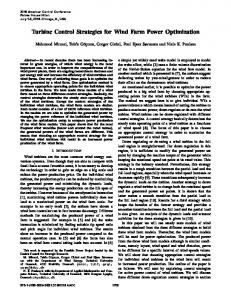
Fig. 1. Compensation system proposed in [1].
(IM) [6]. The IM is, therefore, a good candidate for flywheel drives, especially at higher powers, being robust and cheap. A 50-kW cage IM drive for power smoothing was reported in [3] and [7] while a 70-MVA doubly fed induction flywheel drive is proposed in [8]. Reported efficiencies for IM drives are slightly less than that for PM drives [10] and an efficiency of approximately 90%, reported in [11] for a 500-kW cage IM wind turbine drive, is typical. In recent years, high-efficiency induction motors with efficiencies approaching 95% at 100 kW have become available (see EU regulation IEC34-2 -[9]) and compare well with PM machines of similar rating. The machine efficiencies also compare well with the 80% efficiency obtained with chemical batteries [5]. In previous work related to power smoothing, a flywheel driven by an IM has been used as an energy buffer in a winddiesel system [3]. However, scalar control with slow dynamic performance was used to control the speed of the machine– flywheel set. With such control the machine torque is not controlled directly and this results in suboptimal voltage regulation. In [7] a sensored vector-controlled induction machine driving a flywheel is used for power smoothing in a WECS using variable-speed wind turbines; however, no formal analysis of the system dynamic is presented, the controller design is not discussed, and feedforward compensation is not used. In a previous paper by the authors [1], the power smoothing control strategy for the system shown in Fig. 1 was discussed. When the dc-link voltage decreases, the IM is controlled to operate as a generator, transforming the inertial energy stored in
IEEE TRANSACTIONS ON INDUSTRIAL ELECTRONICS, VOL. 51, NO. 3, JUNE 2004
Proposed control system.
the flywheel into electrical energy supplied to the capacitors. When the dc-link voltage increases, the IM is controlled to operate as a motor, transferring energy from the capacitors to the flywheel. The control system proposed in [1] considered neither flux-weakening operation nor sensorless operation. Flux-weakening operation is appropriate for power smoothing, because, for a given inertia, the energy stored in the flywheel is dependent on the square of the rotational speed [5]. Sensorless operation is also desirable. The use of a position encoder has several drawbacks in terms of robustness, cost, cabling, and maintenance. In the small power range, the cost of a position encoder is almost the same than that of an IM. For these reasons sensorless control and flux-weakening operation of an IM, for power smoothing, are addressed in this paper. Fig. 2 shows the control structure proposed in this paper, including the dc-link voltage regulation. The control system is based on a direct rotor-flux-oriented (DRFO) vector control of current and voltage values the IM driving the flywheel. The are referred to the reference frame aligned to the rotor flux and take dc values in steady state. A novel method to obtain the flux demand as a function of both the electrical frequency and the dc-link voltage is proposed in this paper. This function is calculated offline and stored in a lookup table. The rotor flux is calculated from the machine voltages and currents (“Voltage Model” in Fig. 2) and is used as the feedback signal for the flux controller and also to calculate the electrical angle for the vector rotators. A model reference adaptive system (MRAS) [12], [13] which is used to update a nonestimates the rotational speed linear gain (see Fig. 2) tuning the dc-link voltage controller. The estimate is also input to a feedforward compensation term which improves the performance of the dc-link voltage control loop as reported in [1]. When the machine is operated at reduced flux, the magnetizing inductance varies [14], [20]–[22]. To maintain
the accuracy of the MRAS system, despite the variations in the magnetizing inductance, a lookup table is used to update the parameters of the MRAS observer. In the following sections, the control system shown in Fig. 2 is discussed in detail. Experimental results obtained from an experimental prototype of 3.5 kW will be presented and fully analyzed. II. FLUX WEAKENING Flux-weakening control of the IM is usually accomplished by regulating the rotor flux according to the following control law [20]–[22]:
(1) where is the nominal flux and , the rotational and base speeds, respectively. This control method is widely used in the literature but it does not produce optimal performance in terms of power generation at the output [15]–[17]. According to [15] the control strategy of (1) can produce up to 35% less power when compared with an optimal flux-weakening strategy. The flux-weakening control method used in this work is based mainly in the strategy reported in [17]. A. Flux Weakening for Maximum Generation of Power In steady state, the equations of a rotor-flux-oriented machine are [18], [19] (2) (3)
CÁRDENAS et al.: POWER SMOOTHING USING A FLYWHEEL DRIVEN BY A SENSORLESS VECTOR-CONTROLLED INDUCTION MACHINE
605
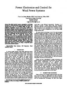
Symbols have their normal meaning and are listed in Appendix A. Neglecting the stator resistance, the currents , can be calculated as (4) (5) If the current and voltage limits are considered, the following equations are obtained: (6) (7) The power obtained from the machine is (8) where the coefficient arises from the 2–3 axes scaling. Replacing (4) and (5) in (8) yields (9) Equations (6)–(9) can be used to describe the operation of the IM during flux weakening. The voltage limit is given by (6), representing a circle in the ( , ) plane. Operation at maximum current is given by (7) representing an ellipse in the ( , ) plane. Finally, the generated power is obtained from (9) which is an asymptotic curve in the ( , ) plane. in (9) is negative for generation and positive for motoring. For a given frequency , Fig. 3(a) shows the current-limit ellipse and the voltage-limit circle. Three asymptotic curves rep) resenting different values of constant power generation ( . Flux-weakening operare also shown where ation has two zones [15]–[17]. In the first zone the maximum power is obtained when the IM is operated at maximum voltage and current [see Fig. 3(a)]. The second zone for flux-weakening operation is produced at high frequencies where, because of the leakage inductance, a substantial value of voltage is necessary to obtain the full value of [see (2)]. In the second zone, the maximum power output is produced when the machine is not operated at maximum current. Because of the mechanical stresses produced by a flywheel rotating at high speed, in this work the operation of the IM has been limited to approximately twice base speed. In this range the system is operating in the first zone where the maximum power is obtained at the intersection between the current-limit ellipse and voltage-limit circle. However, because the control system proposed in this paper is based upon lookup tables, it is simple to extend the operation at the flux-weakening second zone. B. Lookup Table Implementation A robust method to maximize the power output in the first flux-weakening zone is proposed in [17]. In this method the machine is operated at maximum voltage following the trajectory A is reached, shown in Fig. 3(b). When the maximum current the machine is operating at the maximum output for a frequency . The main advantage of this approach is robustness because the control is not dependant on the machine parameters. However it produces a reduced dynamic response because there is
Fig. 3. Flux-weakening operation of the IM. (a) Operation at maximum power. (b) Control trajectory to obtain a high dynamic response.
little voltage margin left to increase the torque current , unless the flux current is reduced. To improve the torque dynamics, trajectory B shown in Fig. 3(b) is used in this work. the intersection point between the curFor each frequency rent-limit ellipse and voltage-limit circle is calculated. From this intersection point a flux reference is obtained. This reference ) even when the machine is operis fixed (for a given , ating with a low current, i.e., there is always in the system the necessary amount of voltage margin for when a fast change in the electrical torque is required. This control strategy is further discussed in [15] where the voltage margin necessary, for fast dynamic response in the electrical torque, is analyzed. The use of trajectory B, to improve the dynamic response of the electrical torque is also discussed in [17]. It is outside the scope of this paper to fully analyze flux-weakening operation of IMs and the interested reader can find more information in [14]–[17] and [20]–[22]. For this application, the flux reference is stored in the lookup table and is computed by solving (2)–(7) considering saturation (see Fig. 5) and the effect of stator resistance. In the experimental rig, the magnetizing inductance has been calculated
606
IEEE TRANSACTIONS ON INDUSTRIAL ELECTRONICS, VOL. 51, NO. 3, JUNE 2004
by supplying an unloaded IM with variable flux, using a V/F control strategy. The magnetizing inductance is then calculated from the reactive power using the method reported in [18]. and Besides the flux demand, the magnetizing inductance , are also the maximum current , obtained as stored in a lookup table. C. Flux Demand as a Function of DC-Link Voltage Variations In most of the applications an inverter will be connected to the dc-link capacitors in order to provide electrical energy to is a function of the an ac load. Therefore, the reference voltage used by the ac load and the nominal voltage of the IM. Additionally, the reference voltage can also be modified in order to improve voltage regulation at the load. In the general case it is assumed that the dc-link voltage can be varied depending on the IM and load voltage requirements. As discussed previously, during flux weakening, the maximum power generation is produced when the current-limit ellipse intersects with the voltage-limit circle. Solving (6) and (7) the quadrature voltage at the intersection is calculated as (10) The steady-state rotor flux is obtained from (5) as (11) Replacing (11) in (10), the following expression is obtained: (12) The voltage limit is a function of the dc-link voltage and the pulsewidth-modulation (PWM) technique being used (13) Replacing (13) in (12) and rearranging,
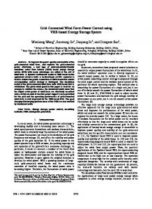
Fig. 4. Flux variation with respect to the dc-link voltage. (a) Non-normalized curves. (b) Normalized curves.
(14) , From (14) it is concluded that the flux is a function of i.e, if the dc-link voltage reference is changed, the flux should also be changed in order to obtain maximum power at the output of the IM. Using a calculation that considers saturation and the effects of the stator resistance, the flux trajectories shown in Fig. 4(a) have been obtained for dc-link voltages of approximately 500, 590, and 680 V. Because the value of is changed a flux curve is obtained for each dc-link voltage. Fig. 4(b) shows the normalized flux trajectories. These are obtained by correcting the per-unit frequency by the factor 1/0.85 and 1/1.15 for the first and third curves, respectively. It can be seen in Fig. 4(b) that the curves do not match perfectly since in (10)–(14) stator resistance is not considered (For the normalized curves are equals despite the dc-link voltage variation). However, for small variations around an operation point, the difference between the normalized curves is negligible. In this work variations of less than 12% around a dc-link voltage of 590 V are used. From the results shown in Fig. 4, the searching index for the flux demand lookup table is , where is the demanded dc-link voltage.
III. MRAS OBSERVER The rotational speed is necessary for the implementation of the control algorithm discussed in Section IV. In order to obtain an estimation of the rotational speed an MRAS observer is used in this implementation [12], [13]. The MRAS observer is based on two models. The voltage model is used to obtain the reference flux and it is obtained as (15) The rotor flux can also be obtained from the current model. The flux from the current model is (16) The reference flux derives from (15), and the estimated flux from (16). By adjusting the rotational speed it is possible to reduce the error between the reference and estimated flux. The error is usually defined as (17) Equations (15)–(17) are used to implement the speed observer. The MRAS is relatively simple to implement for IM operating
CÁRDENAS et al.: POWER SMOOTHING USING A FLYWHEEL DRIVEN BY A SENSORLESS VECTOR-CONTROLLED INDUCTION MACHINE
607
IV. CONTROL SYSTEM DESIGN For the design of the dc-link voltage control system a transfer function is required relating the dc-link voltage with . The transfer function may be obtained using the power balance between the dc-link side and the IM side [1]. The power balance is obtained as (18) represents the inverter and iron power losses, is where and are defined in Fig. 1. the dc-link capacitance, and The coefficient arises from the 2–3 axes scaling. Using the machine parameters and assuming rotor flux orientation [19], , , , and are given by
(19) Fig. 5.
Magnetizing inductance as a function of the current i .
at full flux, i.e., below base speed. However, there are few publications on the use of the observer for field-weakening operation [21]. The main difficulty of the MRAS observer during flux weakening is the variation of the machine parameters [20]–[22] is a function of the magsince the magnetizing inductance versus for the netizing current . Fig. 5 shows the curve machine used in the experimental prototype. The variation of is also reflected in and the overall leakage coefficient . In this paper, a lookup-table-based method is proposed to maintain the MRAS observer tuned. The lookup table is used to as a function of the demand flux . Fig. 6 store the value of shows the implementation of the MRAS observer. The voltage model is used to obtain the rotor flux where a bandpass filter is used as a modified integrator to block the dc components of the measured voltage and currents. From the voltage model, the flux magnitude is obtained and also the electrical angle . The electrical frequency is obtained by differentiating and using a low-pass filter (not shown in Fig. 6). Because of the high inertia the variation in the electrical frequency is slow and the time delay introduced by this filter is negligible. and the dc-link reference voltage , an index for From searching the lookup tables is obtained. From the lookup tables, , the flux set point , the maximum quadrature current and the magnetizing inductance are obtained. The set point and the flux magnitude are necessary in the flux control system shown in Fig. 2. In the first flux-weakening zone, when the current is reduced the maximum current is increased is calculated from a lookup table and [17]. Therefore, used in a variable limiter (see Fig. 2). Finally, there is another lookup table to obtain the value of . The estimation of the magnetizing inductance is used to calculate the values of , , , and . These parameters are used in the MRAS observer and in the DRFO control. At the bottom of Fig. 6 is the current model. The error calculated from (17) is driven to zero by using a proportional–integral (PI) controller. The output of this PI controller is the estinecessary in the dc-link voltage conmated rotational speed trol system. This control system is discussed in the next section.
Using (19) it can be shown that the power balance can be derived as
(20) where is the flywheel speed (in electrical radians per second). We can linearize (20) about the reference , assuming that and are almost constant (because of the large flywheel inertia they have a slow variation). The linearized transfer function be) is then obtween the dc-link voltage and (neglecting tained from (20) as
(21)
A. Feedforward Compensation The principle of feedforward compensation is based on the parametric model of the machine and converter and relates the to . Since the flywheel inertia will fluctuation current be large (the speed dynamics will be slow), and neglecting the , , then the steady-state variation in the energy stored in system equations may be used; effectively, the compensation supplies a steady-state value of dependent on the fluctuation disturbance. Using (20) the steady-state power balance is obtained as
(22) Neglecting the copper losses produced by compensation term is obtained as
the feedforward
(23)
608
IEEE TRANSACTIONS ON INDUSTRIAL ELECTRONICS, VOL. 51, NO. 3, JUNE 2004
Fig. 6. Control system considering MRAS and flux weakening.
Fig. 7. Small-signal model of the whole system.
In this application a speed sensor is not available. Therefore, from the MRAS observer is used in (23). Also, the estimated inductances obtained from the lookup table (see Fig. 6), and the are used to calculate the feedforward comreference flux pensation term in the microprocessor. When the IM is operating and ), (23) can be linbelow rated speed (neglecting earized as
(24)
B. DC-Link Voltage Control System Using the linearized model of the feedforward compensation term, the small-signal model of the MRAS observer [12] and the
linearized transfer function of (21), the control diagram of Fig. 7 in Fig. 7 is the open-loop transfer function of is obtained. an MRAS observer discussed by Schauder in [12]. A linearized controller is used to regulate the dc-link voltage. curThe output of the controller is added to the rent measured using a single current transducer. The value of is fed forward to the output of the linearized controller; this controller needs only to provide the dynamics adjustment arising from the steady-state nature of (23) and its parameter errors. The linearized controller is designed using the open-loop transfer function obtained from Fig. 7 and the root locus method. The open-loop transfer function is obtained as (25) is the controller to be designed, is the transfer where is obtained from (24), and is the function of (21),
CÁRDENAS et al.: POWER SMOOTHING USING A FLYWHEEL DRIVEN BY A SENSORLESS VECTOR-CONTROLLED INDUCTION MACHINE
609
Fig. 8. Experimental system.
transfer function of the speed observer [12]. and are the friction coefficient and inertia, respectively. The closed-loop funcis obtained as . The dytion namic of the speed observer is usually very fast compared to . the shaft dynamic and it can be neglected, i.e., is For a rotor-field-oriented vector-controlled machine [19] where is the number of pole pairs. and replacing the value of in (25) Using and considering that in (21) the dominant term in the numerator , the following open-loop transfer function is obtained: is
estimated speed. Assuming that the magnetizing inductance has been correctly identified, the main sources of error for an MRAS observer is the thermal variation of the time constant. If the rotor time constant is incorrectly estimated the steady-state speed error is obtained as [13] (29) Assuming a 100% error in the estimation of the rotor time constant, then the maximum speed error is equal to the slip velocity. Defining the gain of (28) as (for a well tuned ), then the variation in the gain for maximum MRAS, speed error is (30)
(26)
Because the IM in a power smoothing system is randomly generating or motoring, the operating point for the disturbance . Assuming that the induccurrent is selected as tances have been correctly estimated, that the MRAS observer , and assuming that ,a is correctly tuned simple transfer function is obtained as (27) Using (27) and the root locus method, a PI controller was designed with a natural frequency of 30 rad s and a damping coefficient of 0.8. From (26) and (27) it is concluded that the feedmaintains the control system operating with forward gain the correct gain despite speed and flux variations. However, if the MRAS speed observer is not well tuned the transfer function of (27) is changed to (28) Therefore, the open-loop transfer function has a variable gain which is a function of the error between the real and
The nominal slip for the IM used in the experimental prototype is 3.3% ( 50 r/min). For flux weakening the slip increases [20]–[22] but also the rotational speed is much higher. For instance if we assume a large speed error of 100 r/min when the machine is operating at 2000 r/min, then the value of is 5.2%. The main change in the gain is produced when the flywheel is rotating at very low speed. For instance, with r/min and r/min, the change in the gain is around 20%. However, flywheels are not normally used at low speed [2], [3], [7], where the power stored or retrieved is small. Besides the steady-state error in the estimated rotational speed, an MRAS observer with incorrect parameters also exhibits dynamic effects. However, errors in the estimation of have little effect on the stability of speed-sensorless induction drives [13]. Therefore, at high speed and with a well-designed linearized controller, the power smoothing system is robust against rotor time constant variations. V. EXPERIMENTAL RESULTS The control structures of Figs. 2 and 6 have been experimentally tested using a four-pole 3.5-kW IM. The implementation is shown in Fig. 8. A parallel T800 transputer network was used. Processor T2 is used to implement the DRFO structure, the
610
Fig. 9.
IEEE TRANSACTIONS ON INDUSTRIAL ELECTRONICS, VOL. 51, NO. 3, JUNE 2004
Control system response. (a) Speed and flux reference. (b) DC-link voltage and i
MRAS, and the flux weakening algorithm. Processor T4 acts as an A/D and D/A manager. Two line currents and line volt. The current ages are measured together with the voltage is measured to implement the feedforward compensation described by (23). This requires only one extra current transducer. The load is implemented using a chopper feeding a resistive load. The generation current is supplied from a chopper-based current controlled system. An encoder of 10 000 pulses per revolution is used to calculate the system speed. This rotational speed is not used in the control algorithm and it is needed only for comparison purposes. The parameters of the whole system, including control loop parameters, are given in Appendix A. Fig. 9 shows the performance of the control system for rotational speeds between 0.9 to 2.1 times base speed. For this test current of 1.4 A is supplied for the first 12.8 s an is regulated to approxduring which the demanded voltage s, the current is changed imately 590 V. At to 0.25 A and simultaneously is changed to 650 V. At s a load step of 2 kW is connected to the dc-link s, with the load still connected, capacitors. Finally, at is changed again to 620 V. The test of Fig. 9 the demanded
current. (c) Flux response and variation.
has been selected because it shows the behavior of the control system in the worst case when step changes are applied to the load, dc-link voltage reference, and flux demand . It also tests the performance of the dc-link voltage control to step changes in the reference voltage with a relatively large load connected to the dc-link capacitors. Fig. 9(a) shows the rotational speed, the estimated speed from the MRAS observer, and the reference flux calculated from the lookup table (see Fig. 6). The accuracy of the MRAS observer and have is very good even when the machine parameters large variations. The maximum error for the estimated speed is less than 5 r/min in the whole speed range. The reference flux is varies from 590 to 650 and from adaptively changed when 650 to 620 V [the response of the flux control system is shown in Fig. 9(c)]. Fig. 9(b) shows the dc-link voltage and the current. The dc-link voltage response is good. At s, the load step of 2 kW produces a dip of 35 V since no feedforward compensation is used in this test. Fig. 9(c) shows the performance of the flux control system. When the speed is increased, the flux is reduced according to the flux demand obtained from the lookup table. The performance of the flux controller is good even for a relatively small band-
CÁRDENAS et al.: POWER SMOOTHING USING A FLYWHEEL DRIVEN BY A SENSORLESS VECTOR-CONTROLLED INDUCTION MACHINE
Fig. 10. Control system response to a wind gust. (a) Wind gust and corresponding i current. (b) DC-link voltage and rotational speed. (c) DC-link voltage and i current.
width because most of the flux variations are slow. Fig. 9(c) also shows the variation of the rotor time constant . This parameter varies here by more than 30% under flux-weakening operation. However the proposed MRAS observer produces an accurate estimation of the speed because the parameters calculated from are updated using the lookup tables. In order to test the system emulating wind energy generation, a chopper-based generation system is used to emulate a WECS.
611
Fig. 11. Control system response to a wind profile. (a) Wind profile and its corresponding i current. (b) DC-link voltage and rotational speeds. (c) Flux controller response and its corresponding variation.
The performance of the power smoothing control system has been tested for wind gusts and wind profiles. The results are shown in Figs. 10 and 11. To relate the wind velocity with the demand current, an ideal wind turbine that extracts the maximum energy from the wind has been assumed. The power generated from such a wind turbine is (31)
612
IEEE TRANSACTIONS ON INDUSTRIAL ELECTRONICS, VOL. 51, NO. 3, JUNE 2004
where is the wind velocity and is a constant which, in a real turbine, depend on the turbine parameters [23] such , etc. However, for this ideal as blade profile, blade radius, wind turbine, is set considering the nominal output current of the generation system connected to the dc link. From (31) the is obtained as current (32) This ideal wind turbine is equivalent to a real wind turbine with zero inertia. If the turbine has no inertia it is able to follow instantaneously the optimum operating point for any wind [1]. This ideal turbine produces also the highest power fluctuation for any wind profile since there is no inertia to absorb part of the wind fluctuations as rotational energy. Therefore, for a given wind profile, it is the most challenging test for any WECS power smoothing strategy. Fig. 10(a) shows a typical wind gust and its corresponding generated current. Fig. 10(b) shows the dc-link voltage, the real rotational speed, and the estimated speed from the MRAS obs, the generated current is not sufficient to server. Up to cover the system losses and the control system reduces the flywheel speed to supply energy into the dc-link capacitors. For 1–4 s, the rotational speed is increased because of the large current; therefore, the energy surplus is taken from the capacitor and stored in the rotating inertia. Finally, at the end of the wind gust energy is again supplied into the capacitors. For all the speed variations shown in Fig. 10(b), the estimated speed is very accurate. The dc-link voltage variation is about 4 V in Fig. 10(b), because feedforward compensation is not considered. With feedforward compensation the power smoothing is almost perfect. As shown in Fig. 10(c), the dc-link voltage variation is reduced to a noise of about 2 V. Fig. 10(c) also shows the machine torque current which has a similar shape to that of current. the In order to test the performance of the IM for power smoothing at high speed, the current corresponding to the wind profile shown in Fig. 11(a) was applied to the dc-link capacitors. This current profile is 30 s long with a peak current of about 2.5 A. Fig. 11(b) shows the dc-link voltage. Because feedforward compensation is used, the power smoothing is almost perfect with a small noise in the dc-link voltage of approximately 2 V. The variation of the rotational speed is between 0.9–2 times the base speed, and again the estimation from the proposed MRAS structure is very good with a speed error of around 2–4 r/min. Finally, Fig. 11(c) shows the demanded rotor flux and the rotor flux obtained from the voltage model. Again the variation of the reference flux is large and the corresponding variation in , significant. Nevertheless, the parameter variations are compensated in the proposed MRAS structure providing an accurate speed estimate. The performance of the control system with and without feedforward compensation was experimentally tested in [1] using a sensored indirect rotor flux vector control of an IM. The feedforward compensation scheme proposed in that publication is similar to (23) but without considering variations in the machine inductances, leakage coefficient, and rotor flux. Also in
Fig. 12. Control system response to a 3-kW load step. (a) Without feedforward compensation. (b) With feedforward compensation.
[1] a speed encoder provides the speed signal used by the feedforward compensation term. Fig. 12(a) shows the response of the control system proposed in this paper when a load step of approximately 3 kW is applied to the dc-link capacitors (the machine is running to 1800 r/min). When feedforward compensation is not used the dip and the overshoot are 60 and 71 V, respectively. Fig. 12(b) shows the control system response when the MRAS-based feedforward compensation term is considered. The dip and the overshoot are only 16.3 and 17.25 V showing that the performance of the MRAS-based feedforward compensation system operating in a very wide speed range is as good as that obtained with a sensored drive. VI. CONCLUSION This paper has investigated a new improved control structure for regulating the dc-link voltage in a WECS system. The system uses a torque-controlled flywheel drive for power smoothing employing an inverter-fed sensorless vector-controlled induction motor. A flux-weakening control strategy that
CÁRDENAS et al.: POWER SMOOTHING USING A FLYWHEEL DRIVEN BY A SENSORLESS VECTOR-CONTROLLED INDUCTION MACHINE
optimizes the power obtained at the IM output is implemented using a lookup table where the demanded flux for a given frequency and dc-link voltage is stored. This strategy can also provide good dynamic response when fast changes in the torque are required. An MRAS observer is used to estimate the rotational speed that is necessary for a feedforward compensation term used for the dc-link regulation. The performance of the MRAS observer was tested for speeds up to more than twice the base speed with goods results. A complete small-signal model that includes the MRAS observer, flux weakening, feedforward compensation, and the dynamics of the IM and dc-link capacitors is presented in this paper. From this model a linearized controller is designed and experimental results which validate the design are presented and discussed. A linearized controller is used to avoid a large computational burden; this gives good results when augmented with the feedforward compensation. It has been experimentally shown that the performance of sensorless implemented feedforward compensation term can provide a dynamic response that is as good as that obtained from a sensored drive. APPENDIX A PARAMETERS OF THE EXPERIMENTAL RIG Squirrel-cage IM, star connected, 380 (V), 3.5 kW, 1460 r/min (nominal speed), 7 A; H; magnetizing inductance,1 H; rotor self-inductance ; rotor resistance kg m ; inertia stator self-inductance, H; ; stator resistance, ; leakage coefficient, dc link capacitance 1000 F. APPENDIX B DESIGN OF THE CONTROLLERS AND SPEED OBSERVER natural frequency rad s DC-link controller: damping coefficient ; rotor flux controller: rad s , .; rad s direct and quadrature current controllers: ; natural frequency of the closed-loop MRAS observer: rad s .
,
,
613
[5] R. Hebner and A. Walls, “Flywheel batteries come around again,” IEEE Spectr., vol. 39, pp. 46–51, Apr. 2002. [6] S. Delak, “Designing a small scale NWTC drive train for investigation of multiple generator drive train configuration,” National Renewable Energy Laboratory, Golden, CO, Tech. Rep., Aug. 2002. [7] F. Hardan, J. A. M. Bleij, R. Jones, and P. Bromley, “Bi-directional power control for flywheel energy storage system with vector-controlled induction machine drive,” in Proc. IEE Conf., 1998, pp. 456–477. [8] H. Agaki and H. Sato, “Control and performance of a double-fed induction machine intended for flywheel energy storage system,” IEEE Trans. Power Electron., vol. 17, pp. 109–116, Jan. 2002. [9] R. Hanitsch, “Energy efficiency electric motor,” in Proc. Rio’02, World Climate and Energy Event, Jan. 2002, pp. 45–50. [10] J. Hsu, J. D. Kueck, M. Olszewski, D. Casada, P. Otaduy, and L. Tolbert, “Comparison of induction motor field efficiency evaluation method,” IEEE Trans. Ind. Applicat., vol. 34, pp. 117–125, Jan./Feb. 1998. [11] A. Grauers, “Efficiency of three wind energy generator system,” IEEE Trans. Energy Conversion, vol. 11, pp. 650–657, Sept. 1996. [12] C. Schauder, “Adaptive speed identification for vector control of induction motors without rotational transducers,” IEEE Trans. Ind. Applicat., vol. 28, pp. 1054–1061, Sept./Oct. 1992. [13] R. Blasco-Gimenez, G. M. Asher, and M. Sumner, “Dynamic performance limitations for MRAS based sensorless induction motor drives, Part 1: Stability analysis for the closed loop drive,” Proc. Inst. Elect. Eng., pt. B, pp. 113–122, Mar. 1996. [14] E. Levi, M. Sokola, and S. Vukosavic, “A method for magnetizing curve identification in rotor flux oriented induction machines,” IEEE Trans. Energy Conversion, vol. 15, pp. 157–162, June 2000. [15] H. Grotstollen and J. Wiesing, “Torque capability and control of a saturated induction motor over a wide range of flux weakening,” IEEE Trans. Ind. Electron., vol. 42, pp. 374–381, Aug. 1995. [16] S. Kim and S. Sul, “Maximum torque control of an induction machine in the field weakening region,” IEEE Trans. Ind. Applicat., vol. 31, pp. 787–794, July/Aug. 1995. , “Voltage control strategy for maximum torque operation of an in[17] duction machine in the field weakening range,” IEEE Trans. Ind. Electron., vol. 44, pp. 512–518, Aug. 1997. [18] K. Ohnishi, N. Matsui, and Y. Hori, “Estimation, identification and sensorless control of AC drives,” in Power Electronics and Variable Frequency Drives, B. Bose, Ed. New York: IEEE Press, 1996, pp. 454–480. [19] W. Leonhard, Control of Electrical Drives. Berlin, Germany: Springer-Verlage, 1985. [20] R. Blasco-Gimenez, G. M. Asher, J. Cilia, and K. J. Bradley, “Field weakening at high and low speed for sensorless vector controlled induction machine,” in Proc. IEE Int. Conf. PEVD, 1996, pp. 258–261. [21] E. Levi and M. Wang, “Main flux saturation compensation in sensorless vector controlled induction machines for operation in the field weakening region,” in Proc. European Power Electronics Conf., EPE’99, 1999, CD-ROM. , “A speed estimator for sensorless vector control of induction ma[22] chines in the field weakening region,” in Proc. IEEE PESC’00, Galway, Ireland, July 2000, pp. 897–902. [23] J. Ernst and W. Leonhard, “Optimization of the wind energy output of variable speed wind turbines,” in Proc. Wind Power’85, San Francisco, CA, 1985, pp. 184–188.
REFERENCES [1] R. Cárdenas, R. Peña, G. Asher, and J. Clare, “Control strategies for enhanced power smoothing in wind energy systems using a flywheel driven by a vector controlled induction machine,” IEEE Trans. Ind. Electron., vol. 48, pp. 625–635, June 2001. [2] J. A. M. Bleij, A. W. K. Chung, and J. A. Rudell, “Power smoothing and performance improvement of wind turbines with variable speed,” in Proc. 17th BWEA, Warwick, U.K., 1995, pp. 353–358. [3] A. J. Rudell, J. A. M. Bleij, and L. Freris, “A wind diesel system with variable speed flywheel storage,” Wind Eng., vol. 17, no. 3, pp. 129–145, 1993. [4] T. S. Davies and N. Larsen, “A regenerative drive for incorporating flywheel energy storage into wind diesel systems,” in Proc. Energy Conversion Conf. Centre, 1989, pp. 2065–2069. 1All
the inductances correspond to full flux values.
Roberto Cárdenas (S’ 95–M’97) was born in Punta Arenas, Chile. He received the Electrical Engineering degree from the University of Magallanes, Punta Arenas, Chile, in 1988, and the M.Sc. and Ph.D degrees from the University of Nottingham, Nottingham, U.K., in 1992 and 1996, respectively. From 1989 to 1991, he was a Lecturer at the University of Magallanes. From 1992 to 1995, he was with the Power Electronics, Machines and Control Group at the University of Nottingham. He is currently with the Electrical Engineering Department, University of Magallanes. His main interests are control of electrical machines for wind energy applications and variable-speed drives.
614
Rubén Peña (S’95–M’ 97) was born in Coronel, Chile. He received the Electrical Engineering degree from the University of Concepción, Concepción, Chile, in 1984, and the M.Sc. and Ph.D. degrees from the University of Nottingham, Nottingham, U.K., in 1992 and 1996, respectively. From 1985 to 1991, he was a Lecturer at the University of Magallanes, Punta Arenas, Chile. From 1992 to 1995, he was with the Power Electronics, Machines and Control Group at the University of Nottingham. He is currently with the Electrical Engineering Department, University of Magallanes. His main interests are control of power electronics converters, ac drives, and renewable energy systems.
Greg M. Asher (M’98) received the Ph.D degree in general dynamic systems from Bath University, Bath, U.K., in 1979. Following the award of the Ph.D. degree, he was a Research Assistant working on electromagnetic modeling of superconducting systems at the University of North Wales, Bangor, U.K. In 1985, he joined the School of Electrical and Electronic Engineering, University of Nottingham, Nottingham, U.K, where he is currently a Professor of Electrical Drives and Control. His research interests cover the analysis and control of electrical drive systems. Prof. Asher is an Associate Editor of the IEEE TRANSACTIONS ON INDUSTRIAL ELECTRONICS.
IEEE TRANSACTIONS ON INDUSTRIAL ELECTRONICS, VOL. 51, NO. 3, JUNE 2004
Jon Clare (M’90) was born in Bristol, U.K, in 1957. He received the B.Sc. and Ph.D. degrees in electrical engineering from the University of Bristol, Bristol, U.K., in 1979 and 1990, respectively. From 1984 to 1990, he was a Research Assistant and Lecturer at the University of Bristol, involved in teaching and research in power electronic systems. Since 1990, he has been with the Power Electronics, Machines and Control Group at the University of Nottingham, Nottingham, U.K., and is currently Senior Lecturer in Power Electronics. His research interests are in power electronic converters and their modulation and control strategies, variable-speed drive systems, and electromagnetic compatibility.
Ramón Blasco-Giménez received the B.Sc. degree in electrical engineering from the Universidad Politécnica de Valencia (UPV), Valencia, Spain, in 1992, and the Ph.D. degree from the University of Nottingham, Nottingham, U.K., in 1996. In 1996, he joined the Department of Systems Engineering and Automation at UPV, where he has been involved in research on control of power electronic circuits, control of induction machines, real-time control, and wind generation applications. Dr. Blasco-Giménez is a Chartered Engineer in the U.K. and a Registered Professional Engineer in Spain.