CONTROL TECHNIQUES FOR MULTI-AXIS REAL-TIME DYNAMIC SUBSTRUCTURING Meriem Allouache, David J. Wagg and Mark H. Lowenberg Departments of Mechanical and Aerospace Engineering University of Bristol, Bristol BS8 1TR, UK E-mail:
[email protected] Abstract: Real-time substructuring is a novel hybrid method for the dynamic testing of complex engineering structures. This technique involves creating a hybrid model of the entire structure by combining an experimental test piece with the remainder of the structure being modelled numerically. The essence of this technique is to emulate the dynamic behaviour of the complete original structure by using real-time control techniques to join the two substructures together. This paper will focus on control strategies involving delay compensation and synchronization theory on a multi-axis experimental rig commissioned specifically for real-time substructuring. The current application also inspires studies of coupling in real-time. Keywords: Substructuring, Real-Time Control, Actuators, Delay Compensation, Synchronisation Theory. 1.
INTRODUCTION
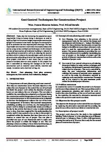
Real-time dynamic substructuring (RTDS) is the state of the art hybrid method for the dynamic testing of complex engineering structures (Blakeborough et al., 2001). This technique involves creating a hybrid model of the entire structure by combining an experimental part, the substructure, which is usually difficult to model (e.g. due to nonlinearities that render numerical modelling uncertain) and the remainder of the structure, often linear and modelled numerically. In order to emulate the dynamic behaviour of the complete original structure the dynamics of the two substructures as well as their reciprocal interactions must be reproduced accurately in real-time. In a typical substructuring test, the interface displacement is calculated by the numerical model(s) and passed to the substructuring controller which generates the suitable control signal to drive the actuator. The actuator in turn will impose this displacement on the physical substructure and the resulting forces will be fed back to the numerical model forming a bi-directional coupling. The numerical model uses the measured feedback forces together with the external excitation to calculate the desired interface displacement for the next time step. This working principle is illustrated in Figure 1. Apply the experimentally measured forces to the numerical substructure(s)
External Excitation
This cycle must
Physical Substructure
be performed
Numerical Substructure
Measure the resulting forces and actual displacements on the test specimen
and completed
force fed back from the physical substructure and the external excitation are used to calculate the desired interface displacement for the next time step
within each sampling time
Command actuator(s) to apply dispalcement(s) to the physical substructure
Fig. 1. The working principle of real-time dynamic Substructuring. Conducting the substructuring tests in real-time has the advantage of allowing direct measurement of nonlinear dynamic parameters especially for rate dependent components particularly dampers (Wagg et al., 2001).
However, due to the experimental nature of the technique and due primarily to the mechanical characteristics of the actuation devices which cannot respond instantaneously, the presence of time delays is inevitable. In some situations this delay may be so small as to be negligible, but it is the typical situation in real-time substructuring that it is large enough to have a significant influence on the overall dynamics of the controlled system and in certain cases can lead to instability (Kyrychko et al., 2007). To date, most substructuring work has considered tests using a single actuator, which has been developed well beyond the proof of concept stage (Blakeborough et al., 2001; Darby et al., 2001). Multi-actuator substructuring can also be employed in tests where more than one degree of freedom needs to be represented at the interface (Wallace et al., 2005a, b). The success of the RTDS tests depends heavily on the control and compensation of the actuator(s) (Wallace et al., 2005a, b, 2007). In fact, the essence of the technique is to compensate for the actuator dynamics in such a way that emulation of the complete original system is achieved. In other words, if the actuator can be reliably controlled, the actual displacements imposed by the actuator on the physical substructure will match the demanded displacements from the control system, which will result in the physical substructure responding in the correct way and the measured forces in the feedback loop will in turn be correct. In order to achieve emulation at the interface conditions, a range of control techniques and compensation schemes could be considered depending on the actual application. The current work is based on a project to carry out RTDS tests on a simplified wing model consisting of a 3D cantilever beam with the ultimate aim to conduct RTDS on complex wing tip mechanisms such as hinged morphing winglets by combing wind tunnel testing with RTDS. The main results presented in this paper will focus on identifying delays and characterising their effect on the real-time substructuring algorithm. This paper will also discuss how the RTDS control problem is
fundamentally different from the standard control counterpart and will report preliminary control work done on a multi-axis experimental rig commissioned specifically for the current RTDS application. 2.
RTDS FOR AEROSPACE APPLICATIONS
Novel wing designs such as winglets (the canted wing tips seen on many newer airliners) have been a major research area and much work has been ongoing on their design, test and development to understand their true effectiveness in improving primarily the aerodynamics of the wing as well as the overall performance of the entire aircraft. Research conducted at the University of Bristol focuses on designing morphing winglets which is a novel advance in the structural dynamics community. RTDS is considered to be an effective testing strategy to understand their dynamic behaviour without isolation from the rest of the wing for a better understanding of the complete wing response. Applying RTDS to an aircraft wing entails the consideration of both the structural response as well as the aerodynamics, which implies combining the described structure-to-structure hybrid approach with an additional aerodynamic forcing provided by a wind tunnel facility. This work will establish a proof of concept of RTDS for an aerospace application.
Where Fext and My are the total generated forces (including inertial forces) and the corresponding moments acting on the wing, E is the Young’s modulus of elasticity, I is the moment of inertia, m is the wing mass, G is the shear modulus of elasticity and J is the torsional constant, xea and xcg respectively are the distance of the elastic and inertial axis from the wing leading edge. This mathematical modelling captures the key dynamic behaviour of the wing defined primarily by 2DoF and helps the development of a corresponding reduced order model. At the numerical-experimental interface, the cross-section of the beam is assumed to remains plane (i.e. insignificant distortions) and the numerical model of the wing to be substructured will consider a linear modal decomposition of the beam model to allow both bending and torsion modes to be included. The following figure illustrates a cantilever beam in a pure bending mode. X
Z
w
2.1 Structural substructuring The current research will consider initially a simplified wing model consisting of a 3D cantilever beam representing a standard aircraft wing model. For the first stage of substructuring, the structural equations of motion governing a cantilever wing have been derived using the application of Lagrange’s energy method. The development of these equations is based on the assumption that the elastic axes is the reference for measuring the angular deflection α (y, t) for the pitch mode, and the heave displacement w (y, t) for the bending mode (Bisplinghoff et al., 1955 ). X
X
Leading egde w
Inertial Axis
X cg
Z
0
Xea
Elastic Axis
Fig. 2. The adopted axis definition and sign convention for a cantilever wing. For a general wing where the inertial and elastic axis do not coincide (as shown in Fig. 2), the structural equations of motion governing the two degrees of freedom in pitch α , and heave w , are given by: m Iy
∂ 2α ∂4w ∂2w + EI z 4 + mc( xea − xcg ) 2 = Fext ∂t ∂y ∂t 2
∂ 2α ∂ ∂α ∂2w − (GJ ) + mc ( xea − xcg ) 2 = M y ∂t 2 ∂y ∂y ∂t
(1) (2)
Y
Fig.3. 3D cantilever beam representing a simplified wing model in pure bending mode 2.2 Aerodynamic substructuring Introducing the aerodynamics into the substructuring strategy is the ultimate objective of the current work, and to the authors knowledge this has never been previously accomplished. The conceptual implementation is to divide the wing span into two parts: (i) the in-board part modelled numerically (including aerodynamic forcing), and (ii) the outboard portion (potentially including the morphing winglet) tested physically in a low speed wind tunnel. A significant future challenge in this work is to transfer the effect of the pressures and velocities at the interface between the two parts of the wing section to emulate the complete wing aerodynamic response, in a similar way to the emulation of the structural response through the control of actuators. The current focus is on developing a suitable testing platform which can act as the transfer system for the structure-to-structure substructuring for the simplified wing model. This in itself presents a significant challenge, as most substructuring work to date has been uni-axial, even if multi-degree-offreedom (Wallace et al., 2006a). As a result this paper will present results from the design and commissioning stages of the testing platform. From a control point of view, it is envisaged that the aerodynamic substructuring will introduce interesting control problems in term of both robustness and performance when taking into account turbulence in
wind tunnel for instance. This is beyond the scope of the current paper. 3.
THE MULTI-AXIS EXPERIEMNTAL RIG
The multi-axis experimental rig was designed to provide a test-bed platform for the RTDS tests. It acts as the transfer system between the numerical and physical substructures and consists of a two degree-offreedom (2DoF) moving platform powered by two linear electro-mechanical actuators which are mounted in parallel as shown in Fig. 4. The physical substructure (the wing-tip/aileron/winglet) can be mounted on the test rig via special interface arrangements. A key design principle of the rig was to keep the mass (and hence the inertia) of the moving platform as low as possible to ease the real-time implementation as well as the additional loading constraints on the controller-actuators while in operation.
To conduct the real-time substructuring tests, a dSpace DS1104 Controller Board was used along with ControlDesk which is fully integrated into the block diagram based modelling tool MATLAB/Simulink and used for online analysis and control of the experiments. Each electro-mechanical actuator is driven by a separate servo motor and has a maximum force capacity of 2.5kN and a maximum frequency range of up to 12Hz. For the aerodynamic substructuring the rig will be positioned next to the wind tunnel with the wing tip specimen projecting into the tunnel via a removable side-wall. The control of this experimental rig is very critical to the success of the substructuring tests. Once the control is established for the 2DoF, the rig could be used for other applications ranging from dynamic load excitations, active vibration control as well as other aerospace applications such as flutter suppression. This will establish a functional versatility for the rig. 4.
Fig. 4. The multi-axis experimental rig setup in the lab The rig has 2DoF that are defined in the vertical plane by a vertical translation (heave) and a rotational motion (Pitch). The heave motion will be excited by a parallel in-phase action of the actuators while the roll mode will be obtained by differential (parallel out-of-phase) actuation. Since the rig will operate in displacement control, a Linear-Variable- Differential-Transducer (LVDT) is used to measure the displacement of each actuator. The kinematics of this experimental rig depends primarily on the distance between the two actuators, their lengths, their orientation, as well as their operating stroke range. The design has accounted for the distance between the two actuators (along the length of the platform) to be changed according to the testing requirements. In percentage format for the spacing with increasing sensitivity inward
THE CONTROL STRATEGY FOR RTDS
The essence of the RTDS technique is the emulation of the complete original system. This is achieved by controlling and compensating for any unwanted dynamics at the interface between the numerical and experimental substructures such that the original system dynamics are accurately reproduced. The success of the emulation process depends heavily on the effectiveness of the employed control techniques (Wallace et al., 2005a, b, 2007). From a control point of view, there is a fundamental difference between a standard control problem and that of RTDS. In substructuring tests the reference signal (the control demand) for the actuator is not known at the start of each time step, but must be calculated within the numerical model during each time interval (Darby et al., 2001). This control signal is in fact compound and originated from; firstly a well known part made from the numerical model and the external excitation, and secondly, the unknown part which is the measured forces on the substructure itself. The real-time implementation of the technique implies the presence of time delays that are inevitable due to the mechanical characteristics of the actuators being unable to respond instantaneously to a state change in demand (Wallace et al., 2005a, b). In effect, actuators constitute a critical part in the substructuring algorithm and the success of any RTDS test is critically dependent on the effectiveness of their control. The aim of the RTDS control algorithm is to compensate for the actuator delay to ultimately achieve synchronisation between the desired interface displacement of the numerical models, (z), and the actual position of the actuator, (x) as shown in Fig. 5. Computational part interface displacements
Numerical substructure
outer-loop compensator
actual
displacement
x*
Z External Excitation
Experimental part target
inner-loop controller
displacement
Actuators Rig & Transducers
displacement feedback
Outer loop: force feedback
x
Physical substructure
Since the control signal contains a measurement element based on a feedback force, there will always be an additional source of delay (filtering and signal conditioning) and unmodelled dynamics (noise) to the substructuring algorithm. However, these effects will not be as significantly detriment to the stability of the system as the actuator time delay, but will certainly affect to some extent the accuracy and robustness of the substructuring control. The RTDS control problem could be tackled in two complementary stages. Firstly, a basic tracking control problem, which is in the current application undertaken by a Proportional plus Integral control (P+I) such that a repeatable dynamic response from the actuator could be achieved. The controller together with the actuator constitutes the inner loop as shown in Fig. 5. The second control task is to implement a delay compensation technique to eliminate the time delay introduced by the actuator. This compensation scheme will be established in the outer loop and will be directly related to both the numerical model and the feedback force measurement. Therefore, any discrepancies in the control of the actuator will directly affect the feedback force measurement and ultimately the numerical model as well. The first stage of the control work will consider a reference signal being a simple sinusoidal excitation with a compensation scheme of a constant forward prediction algorithm based on a fourth order polynomial extrapolation which is fully explained in details in (Horiuchi, T, 1999). Once the delay compensation is established for each actuator, the next stage of the control work will consider a reference signal determined directly from the corresponding numerical substructure of each actuator. 4.1 Effect of Delay on the Substructuring Algorithm The main particularity of the RTDS technique is its direct dependence on the control of the actuators (Kyrychko et al., 2006b). A small delay in the actuator response introduces a corresponding error in the feedback force vector which can be thought of as adding negative damping to the system (Wallace et al., 2005a). This discrepancy has the effect of first reducing the accuracy of the numerical model compared to the emulated system until the magnitude of the synchronisation delay increases to a point where the damping of the overall system changes sign and become negative. At this point, instability of the substructuring algorithm is observed and is characterized by the onset of oscillations with exponential growth (Wallace et al., 2005b). Actuators time delays with their detriment effect on the stability of the substructuring process have inspired a wide range of research activities (Gawthrop et al., 2007) and many delay compensation schemes (Wallace et al., 2005a,b) and stability analysis techniques (Kyrychko et al., 2007) are becoming focal research topics in RTDS. The focus of the current control studies will be mainly on a delay compensation technique based on a fourth order polynomial extrapolation using forward prediction method and synchronisation theory (Wallace
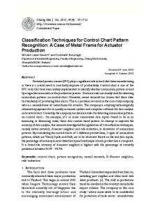
et al., 2006a). This technique helps in minimising the delays present in the system by forward predicting the control signal at each time step. 4.2 The RTDS Inner Loop Control This is where a tracking control scheme will be established for each actuator. The time delay associated with each of the actuators will be identified through a closed loop system identification process. System identification was conducted mainly to determine the actuator transfer function from contiguous input-output data. The signal was defined in terms of amplitude and time and the identification process is done in the frequency domain. A constant amplitude sine sweep from 0 to 8Hz as well as a constant sinusoid input for different amplitude cases were considered. Amplitude accuracy and delay magnitude were the two main parameters considered in the analysis. A closed control loop is applied with a linear Proportional plus Integral control (P+I) that acts as the inner loop controller for the substructuring algorithm. Several controller gain settings were tested and the results showed that the delay magnitude depends heavily on the selected proportional gain values while the amplitude accuracy depends on the integral gain setting. Over the operating frequency range from 0 to 8Hz, a proportional gain value of eight (Kp = 8) was chosen to be the optimum one while the integral gain (Ki) changed according to both the frequency and amplitude of excitation. The MATLAB function oe(Output Error) was used with an attempt to predict the best fitted model from a polynomial based output error algorithm. The approximate transfer functions for the two actuators via Laplace transform were postulated to be ( Yact1 ( s ) = 48/(s + 47)) and ( Yact 2 ( s ) = 49/(s + 43)) with the corresponding fixed time delay of approximately (0.020s) and (0.021s) respectively. This time delay is easily observed when comparing the target displacement (x*) and that measured with the LVDT (x). A typical response of one of the actuators being sinusoidally controlled is shown in Fig. 6. 20
Displacement Amplitude (mm)
Fig.5. The RTDS standard block diagram.
Response Demand
15 10 5 0 -5 -10 -15 -20 10
10.1
10.2
10.3
10.4
10.5
Time (s)
Fig.6. Position tracking response of the actuator being sinusoidally controlled at 4Hz. These delays which are mainly attributed to the mechanical characteristic of the actuators will act as a negative damping in the system and will cause loss
of accuracy and in certain cases loss of stability (Kyrychko et al., 2006b). An additional control technique is therefore needed to compensate for these time delays to guarantee stability for the system. 4.3 Delay Compensation and Synchronisation Theory When dealing with delay compensation within the framework of RTDS, synchronisation theory is sought as a powerful complementary tool to assess the effectiveness of the employed control algorithm. This assessment is done in a post-process procedure by plotting the actual versus the desired response in a 2D space vector (Wallace et al., 2005a, b). A typical synchronisation subspace plot showing the actuator performance at different excitation frequencies is shown in Fig.7. Delay magnitude and amplitude accuracy are the two determining components of accuracy from the plot. Perfect synchronisation is represented by a diagonal straight line with maxima and minima of the reference signal as shown by a dashed line in Fig.7. 20
Ideal line with zero delay
Response Amplitude (mm)
15
increased delay magnitude
10 5 0 -5
4.4 Frequency Effects and the Real-Time Constraint The operational frequency range is a very important consideration especially in RTDS applications where the tests aim typically for fast control algorithm implementation. For a typical substructuring test, the actuators are required to be able to operate reliably within a specified frequency range in order to meet the fast real-time constraints. Although the actuators employed for the current tests have a limited range of operational frequency (up to 8 Hz), the implemented control and compensation technique were shown to be effective with a well predictable performance at least for the first stage of the control work. At an advanced stage of the research work, the acquisition of actuators with higher frequency specification is being envisaged. 4.5 The Interface Control and Coupling
-10 -15 -20 -20
-15
-10
-5
0
5
10
15
20
Demand Amplitude (mm)
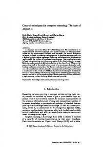
Fig. 7. Synchronisation subspace plot for excitation frequencies of 1 and 5Hz. Any reduction in synchronisation is illustrated by a deviation from this idealized line and this is manifested by transforming the idealized straight line into an ellipse; the greater the delay, the larger the width of the minor axis of the ellipse, with the change being proportional to the delay magnitude as illustrated in Fig. 7. The results shown here considered a simple proportional controller to demonstrate how amplitude accuracy was degraded with increasing frequency which is manifested by a change in the angular orientation of the plot. In order to minimise this delay, a compensation technique was implemented by forward predicting the control signal. Typical results are shown in Fig. 8. 10 8
Response Amplitude (mm)
This is achieved by sinusoidally (P+I) controlling the actuator at an excitation frequency of 8 Hz with a constant forward prediction compensation. Overall, the results of the forward predicting the control signal showed a remarkably good synchronisation with a reduced delay, resulting in a well predictable performance and hence stability for the substructuring algorithm once the outer loop is established.
6
delay magnitude
minimised delay
4 2 0 -2
It is worth noting that for the current RTDS application, the control and compensation work involves the whole experimental rig and not just the actuators dynamics. As a matter of a fact, both the inertia of the moving platform as well as the viscous damping in the bearing system have a direct contribution in the magnitude of delays identified in the system. For instance, as the excitation frequency is increased, the viscous damping (being proportional to the velocity of the moving platform) will increase accordingly resulting in an additional latency in the system. Controlling this multi-axis rig in real-time for the 2DoF (heave and pitch) at the interface between the numerical and experimental substructures presents a significant control challenge, as most substructuring work done to date has been uni-axial even if multidegree-of-freedom (Wallace et al., 2005a, b, 2007). Synchronous tracking control for the heave mode was established for the parallel actuation with a forward prediction compensation scheme. The control of the second motion mode (pitch) is of an going work. Ongoing work considers also reducing the mass (and hence the inertia) of the upper platform for improved operational frequency and performance. This will also help in relieving the loading constraints on the employed actuators.
-4
4.6 The Substructuring interface Emulation Loop
-6 -8 -10 -10
-8
-6
-4
-2
0
2
4
6
8
10
Demand Amplitude (mm)
Fig. 8. Synchronisation subspace plot illustrating the effectiveness of the compensation at 8Hz.
This is where the full RTDS control loop will be established with the reference signal for each actuator being determined within its corresponding numerical substructure at each time step. The control
problem at this stage will be more difficult with the challenge to achieve synchronisation between the desired interface displacement of the numerical models, z, and the actual position of the actuator, x as shown in Fig.5. The delay compensation scheme must be capable of dealing with the discrepancies in the control algorithm due to the propagation of the time delay in the feedback force. Other control challenges other than the time delay, will be numerical errors within the numerical model as well as unmodelled dynamics (noise for instance) in the feedback path. This will compromise the accuracy of the control algorithm add will inspire control studies related to robustness as well as performance in general. 5.
CONCLUSIONS AND FUTURE WORK
The RTDS has been described for an aerospace application with a 3D cantilever beam representing a standard aircraft wing to be the emulated system for the proof-of-concept implementation. It was illustrated how the substructuring control problem is fundamentally different from the standard control counterpart and how the RTDS is critically dependant on the effectiveness of the actuators control. Issues related to real-time control were the main focus of this paper with the main challenge being the actuators time delay induced instability. A forward prediction delay compensation technique based on a fourth order polynomial extrapolation was used with synchronisation theory and showed good results in terms of reduced delay magnitude and improved control accuracy. Besides, it was discussed how the real-time control for the full RTDS implementation will be more challenging due to a feedback force element with additional discrepancies and unmodelled dynamics. Adaptive compensation schemes as well as nonlinear dynamic inversion method are being considered for future control work. These techniques will account for the time delay variation over a wider frequency range and will also allow for control implementations at a varying frequency which is advantageous for the current aerospace application. A multi-axis experimental rig commissioned specifically for the current substructuring application was presented with its working principle to be used as a test bed platform for current RTDS studies. With its kinematically coupled nature, it was discussed that this rig will inspire new real-time control techniques for both performance and stability within the framework of RTDS tests. ACKNOWLEDGEMENTS The author, Meriem Allouache gratefully acknowledges the awarded sponsorship from the Algerian ministry of higher education. D. J. Wagg is supported by an EPSRC Advanced Research Fellowship.
REFERENCES Blakeborough, A., A. P. Darby and D. M. Williams. (2001). The development of real-time substructure testing. Philosophical Transactions of the Royal Society of London A, 359,1869–189. Darby, A. P., Blakeborough, A. and Williams, M. S. (2001). Improved control algorithm for real-time substructure testing. Earthquake Eng. Struct. Dyn. 30, 431–448. (doi:10.1002/eqe.18.) Bisplinghoff R.L., Raymond L., Halfman.(1955). Aeroelasticity. Addison Wesley Publishing Company Inc. Horiuchi, T., Inoue, M., Konno, T., and Namita, Y., (1999). Real-time hybrid experimental system with actuator delay compensation and its application to a piping system with energy absorber. Earthquake Engineering and Structural Dynamics, 28, pp. 1121–1141. Gawthrop, P.J., M.I. Wallace, S.A. Neild and Wagg (2007). Robust real-time substructuring techniques for under-damped systems. Structural Control & Health Monitoring 14(4), 591–608. Kyrychko, Y., S. J. Hogan, A. Gonzalez-Buelga and D. J. Wagg (2007). Modelling real-time dynamic substructuring using partial delay differential equations. Proc. Roy. Soc. A. 463(2082),1509–1523. Kyrychko, Y. N., K. B. Blyuss, A. Gonzalez-Buelga, S. J. Hogan, & D.J. Wagg (2006). Real-time dynamic substructuring in a coupled oscillator-pendulum system. Proceedings of the Royal Society A, 462(2068):1271–1294. Wagg, D.J. and D.P. Stoten (2001). Substructuring of dynamical systems via the adaptive minimal control synthesis algorithm. Earthquake Engineering & Structural Dynamics, 30, 865–877. Wallace, M.I., D.J.Wagg, S. A. Neild, P. C. Bunnis, N. A. Lieven and A. J. Crewe. (2007). Testing coupled rotor blade-lag damper vibration dynamics using realtime dynamic substructuring. Journal of Sound & Vibration, 307,737-754. Wallace, M.I., D.J. Wagg, and S. A. Neild (2005a). An adaptive polynomial based forward prediction algorithm for multi-actuator real-time dynamic substructuring. Proceedings of the Royal Society A. 461(2064),3807–3826. Wallace, M.I., J. Sieber, S. A. Neild, D.J.Wagg, and B. Krauskopf (2005b). Stability analysis of real-time dynamic substructuring using delay differential equation models. Earthquake Engineering & Structural Dynamics, 34(15), 1817-1832.