SAE TECHNICAL PAPER SERIES
2006-01-0840
Controller Integrity in Automotive Failsafe System Architectures Padma Sundaram and Joseph G. D’Ambrosio Delphi Corporation
Reprinted From: Safety Critical Systems (SP-2029)
2006 SAE World Congress Detroit, Michigan April 3-6, 2006 400 Commonwealth Drive, Warrendale, PA 15096-0001 U.S.A. Tel: (724) 776-4841 Fax: (724) 776-5760 Web: www.sae.org
The Engineering Meetings Board has approved this paper for publication. It has successfully completed SAE's peer review process under the supervision of the session organizer. This process requires a minimum of three (3) reviews by industry experts. All rights reserved. No part of this publication may be reproduced, stored in a retrieval system, or transmitted, in any form or by any means, electronic, mechanical, photocopying, recording, or otherwise, without the prior written permission of SAE. For permission and licensing requests contact: SAE Permissions 400 Commonwealth Drive Warrendale, PA 15096-0001-USA Email:
[email protected] Tel: 724-772-4028 Fax: 724-776-3036
For multiple print copies contact: SAE Customer Service Tel: 877-606-7323 (inside USA and Canada) Tel: 724-776-4970 (outside USA) Fax: 724-776-0790 Email:
[email protected] ISSN 0148-7191 Copyright © 2006 SAE International Positions and opinions advanced in this paper are those of the author(s) and not necessarily those of SAE. The author is solely responsible for the content of the paper. A process is available by which discussions will be printed with the paper if it is published in SAE Transactions. Persons wishing to submit papers to be considered for presentation or publication by SAE should send the manuscript or a 300 word abstract to Secretary, Engineering Meetings Board, SAE. Printed in USA
2006-01-0840
Controller Integrity in Automotive Failsafe System Architectures Padma Sundaram and Joseph G. D’Ambrosio Delphi Corporation Copyright © 2006 SAE International
ABSTRACT Embedded controllers and digital signal processors are increasingly being used in automotive safety critical control systems. Controller integrity is a significant concern in these systems. Over the past decade, several techniques have been published about controller safety and integrity verification. These techniques include: single processor with watchdog, dual processors, dual core processor, and asymmetric processor (intelligent watchdog). Each of these techniques have benefits, however, many new nondistributed safety-critical systems are applying the asymmetric processor technique to help verify controller integrity. This paper discusses an overview of five controller integrity techniques, and then provides a detailed discussion of an asymmetric processor approach. This paper presents two different options within the asymmetric processor approach.
INTRODUCTION Over the last decade there has been rapid growth of automotive safety-critical systems controlled by embedded software. Embedded controllers are used to achieve enhancements in vehicle comfort, feel, fuel efficiency, and safety. For those systems that are safety critical, software is handling key decision making related to controlling essential vehicle functions such as steering and braking independent of the driver. Although many of these systems help provide significant improvements in vehicle safety, potential unexpected interactions among the software, the hardware, and the environment could lead to potentially hazardous situations. Software is a logical construct, and in isolation may not cause harm [1]. However, the components or systems that are controlled by software logic may have the potential to cause harm if not controlled correctly. Since software resides in a controller, any potential controller failure could affect the execution of the software, possibly leading to undesired system behavior. Thus, helping confirm controller integrity also helps confirm software and system safety.
By identifying potential controller hardware failure modes, it is possible to understand their effects on software execution and develop diagnostic techniques to detect and handle their occurrences. Some of the common controller hardware failures include memory cell failures in either the code space or variable space, Central Processing Unit (CPU) failures (Arithmetic Logic Unit (ALU), registers, op-codes) or peripheral failures (Analog to Digital Converter (ADC), Input Output (IO) ports etc). Memory cell failures can cause conditions where the software jumps to the end of a routine abruptly without completely executing the desired functionality. Interrupt failure modes like return of incorrect priority and failure to return, thereby blocking lower priority interrupts, can also be caused by memory corruption. CPU failures like ALU errors can cause incorrect calculations in the software potentially leading to incorrect output states. Peripheral failures like ADC and IO port failures can impact incoming or outgoing signals of the controller thus potentially impacting system behavior. Generally, a controller integrity strategy selected for a specific system is such that it satisfies system safety requirements and does not compromise system performance requirements. In this paper, we review existing controller integrity techniques that have been applied in the automotive industry. Each of these techniques has benefits; however, many new nondistributed safety-critical systems are applying the asymmetric processor technique to help verify controller integrity. The remaining portion of the paper expands on the asymmetric processor approach. The different options that are possible within the asymmetric processor approach are briefly discussed. By combining these external controller diagnostics performed by a secondary controller, with complimenting primary controller’s self-diagnostics, high confidence in controller integrity can be achieved.
OVERVIEW OF AUTOMOTIVE FAILSAFE CONTROLLER STRATEGIES Over the past two decades, several strategies have been developed to satisfy the failsafe requirements of automotive embedded systems. For safety critical
systems, the controller should provide deterministic behavior under conditions of failure. Typical criteria for selecting a specific strategy include: Primary Criteria 1. Must satisfy system safety requirements. Failure management provided within the system safe response times. Meaning system transitioned to a safe state within the required safe fault response time.
To help verify high integrity operation for this failsafe controller strategy, the controller may implement internal hardware protection techniques (e.g., error detection circuits or error detection and correction circuits), or a significant portion of the processors throughput could be dedicated to self-checking diagnostics. For this approach, controller throughput and memory size must be adequate to handle both the control application and the self-checking diagnostics. By carefully combining hardware and software protection mechanisms, it may be possible to achieve high confidence in controller integrity using this controller strategy.
Secondary criteria 1. Level of independent checking provided 2. Performance
In summary, this controller strategy may be best for those applications where significant processor resources (throughput and memory) can be dedicated to selfchecking diagnostics.
3. Technology availability 4. Development effort Generally system design is influenced by system safety requirements. Safety requirements provide guidance in the selection of the safety approach for the controller. Safety requirements prescribe the failure management and fault response needs under failure conditions of the system. In software intensive systems, failure management is typically handled by the controller. Failure management process requires that critical faults are detected and handled within the system’s safe fault response time. This time is defined as the time that is available for the system to detect a critical fault and transition to a safe state before the fault could lead to a potentially undesirable system condition. This prescription of safe fault response times can guide the choice of an appropriate processor that can handle the safe fault response time requirements without compromising system performance needs. In the following paragraphs the different approaches for fail-safe controller architectures are discussed, highlighting the benefits of each approach.
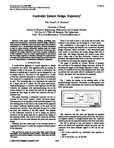
SINGLE-CONTROLLER STRATEGY A single-controller failsafe strategy, as shown in Figure 1, consists of a single controller executing the target application software and self-checking diagnostics, along with a simple watchdog circuit. The watchdog provides a limited-level of independent checking of the primary processor. A watchdog typically requires the controller to periodically reset or toggle the watchdog. If such a reset is not performed within some time interval, the controller will reset itself. Thus, the watchdog detects conditions where the execution of software on the controller has hung up (e.g., endless loop) or where specified program flow has been interrupted (unwanted branch). A simple watchdog cannot detect other types of potential failures, such as incorrect output calculations.
Inputs
Single ECU Architecture
Output
Figure 1: Single-controller strategy
SYMMETRIC-CONTROLLER STRATEGY In this controller strategy, two symmetrical (identical) controllers are used for crosschecking controller operations (see Figure 2). Each controller executes the same application based on the same inputs. At specific time points, the controllers exchange key calculations and compare the results. If either controller detects a mis-compare, the system is assumed to have a fault. By checking for time-outs in communications, all the faults detected by a simple watchdog are guaranteed to be detected by this approach as well. This strategy provides good coverage of hardware faults with minimal effort devoted to developing self-checking diagnostics. Any random hardware failure that influences key calculations can be detected (other than those failures that lead to common cause failures in both controllers). As a consequence, extensive self-checking diagnostics to detect random controller failures are not explicitly required. Software errors can also be detected if a diverse programming approach is followed, however, this typically requires significant investment in software development and verification activities. One significant technical issue in implementing this controller strategy is maintaining synchronization between the two processors. Since each processor has its own clock, the two processors may not run at the exact same clock frequency, and care must be given to help confirm that the calculations being compared were performed at the same time. If comparisons are made
between calculations based on different inputs (due to synchronization issues), two fully functional processors could produce calculations that mis-compare. If a design team is willing to invest in the additional costs associated with implementing a time-triggered architecture, the global clock synchronization services these architectures provide can help solve this problem. In summary, the symmetric controller strategy provides a high-level of independent checking of the hardware. Depending on the level of synchronization, the fault detection time achievable by independent hardware checks may be fast. Extensive self-checking diagnostics are likely not required, reducing the demand on software development, processor throughput and memory requirements. The major limitations of the approach include the need to synchronize processors and the cost, size, power, etc. of adding a second processor.
Inputs Dual CPU
CPU
Inputs
Main Controller
immediately, but detection time of all types of controller failures in general depends on the execution time of the self-checking diagnostics that must be implemented. Given that non-CPU self-checking diagnostics are still required, software development effort, processor throughput and memory requirements are potentially less than that required by a single controller approach, but more than that required by a symmetric controller approach. One significant issue with a dual-core strategy is the availability of the technology: there are a limited number of processors that implement a dual core strategy, and as a consequence this strategy may not be an option depending on commercial issues.
Redundant Secondary Main
CPU
Output
Figure 3: Dual CPU strategy
ASYMMETRIC-CONTROLLER STRATEGY Figure 2: Symmetric controller strategy
DUAL-CORE CONTROLLER STRATEGY In this controller strategy, the primary processor has a duplicate CPU (see Figure 3). The two CPUs receive the same data and control inputs, and the outputs of the CPUs are compared to detect discrepancies. This approach provides high coverage of random hardware failures that can occur in the central processing unit. Additional self-checking diagnostics (e.g., memory checks) along with a simple watchdog can be implemented to provide a high-integrity controller [2]. Typically, an overall bootstrapping strategy is followed to check the processor’s resources for correct operation. Given that all CPU failures can be detected, the CPU is assumed to be reliable, and additional self-checking diagnostics rely on the correct operation of the CPU, and begin to verify correct operation of other controller resources. As each additional resource is tested for correct functionality, it then too can be trusted by the remaining diagnostics to be reliable. This controller strategy can provide a higher level of independent checking than is provided by a single controller strategy, without the potential size, cost, etc. penalties associated with a symmetric processor strategy. CPU related failures can be detected
In this controller strategy, a simple, low cost secondary processor (or ASIC) is used as an intelligent watchdog to check the primary processor (see Figure 4). The strategy has the potential to provide a high level of independent checking at a lower cost compared to the symmetric processor strategy. Often, the secondary processor is an off-the-shelf purchased controller instead of an ASIC, as custom ASICs typically require more design time and may have higher cost depending on the volume produced. To help detect hardware failures, the secondary processor periodically requests diagnostic checks by the primary processor to verify the integrity of the primary processor. This communication can occur either via a discrete line, or a serial communication line like for example, a Serial Peripheral Interface (SPI). Depending upon the design of the diagnostics architecture, it is possible to achieve good diagnostic coverage of the different sections of the processor (e.g., CPU, Memory, and Peripherals). Since an external processor is verifying the primary processor, confidence in the controller’s integrity can be higher than that provided by self-checking diagnostics.
Inputs
Main Controller
Output
Asymmetric Processor
a dedicated wire is run from the second controller to the primary controller and hard wired to a local independent disable circuit. For the second option, the primary’s local network communication controller has the ability to independently recognize the shutdown command and has the ability to activate a local disable circuit if such a command is received. The selection of the specific approach for a distributedcontroller strategy depends on a number of factors, including: available network bandwidth, fault response times, available controller throughput, synchronization issues, and controller sourcing decisions (i.e., single supplier vs. multiple suppliers).
Figure 4: Asymmetric processor strategy
Bus DISTRIBUTED-CONTROLLER STRATEGY In this controller strategy, the primary controller is checked by another networked controller (see Figure 5). This approach supports a wide range of diagnostic options, including:
Controller 2
Controller 1
1. Independent redundant algorithm execution with voting.
Shut Down Command
2. Independent primary processor state of health checks.
Figure 5: Distributed-controller strategy
The first option is very similar to the symmetric-controller strategy. Sensor input signals for the primary processor along with algorithm results are sent to a second controller on the network. The second controller executes the same algorithm as the primary controller, and compares its results against those of the primary controller. If there is a discrepancy, the second controller disables the primary controller (for failsafe applications). The second option is very similar to the asymmetriccontroller strategy. The primary controller receives a seed (i.e., input) from a second controller on the network. The primary controller performs a sequence of calculations, and returns the result to the second controller. The second controller compares the result with a pre-computed value, and if there is a discrepancy, the second controller disables the primary controller. Both options and other variations depend on the ability of the second controller to disable the primary controller. If the primary controller is faulted, it may not be possible to rely on sending a shutdown command from the second controller to the primary over the network, because there is no guarantee that the faulted primary controller will be able to process the shutdown command. As a consequence, an independent means of shutting down the primary controller is needed. Two possible options for shutting down the primary controller include: dedicated shutdown line, and shutdown by local network controller. For the first option,
Recently, a trend for implementing the asymmetriccontroller strategy has begun to emerge for nondistributed controlled steering and braking applications. Early applications of the symmetric-controller strategy by automotive suppliers were abandoned, due in part to the difficulties in achieving tight processor synchronization and component cost. The dual-core strategy has seen significant application in steering and braking products, but this approach has not been possible for newer systems requiring more powerful processors, as dual core technology has not been available for these processor families. The single-controller strategy has been applied to occupant protection systems, as these systems have the ability to dedicate a significant amount of controller throughput to diagnostic checking, but this approach has not seen much application on controlled steering and braking products. As a consequence of the above, many new controlled steering and braking systems implement an asymmetric strategy. As new technologies such as time-triggered networks and AUTOSAR [3] become practical for production applications, the distributed-controller strategy may become dominant. However, as previously discussed, much of the asymmetric strategy can be implemented within the context of the distributed strategy, and thus the asymmetric approach has significant value now and possibly in the future as well. In this paper, asymmetric strategy appropriate for automotive domain applications is discussed. The paper
highlights the different options within the asymmetric controller approach that can be implemented to achieve high ECU coverage, thus providing increased confidence in the primary processor’s integrity.
ASYMMETRIC CONTROLLER APPROACH Before the asymmetric approach is discussed, fundamentals of controller integrity checks are discussed. Figure 6, shows a typical high level structure of a processor. At a high level, typical controllers can be viewed as containing three major subsystems: 1. Central Processing Unit (CPU)
processor for controller integrity verification are discussed. First, a basic asymmetric approach which is a bootstrap approach based on independent CPU verification, is discussed. Following that an extended approach for independent verification of different controller components is presented. BASIC ASYMMETRIC PROCESSOR APPROACH In a basic asymmetric processor approach, the secondary processor is primarily used to verify the integrity of the primary processor’s CPU. Figure 8 shows the general hardware layout of the basic Asymmetric approach.
2. Peripherals including input/output devices and 3. Memory subsystem The CPU includes data registers and data manipulators, which primarily include the ALU, the auxiliary registers, and the op-code/decode circuits, etc. Memory subsystem can include the RAM, FLASH, ROM, and EEPROM. Peripherals include the Timers, Event Managers, and Input/Output (I/O) subsystem. I/O subsystem can include peripherals like the Analog to Digital Converter (ADC), Controller Area Network (CAN), the Serial Peripheral Interface (SPI), Serial Communication Interface (SCI) etc [4,5]. Ensuring that the execution and control functions of the controller are healthy is the primary goal of any controller diagnostics approach. Once that is achieved, based on system safety requirements, the I/O and the memory subsystem of the controller may need to be verified either independently or by the primary CPU itself.
Figure 6: Typical processor components The fundamental benefit of the asymmetric approach is the independent verification of the primary controller integrity by a secondary processor. The extent of independent verification can vary depending upon system safety requirements. Typically the quality and the quantity of the independent verification checks are chosen to satisfy individual system safety requirements. In this paper two approaches of using the asymmetric
Figure 7: System architecture for a basic asymmetric approach In this approach, the primary processor represents the processor whose integrity is being verified. ASP represents the Asymmetric processor that cross-checks the primary controller’s CPU. The output controller represents any driver that controls the output from the primary. It could be a motor driver, a CAN controller or any power control circuit. The ASP physically resides on the same circuit board as the primary processor and continuously monitors the health of the primary processor’s CPU as well as itself through various diagnostics. It communicates to the primary processor via a serial communication interface like for example, the Serial Peripheral Interface (SPI). The ASP controls one input of the enable gate of the output controller. The primary processor controls the other input of the enable gate. Either the primary processor or the ASP can disable the output controller on detection that the other processor is not responding or functioning correctly and also in response to detection of any local faults within the processor. The output controller will be enabled only when both the primary processor and the ASP send an enable signal to the output controller. Both the processors establish communication during controller initialization following an exchange of key diagnostic data. Further on successful startup, the ASP continues to monitor the primary processor’s CPU health by exercising the different functions of the CPU during system runtime. In this approach the ASP provides increased confidence in the primary processor’s CPU. The primary processor utilizes the CPU to self-check
other parts of the controller including the memory and peripherals.
flag a fault condition (time out). This check will exercise the execution unit as well as the “Timer” functions within the processors [6].
EXTENDED ASYMMETRIC APPROACH Analog to Digital Converter (ADC) integrity verification The following sections discuss briefly some possible independent controller checks that can be performed by the asymmetric processor. Within an extended approach, the asymmetric controller can be used to independently check additional primary processor resources beyond the CPU. The specific amount of additional checking depends on a number of factors including: system safety requirements, processor capacity and throughput of the both the processors, communication throughput between the processors, and the amount of primary processor throughput available to support interactions between the two processors. The following are some of the checks that can be performed within the extended asymmetric approach.
Figure 8: System architecture for an extended asymmetric approach Integrity verification during system start up During system initialization, correct operation of both the primary controller and the ASP can be confirmed using both processors to query the other. The queries can include memory integrity checks, CPU checks and overall system fail safe operability check. For example one way to achieve this is as follows: The primary processor and the ASP can exchange their respective memory checksum results during power-up handshake for cross verification against a pre-stored value in their memory. This can provide independent check on the memory integrity of the primary processor and the ASP. The ASP sends back the status of the verification checks to the primary processor. In addition to this, the primary processor can be used to confirm that the ASP is capable of monitoring the primary processor during normal operation mode and vice versa. This approach exercises the failsafe operation of the entire system. The primary processor and the ASP will transition out of the initialization state after the successful completion of tasks pertaining to that state. Lack of response by either processor within a specific time during message exchanges, can result in either communication driver to
Sampling the same analog signals in both processors and comparing the sampled values can confirm the integrity of the ADC. The more ADC channels checked, the higher the confidence in ADC peripheral. This check requires achieving brief synchronization to sample the ADC signals at the same time. The sampled signal can be compared for any significant discrepancy which can signal problems with the ADC module within either of the processors. CPU verification using program execution sequence and completion check Software program flow monitoring can be embedded with a set of ALU calculations at specific points throughout the primary application program. This can confirm that the application executed in the proper sequence to completion. At the same time, program monitoring can also be used to exercise several components within the controller including the ALU, the addressing modes functions of the CPU, the event manager, and the clock function. By threading the program flow monitor through the sequence flow of the primary software program, including the interrupt service routines it is possible to detect any illegal invocations of interrupts or functions that were not intended to be executed by design. To implement this approach, the ASP is used to inject several checks into the primary processor periodically and to check the primary processor’s response. A fault is flagged if either processor fails to communicate within a specified time period or the ASP detects discrepancy in the primary’s response to its query. Based on system safety requirements and throughput availability, the program flow monitoring can be applied at different levels of abstraction of the primary software. Based on the inquiry received from the ASP, the primary software can recognize the specific task to be checked, and can activate the monitoring of that task. As part of the verification of CPU, the primary processor can also be used to verify the integrity of the ASP. This can be achieved by forcing the ASP to exercise the CPU functions as it performs verification of the primary processor’s responses to the queries. An example implementation of the program flow-monitoring algorithm is shown in Figure 9 below.
Implementing extensive monitoring of the primary processor using a secondary processor can be challenging in terms of development effort, throughput availability for diagnostics within both the processors and overall system performance requirements. The primary criterion is to choose techniques that can achieve balance of both functional safety requirements, and system performance requirements [7].
SUMMARY AND CONCLUSIONS
Figure 9: Example of program execution monitoring Peripheral configuration integrity verification Typically, the primary processor can have several peripherals like an Event manager (EVM), PIE Interrupt Manager, ADC, General Purpose Input-Output (GPIO), CAN, SPI, SCI, WATCHDOG etc. A peripheral’s mode of operation is based on the configuration of the associated control register. The ASP can be used to verify that the assigned peripheral configurations are not corrupted by comparing it against stored values in its memory.
This paper summarized briefly five different safety strategies for failsafe controller architectures. Primarily, choice of a safety strategy for controllers is guided by individual system safety requirements. The paper discussed a basic and an extended option within the asymmetric controller safety approach. The various controller safety functions discussed are designed to confirm the health of the different components of the processor, including the CPU, memory, peripherals etc. In automotive embedded control systems, the available throughput in the controller is to be shared by both the system application functions and the system safety functions. Achieving balance of both system safety and performance of these systems is critical in the success of the system design. Considering such limitations it is more desirable to have a reduced set of diagnostics that provides maximum coverage of utilized controller functions. By carefully combining independent controller verification diagnostics with complementing selfmonitoring diagnostics of a processor, high coverage of controller functions is possible, thus providing increased confidence in the integrity of controller outputs.
Application output sanity verification The objective of this diagnostic is to perform a high-level sanity check of the application output of the primary processor. This type of diagnostic has the potential to detect a wide-range of processor failure modes, because producing a correct output typically depends on the proper functioning of the CPU, the peripherals, and the memory. In essence both the control unit and execution unit of the processor must be healthy to produce consistent healthy output. A simplified version of the overall application function can be executed periodically in the asymmetric processor, with similar inputs as that provided to the application in the primary processor. The outputs of both the simplified application and the full application can be compared for sanity. The ability to implement this type of safety function depends on the availability of simplified logic of the primary application, the capacity and throughput of the ASP and the primary processor. In any controller safety approach, where a secondary processor is used to monitor the primary processor’s health, communication integrity between the two processors has to be verified. Industry best practice techniques can be applied in ensuring the validity of the communication between the processors.
REFERENCES 1. Leveson, N.G., Safeware: System Safety and Computers, ISBN 0-201-11972-2, 1995. 2. Terry Frueling, Delphi Secured Microcontroller Architecture, SAE# 2000-01-1052 3. AUTOSAR partnership, (2004). Automotive Software Architecture: An industry wide initiative to manage the complexity of E/E architecture. http://www.autosar.org 4. Sunil Jain, Alfred K.Susskind, Test Strategy for Microprocessors, 078-100X, 20th Design Automation Conference, IEEE 1983. 5. A.J.van de Goor: Testing Semiconductor Devices, Theory and Practice, ISBN 0-471-92586-1 6. IEC 61508-3, Functional Safety Of Electrical/Electronic Programmable Electronic Safety Related Systems – Part 3 Software Requirements First Edition, 1998-12. 7. FAA System Safety Handbook, Dec. 2000.
CONTACT Padma Sundaram, Senior System Safety Engineer, Delphi Corporation, 12501 E. Grand River, Brighton, MI 48116, Phone: 810-494-2453, Facsimile: 810-4944689, Email:
[email protected] Padma Sundaram works at the Delphi Innovation Center in the area of research and development of advanced vehicle dynamics systems. Her area of expertise is in the design analysis of safety critical systems. Her current research interests include: Systems architecting, advanced simulation and modeling techniques, advanced safety functions for vehicle dynamics, and high integrity controller strategies. Ms.Sundaram has a B.S. in Electrical & Electronics Engineering and M.S. in Computer Science and Engineering. She is currently pursuing a graduate program in Systems Architecture and Engineering at University of Southern California (USC). She is a member of the Society of Automotive Engineers (SAE).
Joseph G. D’Ambrosio, Ph.D., Manager, Systems & Safety Engineering, Delphi Corporation, 12501 E. Grand River, Brighton, MI 48116, Phone: 810-4945885, Facsimile: 810-494-4689, Email:
[email protected] Dr. D’Ambrosio works at the Delphi Innovation Center in the area of development of advanced vehicle dynamic systems. He has worked in the automotive industry for 22 years. He has recently been involved in automotive steer- and brake-by-wire applications. D’Ambrosio received a Ph.D. degree in computer science and engineering from the University of Michigan. He is a member of the SAE and the System Safety Society.