Controller Optimization for Protocol Intensive Applications* Andrew Crews, Forrest Brewer Department of Electrical and Computer Engineering University of California, Santa Barbara, USA
[email protected],
[email protected] Abstract Applications implementing complex protocols tax the capabilities of conventional finite state machine synthesis techniques. In this paper, we present sequential optimization techniques whose complexity scales with the number of state bits rather than the number of states. These techniques create designs which are comparable or superior to those synthesized by conventional state-based optimization and assignment. Furthermore, they provide viable synthesis techniques for designs which are too large for synthesis with the conventional method.
1.0. Introduction Hardware description languages (HDL’s) are widely used for specification and synthesis of sequential circuits. They provide opportunities for design reuse, automated synthesis, and technology independent description. However, many specification formats such as BLIF and structural VHDL require explicit encoding of the states of the machine which can hide the hierarchical structure of the finite state machine (FSM). Other hardware specifications, like KISS, require specification of the machine in terms its deterministic state space. This type of specification can become explosive and untenable for many machines which have an alternate, concise description as a nondeterministic finite automata (NFA). In this work, we present an algorithm for the construction of complex controllers from an NFA specification. The construction has known bounds on the number of registers required in the gate-level implementation, and very good characteristics in terms of literal count and mapped logic depth, in particular. It is thus applicable to high performance, complex designs such as protocol handlers or communication encoders. The algorithm can be applied to machines which are too complex to construct using standard deterministic finite automata encoding and minimization techniques. The NFA specification used herein is derived from classical regular expressions. Although any FSM can be specified as a classical regular expression, such specification is not guaranteed to be as concise as other types. The NFA specification language contains a rich operator set, enhancing the ability to specify designs that lack a concise classical regular expression descriptions. *This work has been supported in part by NSF grant MIP-9320752.
The focus of this paper is efficient controller construction which relies on exploration of the NFA model encoded as a tree-based extended regular expression. The paper is organized as follows: Section 2.0 reviews the specification model assumed in this paper. Section 3.0 proposes a method of reducing the upper limit on the number of memory elements required for synthesis, by way of graph reduction. Section 4.0 contains a method for optimization during synthesis based on observability and identification of output-redundant states.
1.1. Previous Work Early work in the field of regular expression compilation [1][2] used regular expressions as a specification for a PLA design. In these systems, the regular expression (RE) was converted to an NFA state diagram, which in turn was directly encoded as product terms of a PLA implementation. Inherently, this technique may lose some of the information present in the regular expression, such as natural partitions in the machine. A synchronous “reactive language” called Esterel[3] allowed an inherently non-deterministic machine description. Its commands “reacted” to inputs from the outside world, by performing tasks and sending outputs. Each reaction to a specified input was allowed to occur independently of other reactions, creating an NFA model. However, the Esterel compiler described in [3] created a deterministic state graph from this specification, a step which can be explosive, and is avoided in this paper. The Production Based Specification[10] provided a hierarchical regular expression language augmented with some unique operators. An algorithm for direct construction of the circuit from a RE-based tree was presented which did not require conversion of the RE to a NFA state diagram. This direct construction often produced fast circuits, but with redundant state bit encodings.
2.0. The Specification DAG In this paper, we will assume that the controller is specified as a regular expression in the form of a directed acyclic graph (DAG). Refer to Table 1 for the meaning of various symbols used in the specification DAG. There are two main reasons for this type of specification: 1. Using this type of input, it is possible to specify automata that are completely deterministic without ever making use of a traditional deterministic model: neither a
state transition graph (STG), nor an actual state encoding is needed in the specification. 2. From this specification, there are direct gate level implementations which scale with the number of state bits in the controller (which can be logarithmically smaller than the number of states). TABLE 1. Regular Expression DAG Symbols symbol
meaning
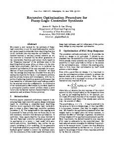
sequential non-leaf nodes , concatenation of events (left then right) || OR (either event below) && AND (events occur simultaneously) * Kleene closure (0 or more) + 1 or more action designates an output activation combinational (terminal) nodes function boolean function (of inputs only) Definition: Acceptance: A sub-machine (specified by a RE-DAG) will accept iff the sequence of inputs matches the entire sequence specified in the DAG. Definition: Action: In the DAG, each unique action corresponds to a unique output of the controller. The output is set high only if the sub-DAG below the action accepts. All sequential behavior exists in the non-leaf nodes of the tree. Each terminal contains an optional Boolean function. Note that there is implicit context passed between nodes in the graph, so acceptance at one location can depend on other parts of the graph. For example, consider the specification in Figure 1. Since it is at the top of the DAG, action “a0” is activated (set high) only when the entire machine accepts (when either of sub-DAGs p2 and p3 accept). The concatenation operators denote the left sub-DAG and right sub-DAG accepting in sequence, while each sub-DAG may require 0 or more clock cycles, itself, to accept. The DAG at p4 recognizes any state. So, action “a1” is activated when z0 and z1 are both high for one clock cycle following any state. Without p4, the action “a1” would activate only if it occurred in the very first clock cycle (the start state). Let T be the number of paths to terminals in the DAG. It is always possible to synthesize a circuit with T+1 memory elements. Note that the DAG in Figure 1 has 9 paths to terminals, thus at most 10 flip-flops in the final machine and up to 2^10 deterministic states. We would like to alter the DAG to decrease the number of terminal paths (and hence memory elements) without altering behavior (this can only be done if the controller actually has less than 2^10 states).
3.0. Regular Expression Minimization Optimal regular expression reduction is known to be NP-Complete, even for RE’s which contain either no OR
operator, or no closure operator [4]. Equivalence testing between two RE’s is equally difficult. Thus, the changes to the RE graph should be incremental so that we can verify the equivalence at each step in the transformation--equivalence must be verified by construction. Six basic DAG manipulation rules are listed below. They can be divided into two categories of rules, and in every rule, the “||” operator, can be replaced by any Boolean connective operator which does not include the NOR function (x0x1 minterm). (In general, the restriction is complex, but intuitively this restriction of the NOR function results from the fact that we are looking for neither sub-graph to be recognized. A machine which recognizes when another machine is “not recognizing” can have quite different behavior, and thus may not have the same behavior after distributing the function across a concatenation operator.) ( A,B ) || ( A,C )-> (A) , (B || C) ( A,C ) || ( B,C ) -> (A || B) , (C) A || A -> A A, (A)* -> (A)+ (A*)* ->( A)* A, (A {action}) -> (A, A) {action}
(Rule 1) (Rule 2) (Rule 3) (Rule 4) (Rule 5) (Rule 6)
FIGURE 2. Rewrite rules used to manipulate the Regular Expression DAG. Parentheses denote a sub-DAG The first set of rules (1-3) directly reduce the number of terminals in the DAG. Consider Figure 1 once again. The sub-DAG “TRUE*” occurs at the beginning of both subDAGs p2 and p3, and represents the same state, since there is no way to determine which “TRUE*” state the machine is in until the machine moves to the next state. We can make use of rule 1 by setting A to be “TRUE*”, B to be all of p2 after A, and C to be all of p3 after A. This
a0 p1 || , p2 , * p4 TRUE
t0
, p3 ,
, a1
+
z0z1 t1
z0 t2
,
z0 t3 *
a2 z0z2 t5
TRUE
t4 FIGURE 1. Example specification DAG. “a0”, “a1”, and “a2” represent the three actions. BDD’s are shown as ovals with the function written inside.
removes a path from the tree. The final reduced DAG is shown in Figure 2. Rules 1 and 2 effectively move the concatenation operators up, closer to the root of the DAG, and the Boolean operators down, closer to the terminals. When a node in the DAG becomes an arbitrary combinational logic function of two terminals, it can always be reduced to a single terminal BDD node. For example, in Rule 1, if DAGs B and C represent combinational functions of the inputs, the sub-DAG (A, B) || (A, C) can be reduced from four paths to terminals to two paths, by creating a BDD node D = (B + C). The second set of rules (4-6) are members of a general class of rules which alter the DAG in ways which improve its canonicality. By making sure that only one type of each equivalent structure shown in rules 4 through 6 exist in the DAG, it is easier to identify larger equivalent sub-DAGs in the DAG as a whole. An example is shown in Figure 3 where rules 5 and 6 together allow rule 3 to remove terminals paths from the graph. Using rule 6 it is possible for actions to be manipulated similarly to operators. The allocation of a separate node in the DAG specification for each action excitation is unique to this paper. Placing these nodes in the graph allows actions to be manipulated for a more canonical graph, and joined with similar actions for optimization. The importance of considering actions during tree manipulations is made clear by the following. Each subDAG provides context to the following sub-DAG, so equivalent sub-graphs with non-equivalent actions cannot be combined into a single sub-graph via rule 2 unless the input context is also equivalent. For example, ( A, C ) ( B, C ) = ( A B ), C
but
( A, ( C { action0 } ) ) ( B, ( C { action1 } ) ) =/ ( A B ), C { action0action1 }
except under two special conditions: 1. A and B are always recognized together, or are otherwise equivalent, or 2. “action0” and “action1” are equivalent. The left side fires “action0” after recognizing the sequence “A,C”, while the right side fires “action0” after recognizing either the sequence “A,C” or “B,C”. On the other hand, for reductions which use rule 1, the action nodes can be ignored since the context is identical
||
action0
action0
, action0
A *
,
=
, * B
A
* B
FIGURE 3. Example: Improving the canonicality of the graph can lead to reduction of paths to terminals.
a0 , ,
, ||
* a1
TRUE
+ a2
t0 z0z1 , t1 z0z2 t2
z0 t4
z0 t3
FIGURE 4. Reduced DAG for the example in Figure 1. Each ti denotes combinational logic with the function inside the oval. for actions in this case
( A { action0 }, B ) ( A { action1 }, C ) = A { action0action1 }, ( B C )
3.1. Algorithm Overview During the minimization, a “unique table” similar to one found in BDD packages[9], is maintained for each node, so that identical nodes are reused, instead of being duplicated. When the algebraic manipulation rules and the unique table are used to reconstruct the DAG from the bottom up, uniqueness of a node is assured by comparing its operator type and left and right pointers. The fact that two identical nodes will never be constructed is ensured, but it is nonetheless possible for two functionally equivalent sub-DAGs to exist. The above rewrite rules and unique table are heuristics which improve the clarity and simplicity of the specification, but do not provide a canonical form. The regular expression reduction occurs as follows: A depth first traversal of the DAG is done, reducing equivalent structures using a set of rules that include rules 4-6,. Where applicable, graph-matching is done, to attempt reductions shown in rules 1, 2. The final DAG is constructed on the way back up. Each final node is placed in the unique table to avoid duplication whenever possible. The reduced DAG for the example in Figure 1 is shown in Figure 1. Note that implementation of the rewrite rules have reduced the number of terminal paths from nine to six. This implies that construction is guaranteed to be done with seven flip-flops or less.
4.0. Efficient Gate Construction After reducing the number of terminals in the tree, the a circuit is synthesized by traversing the resultant DAG. Details of the circuit generation, using construction templates for the various types of operators are given in [11]. Essentially, the construction requires one control point (i.e. one register) for each path to a terminal node. The cir-
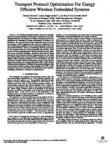
cuit is generated recursively, by allocating registers at the terminals and constructing logic functions of the register outputs (present state bits) according to the type of sequential operator at each node. Logic functions are stored as BDD’s during construction. An example of the synthesis algorithm is shown in Figure 5. Call the set of input variables {Z}, and the set of present state variables {X}. The context for a machine is initially set to the start state. In the figure, f(X,Z) represents the context sent to the DAG. This context is passed to the two children of node P: PL and PR. At node PL, a memory element is allocated, along with optional combinational logic of the input variables. Similarly, memory elements are added for the two terminals of the concatenation operator at PR, t1 and t2. Finally, since P is a OR operator, the acceptance functions from the two children, PL and PR are logically ORed together, and the result acceptance function for the graph, h(X,Z) is returned (and may be passed as context to future machines. The actions of the machine are also created during the machine traversal. Initially, all action functions are set to a Boolean “FALSE” indicating that they will never occur. Whenever an action is encountered in the construction process, its corresponding output function is logically ORed with the current context. This algorithm makes heavy use of memory elements. Typically during construction it is possible to modify existing control points, rather than adding a new one and still represent the state correctly. This reduction cannot be done by the previous algorithm for DAG reduction in Section 3.0.
4.1. Register Removal During Construction Directly allocating control points for each terminal in the graph rarely makes state encodings with the minimum number of registers (as opposed to standard encoding techniques, such as JEDI and NOVA). It is possible to identify two reasons for this: 1. Controllers are constructed so that a state exists for every place an action could occur. This construction is obviously sufficient for any specification, but is hardly necessary for most. Since actions are not attached to every node in the graph, this construction process leads to sets of states which are output-redundant, or indistinguishable to the outside world. 2. Without some form of state space exploration during the construction process, there is no knowledge of how many unique states exist, so the number of control points cannot be reduced based on this information. In order to reduce the number of control points required to build a given machine (with no loss in terms of machine quality or speed of the construction algorithm), it is necessary to gain information about the states of the machine without implementing a DFA model. This can be done by inferring information about the set of reachable states and output-redundant states from the specification graph. Because the information gathered is based on the NFA model of the machine, we preserve the independence of the construction from the potentially explosive STG. Consider the circuit shown in Figure 5 built by allocating one control point for each terminal in the graph. Let us assume t0, t1, and t2 are unrelated functions. The circuit is
A. RE sub-DAG
B. Circuit created without reg. reduction
f(X,Z) h(X,Z) t0(z)
|| PL t1(z)
h(X)
P f(X,Z) t0(Z) ,
PR t1(Z)
t2(Z)
t2(z)
FIGURE 5. A. A sub-DAG, with context f(X,Z) passed to it from the previous sub-DAG. B. The corresponding circuit. built with three flip-flops, which could describe eight possible states. Assuming that the incoming context, f(X,Z), is completely unknown, there are indeed eight states that can exist: any number from zero through three of the terminals can be simultaneously accepting. Above node P, however, there are only four distinguishable states: State 1: no terminals in P accepting, State 2: either t0 or t2 accepting, State 3: only t1 accepting, and State 4: t1 and either t0 or t2 accepting. The state where t0 but not t2, and t2 but not t0 accepting are indistinguishable, or output-redundant to any node above node P. In this example, we can combine control points from t0 and t2 into a single bit, t3. The resultant design has four states encoded by two control points, the minimum possible without examining the effect of the input context, f(X,Z), on the set of reachable states. The function which indicates acceptance of the sub-DAG (labeled h(X,Z) in Figure 5) is used as context for following sub-DAGs. h(X,Z), is used to define conditions for actions to occur and control points to change state. A simpler acceptance function not only reduces the current machine size, but also creates simpler action functions and transition functions for nodes that immediately follow it. The circuit is considerably simpler if construction of t3 allows removal of t0 and/or t2. The circumstances under which this can be done are discussed below. Let ∆ represent the set of transition functions, { δ 0, δ 1, …, δ n } . The set of primary inputs, Z, is { z 0, z 1, …, z k } . The present state of the machine is represented by X, which is actually a set of n Boolean variables, { x 0, x 1, …, x n } , and the next state is represented by Y ≡ { y o, y 1, …, y n } . The mapping from present state to next state is written: ∆:X × Z → Y
Let Λ ≡ { λ 0, λ 1, …, λ m } be the set of action functions, and A ≡ { a 0, a 1, …, a m } represent the actions themselves, then given x i, y j, a i ∈ { 0, 1 } , the mapping from present state to actions is: Λ:X → A Moore machine Λ:X × Z → A Mealy machine Simplification of the acceptance function of a sub-DAG can be performed by creating a new control point x a as
follows. Given a function h ( X′ ) , where X′ ⊆ X , we create a new transition function δ a and corresponding control point xa, such that δ a = h′ ( X , Z ) , where h′ is the function h with every x i ∈ X′ replaced with δ i ( X , Z ) . That is, each present state variable is replaced by its next state function. x a is passed up from the nodes below, as the acceptance function, h(X). h ( x i, x i + 1, …, x i + j ) ⇒ xwhere a , δ a = h ( δ i, δ i + 1, …, δ i + j ) (EQ 1)
The creation of additional control points serves two purposes: 1. It reduces the complexity of the context function h(X,Z) used in subsequent construction. 2. By adding a control point, one or more other control points may become redundant, and can be removed. The determination of the necessary conditions under which it is possible to remove a transition function can be difficult, depending on the scope of modifications to outputs and other transition functions. For example, in the least restrictive case, where arbitrary changes to the controller are allowed, determining whether a control point can be removed is at least as hard as determining whether the FSM currently uses the minimal number of control points to encode state, and therefore requires at least an implicit traversal of the deterministic state space. At this point in the construction, any kind of state assignment or re-encoding technique could be used to reduce the number of control points, but arbitrary reencoding requires at least a partial traversal of the machine’s deterministic state space, which may be very expensive. Alternatively, in the most restrictive case, where no changes to the FSM are allowed, the test for removal becomes simpler: The support of a function F, denoted “sup(F)”, is defined as the set of variables on which F explicitly depends. For each x i ∈ X′ a sufficient condition for removal of transition function δ i is:. x i ∉ sup ( ∆ ) ∪ sup ( Λ )
(EQ 2)
Because of the method of construction, it is quite likely that the sufficient condition expressed in Equation 2 will occur, particularly in the common case where actions are located some distance above the terminals. The reduction and removal process described by Equation 1 and Equation 2 is valid for any acceptance function returned from a node during the build algorithm. In practice, of the standard construction operators already discussed, AND, OR, and closure offer the best chances of control point removal. Implementation with the OR and AND operators are fairly straight forward. The closure operator essentially constructs an or of the incoming context from previous sub-DAGs, and the acceptance function returned by the sub-DAG below it. The circuit constructed using this algorithm for the specification in Figure 1 is shown in Figure 6. Since the final flip-flop has no fanout, it is removed at the end of the build algorithm. If this graph represented only a sub-DAG of the machine, the far right flip-flop would provide the acceptance function passed to following sub-DAGs as context.
z0 z1
action1
action0 z0
z0 z2
accept action2
z0
FIGURE 6. The reduced circuit for the example in Figure 1. A comparison of this controller and one synthesized without DAG reduction, or register removal is shown at the top of Table 2. The number of literals is cut nearly in half, and the number of registers drops from 8 to 3.
5.0. Experimental Data Results for these algorithms are compared against previous results for PBS (using Clairvoyant)[10] and against results based on the extracted, state-minimized STG encoded with NOVA, JEDI, and a simple one-hot scheme. The last three encodings done from a minimized STG are meant to simulate the standard DFA-based synthesis algorithm. All of the examples listed in Table 2 were synthesized with the current algorithms and reduced (via SIS’s “script.rugged”) in less than 40 seconds of CPU time. Using standard encoding techniques, for example JEDI[5] or NOVA[6], some examples could not be encoded and reduced in 40 minutes of CPU time. For each encoding, the three columns below show the number of literals in factored form (L), the mapped logic depth (D) and the number of registers in the design (R). In all examples, SIS’s “script.rugged” was used to simplify the logic. The library used for mapping contained only a latch, a two-input nand, a two-input nor, and an inverter. On the left side of the table are results for implementation making use of the algorithms presented in this paper. The column labeled “states” contains the number of states that exist in these machines. This was determined by reading the BLIF output for the controller into SIS [8] and extracting the STG. Comparison to the PBS compiler results show the compiled designs are uniformly better in at least one of the three categories. On average, the current techniques used 59% fewer registers, 45% fewer literals, and had 8% smaller logic depth. On the right side of the table, the same statistics are shown for NOVA, JEDI, and one-hot encoding. The extracted STG was minimized using STAMINA[7], and the number of states in the resulting STG is shown in the column “min states.” The three encodings were done based on this minimized STG, reduced using “script.rugged” and the results are shown in the table. In the cases where SIS was not able to complete the “script.rugged” in less than 30 minutes CPU time on a SPARC 10 with 32 megabytes of memory, the results are italicized. For each design, the best results are labeled in bold. Note even though JEDI and NOVA used the mini-
design example
L
Current D R
states
Clairvoyant L D R
min states
ex1 (Fig. 1) 13 5 3 8 22 5 8 6 mouse 10 3 2 4 18 5 4 3 xymouse 20 3 4 10 36 5 8 9 mouse2 24 2 6 8 36 5 10 7 xymouse2 48 2 12 50 72 5 20 49 count0 8 5 3 5 16 5 4 4 qr42 46 5 10 33 77 6 21 16 i8251ar 67 8 13 15 85 16 14 15 i2c 115 8 24 70 156 10 37 51 midi 223 16 106 107 604 22 166 104 match1 10 3 3 5 12 4 5 3 match2 21 3 7 15 26 4 12 11 match4 43 4 16 111 56 4 28 79 match8 87 4 36 6151 116 6 63 match16 175 5 80 >107 236 6 138 match32 351 5 176 >1014 476 6 297 TABLE 2. Results for various encoding techniques mum number of registers, only in the very small examples did the encoders offer comparable results in terms of the number of literals and mapped logic depth. Designs “matchn” are machines that recognize when the pattern of the first n input bits match the most recent n inputs. Results for this machine demonstrate the applicability of this algorithm to controllers which could not be constructed with standard encoding techniques. The designs “match8,” “match16,” and “match32” could not state minimized or encoded by JEDI, NOVA, or one-hot because of memory faults that occurred due to the size of the STG.
6.0. Conclusions and Further Work We have described an algorithm for compilation of controllers using extended tree-based regular expressions into a gate-level circuit description. The nature of the specification language makes it highly applicable to protocol intensive machines. Rather than the standard practice of using state space traversal to minimize the machine encoding, observability based on the structure of the tree (an NFA model) has been used to remove unobservable states from the system. Machine construction using these algorithms has been shown to construct fast sequential machines with low literal count. In fact, its efficiency has made it practical in some cases where other encoding methods fail completely.
7.0. References: [1]
R. W. Floyd, and J. D. Ullman, “The Compilation of Regular Expressions into Integrated Circuits,” Jo. ACM. 29:3, 1982.
[2]
L 23 10 42 36 145 8 64 84 323 447 7 38 333
NOVA D R 11 3 11 14 15 4 17 10 36 56 4 10 58
3 2 4 3 6 2 4 4 6 7 2 4 7
L
JEDI D
22 9 10 3 35 6 28 12 440 11 11 6 82 24 84 10 273 46 420 72 8 3 43 12 370 73 unable unable unable
R
L
3 2 4 3 6 2 4 4 6 7 2 4 7
38 10 59 41 618 12 121 81 427 262 9 61 468
one hot D R 9 3 4 8 18 6 12 10 18 14 5 12 18
6 3 9 7 49 4 16 15 51 104 2 11 79
A. R. Karlin, H. W. Trickey, and J. D. Ullman, “Experience with a Regular Expression Compiler,” ICCD, pp 656-665, 1983. [3] G. Berry, G. Gonthier, “The ESTEREL synchronous programming language: design, semantics, implementation,” Science of Computer Programming, vol.19, (no.2):87-152, 1992 [4] M. R. Garey, D. S. Johnson. Computers and Intractability A Guide to the Theory of NP-Completeness, New York: Freeman, 1979. [5] B. Lin, Synthesis of VLSI Designs with Symbolic Techniques, Ph. D. Thesis, Univ. of Calif., Berkeley, UCB/ERL M91/105, Nov. 1991. [6] T. Villa, A. L. Sangiovanni-Vincentelli, “NOVA: State Assignment of Finite State Machines for Optimal TwoLevel Logic Implementations,” IEEE Trans. on CAD, pp 905-924, 1990. [7] G. Hachtel, J. K. Rho, F. Somenzi, and R. Jacoby. “Exact and Heuristic Algorithms for the Minimization of Incompletely Specified State Machines,”EDAC, pp184-91, 1991. [8] E. M. Sentovich, K. J. Singh, L. Lavagno, C. Moon, R. Murgai, A. Saldanha, H. Savoj, P. R. Stephan, R. K. Brayton, and A. Sangiovanii-Vincentelli, “SIS: A System for Sequential Circuit Synthesis,” Electronics Research Laboratory Memorandum No. UCB/ERL M92/41, May 1992. [9] K. S. Brace, R. L. Rudell, and R. E. Bryant, “Efficient Implementation of a BDD Package,” 27th DAC, pp 40-45, June 1990. [10] A. Seawright, F. Brewer, “Clairvoyant: A Synthesis System for Production-Based Specification,” IEEE Trans. on VLSI, pp 172-185, June 1994. [11] A. Seawright, Grammar-Based Specifications and Synthesis for Synchronous Digital Hardware Design, Ph. D. Thesis, Univ. of California, Santa Barbara, June 1994.