Controlling 6R Robot by Visionary System Azamossadat Nourbakhsh1, Moharram Habibnezhad Korayem2 1
2
Artificial Intelligence and Robotic Department, Islamic Azad University, lahijan Branch Lahijan, Iran
[email protected]
Robotic Research laboratory, Mechanical Engineering Department, Iran University of Science and Technology Tehran, Iran
[email protected]
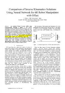
Abstract— In the visual servoing systems, the data obtained by Visionary is used for controlling robots. In this project, at first the simulator which was proposed for simulating the performance of a 6R robot before, was examined in terms of software and test, and in the proposed simulator, existing defects were obviated. In the first version of simulation, the robot was directed toward the target object only in a Position-based method using two cameras in the environment. In the new version of the software, three cameras were used simultaneously. The camera which is installed as eye-inhand on the end-effector of the robot is used for visual servoing in a Feature-based method. The target object is recognized according to its characteristics and the robot is directed toward the object in compliance with an algorithm similar to the function of human’s eyes. Then, the function and accuracy of the operation of the robot are examined through Position-based visual servoing method using two cameras installed as eye-to-hand in the environment. Finally, the obtained results are tested under ANSI-RIA R15.05-2 standard.
Keywords—6R Robot , camera, visual servoing, Feature-based visual servoing, Position-based visual servoing, Performance tests. I. INTRODUCTION In this document, use of visual characteristics and parameters in controlling and directing the end-effector of the robot is discussed. The aim of visual servoing is to control the robot using the data created by vision. The working field of this project includes Machine Visionary Systems and industrial robots. The relation between these two technologies is highly regarded as important, since it gives us new possibilities in production of systems by adding visual possibility to them. Because robots are expensive and highly sensitive, using software simulation of the robot helps in becoming familiar with functions of a real robot and it is possible to realize points of strength and weakness, also the movement limitations of the robot, and after getting fully acquainted with the function of the robot, it can be moved to the real robot. Actually this is why the simulation of 6R robot is performed.
Nowadays, in order to make the functions of a robot similar to those of a mankind, there is a need for facilities like human’s eyes providing a comprehension of their surroundings. This is why different cameras are used to control the robot. Through these cameras, like human’s eyes, a picture of the environment is taken and sent to the brain of the machine in order to be processed, and after the process is done, the robot decides on the necessary measures. In this project, the operation of recognizing the object by camera is programmed exactly similar to recognition done by human’s eyes. Visionary systems are often classified in terms of the number of cameras and their position. Visionary systems which use just one camera are used more often than those which employ more than one camera, due to their economy and ease of production. On the other hand, using camera as a stereo structure (such as observing the environment using two cameras) eases many of visual problems of computers. Gregory Flandin has explained the manner of using cameras in eye-in-hand/eye-to-hand ways in controlling robots [4]. These two which have different functions in industry, are completely differentiated. In eye-in-hand method, the camera is set on the end-effector, while in eye-to-hand method the camera observes the entire environment of the robot and is installed outside the robot. The other important issue in a robot is recognition of the target object and visionary systems were used in order to improve the accuracy of robots and had a notable use in this field. N.J. Ferrier discusses on this issue in an article [5]. There is also a review on visual servoing done by Hutchinson [6]. He has explained the principles of visual servoing based on geometric characteristics. Croke showed that efficiency of visual servoing algorithms can be improved by employing a model of System Dynamics [2]. Skaar and his colleagues suggested that many of requirements of the real world can be covered using the performance of scope space of one or more cameras [7]. Viewpoint and characteristics of a robot with a camera on its end-effector are functions of points depending on the camera in accordance with the target object. Usually this function is non-linear and coupled horizontally, in a way that the degree of movement freedom of the end-effector is resulted from complex movement of many characteristics. For the sake of simplicity and easiness, these relations can be made linear for the predetermined point.
The Feature-based method is used in many researches for visual servoing. In these researches, a closed circle is used for controlling the joints of the robot. Feddama has used the concept of a Characteristic Space Way Generator and controlling the close-circled joint to overcome the problem of low range of visual sampling. Laboratory projects of Featurebased visual servoing are fixed for 4-degree free robots [5]. Hashimoto et al. have proposed a simulator for comparing Feature-based and Position-based methods [9]. Also controlling through vision and test of a 3P labeler robot is designed and simulated by Korayem et al. [2]. In this project, the error of locating the end-effector was reduced to a very low amount and also error was analyzed under ANSI-RIA 15.05-2 and ISO 9283 standards, and the proposed method reduced the amount of error. In this method, a camera which is set on the end-effector of the robot is used for finding the target and the end-effector is controlled to reach the target using a Featurebased visual servoing method. Two cameras which are placed in the environment and a Position-based visual servoing method have been also used in order to test the robot. In this simulator, just one camera is used for the control operation. In visionary operation, the controlling algorithms calculate the quantities of distance between the end-effector and the target object as Delta X and Delta Y and then the end-effector is directed to the next location. After relocating, another picture is taken from the working environment of the robot and the operation repeats. This operation repeats until the time when the errors of X and Y axes become zero and the object will be located in the center of the plan of the camera which is installed on the end-effector of the robot. Then, the length of the arm is set by minimizing Delta Z (by minimizing the error in Z axis taking into consideration the amount of difference in size of the object). This means that the favorite size of the object is observed in the picture, calculated and used as a characteristic for recognition. In the robotic laboratory of the University of Science and Industry, a robot is produced with a 6 degree of freedom and joints that move in a rotational manner. There is also software proposed for simulating the function of a 6R robot in Position-based visual servoing [3]. In this software, two cameras are used which are placed in the environment in a specific distance. The pictures taken by the cameras are seen in the picture plan as two dimensional specifications. In order to convert the points to 3D points in Reference Coordinate System, a three-layered back propagation nervous system is used. Then, considering the recognition of the end-effector and the object (taking into account their color), in three dimensional coordinate, it is tried to reduce their location difference to zero. The exactness of performance in this simulating system is examined under ISO 9283 and ANSI-RIA R15.05-2 standards. In this simulator, which is the second version of the simulating software of 6R robot, first, the problems of the previous system are obviated and then measures are taken in order to create a Feature-based vision for controlling the robot. In this simulator, three cameras are used simultaneously. The operation of controlling the robot is done through Featurebased visual servoing, and with respect to the characteristics of
the target object and their recognition by the robot, accessibility to the targets becomes plausible. In this condition, there is one camera which is installed on the end-effector of the robot, and the pictures taken by this camera are analyzed. After recognizing the target object, the robot moves toward it. The considered characteristics in this project are color and the object. Two cameras, number 1 and number 2, take pictures of different stages and the pictures are saved. Also, Feature-based method is used in order to test the performance of the robot. In this case, two cameras which are installed in the environment are used (cameras number 1 and 3 which are installed on the ground in a certain distance and observe the robot from its front and from the right angle). After analysis of the picture and recognition of the target object and the end-effector, their locations in the coordinate of the picture are estimated, and then the visionary system moves the end-effector toward the target object. Since there is a need for the mapping of the picture plan coordinate for the reference coordinate in order to have the locations of the end-effector and the object in the Global Reference Coordinate, nervous system is used instead of mapping. By this nervous system, the two dimensional data of location of objects acquired by the pictures of the two cameras, are converted to three dimensional data of location which is recognizable by the robot. Then the robot tries to reduce the location difference of the target object and the end-effector to zero. In order to solve the kinematics equations of the robot, two methods of Inverse Kinematics and Direct Kinematics are employed. In Direct Kinematics method, quantities of angles of the joints are accessible. Based on Direct Kinematics equations, the three dimensional location of the end-effector is determined. In Inverse Kinematics method, having the quantities of three dimensional location of the end-effector available, and using the matrix of transition and inverse kinematics equation, angles of joints of the robot are calculated. By using the difference of these two quantities, the location error of the robot is determined. Also the movement of the robot in different Paths is tested and the obtained results are tested under ANSI-RIA standard. Some of the amendments in the new version of the software are as follow: In the previous version, float variables were used and through converting them to double, some data would be lost. The proposed formulas for the robot were conducted for the cases where Z axis is facing upward, in other words, where the machine in left-handed. But DX uses a righthanded axis, thus Y axis faces upward, and this issue had caused obvious errors in calculations. In the previous version, due to the use of CImg library and because the pictures which were taken from the RGBA window were 32 bit ones, the converting program of this library ran as a process in the memory and since the resources taken by this program were not released, a huge space was overtaken. Since browsing needed lots of
pictures being taken, instead of this, GDI+ library was used. Obviating the existing problems on the Paths of the robots. In the “Get Target” function, instead of calculating the specifications by Net1 (the designed nervous system), they were taken directly from the three dimensional space, and certainly in case the inverse kinematics was correct, the movement of the robot was correct too, and the accuracy of performance of Net1 couldn’t been examined.
Also these were among the possibilities added to the software: Adding new windows and dialogues for ease of making contact to the program by user Making the installing program for the project Combining two PB and FB projects in one project with three cameras in one environment Possibility of observing the real location of end-effector in space and the angles in each moment Possibility of seeking the object in terms of its shape and color and saving the pictures of each and every step Adding Jacobean calculations in order to achieve singular points of the robot Beautifying and making the output messages which are given while all of the movements in Direct and Inverse Kinematics, which free the operation of the program from necessity of accessibility to the data files II.
INTRODUCING THE 6R ROBOT
This simulator is made for the robot which is designed in the University of Science and Industry .This Robot has 6 degrees of freedom and all of its joints are of revolute kind. As seen in Figure. 1., it has 3 degrees of freedom in its body, shoulder and head and also 3 degrees of freedom in the end-effector which perform the roll, pitch and yaw rotations. The first arm rotates horizontally around the vertical axis. The second arm rotates in an axis which is vertical comparing to the axis around which the first arm rotates, and the third junction rotates in a parallel line comparing to the second junction.
III.
INTRODUCING THE SIMULATOR SOFTWARE
In this part, the simulator software is introduced: A. Getting familiar with the software One of the aims of this project is to employ a set of issues related to the vision on machines, from the way of taking pictures by camera to processing the picture and recognizing the predetermined object and finally controlling the robot by vision, and this is why a 3D environment for the project of simulation of a 6R robot has been created. In this software, 3 cameras have been used. The user can do the monitoring job by switching to any of these cameras at any moment. By the camera which is installed on the end-effector (the main camera used for controlling), the simulation software receives the data exactly similar to the real situation and after processing the pictorial data, numbers the observed objects and seeks an object with the characteristics of the target object. If the object was not seen in the first picture taken, the visionary system moves the end-effector of the robot in the working space and takes another picture. This function repeats so long that either the visionary system observes the predetermined object or it browses the entire working space and doesn’t find the target. After recognition of the target by the visionary system, the robot starts moving by a controlling algorithm which is applied by the visionary system, and the camera installed on the endeffector of the robot takes picture of the working environment continually and the operation repeats until the end-effector gets placed in a certain distance from the target.
Fig. 2 A scene from the new software used for visual servoing
Fig. 1 structure of a 6R Robot
According to the definition, robotic operations include moving pieces or tools in space using a kind of mechanism. Optimum use of the function of the arm depends on accurate controlling of the movements and controlling the movements accurately is possible by recognizing and defining them by appropriate mathematical quantities.
The aim of installing two cameras in the environment is observance of the entire space in which the robot is placed by the observer. These cameras are not fixed and can be moved by the user in any point of the space. The camera number 1 looks at the robot from the right side and the camera number 3 observes the robot from its front side. In this software, it is possible for the object to move in accordance with the different planes of coordinate axes. In this condition, the location of the selected object in the picture plan can be changed using the left button of the mouse. Also each of the selected objects rotates around X, Y or Z axes. This function is performed by the right button of mouse.
B. Recognition of the working space of 6R Robot Since the location and direction of the end-effector is directly related with the displacements of the joint, in order to make the movements of the joints proportional, the differential relations between displacements of the joint and the location of the end-effector is worked out and then they are solved for the movement of each separate joint. The matrix which includes derivatives of the position of the end-effector in accordance with the displacements of the endeffectors is called the Jacobean of the mechanical arm. The points where the determinant of the Jacobean matrix equals zero, are called Singular Points and the movement of the robot is performed in a vertical direction. Since the movement of each of the joints has a limited scope and junction of the joints limits their movement scope, the need for knowledge of the working space of a robot seems necessary [1].These issues make some problems in the matter of movement of the robot and deprives us of reaching favorite results in simulation. For this reason, calculation of Singular Points and the working space of the robot seems essential. Based on this, the working space of the robot is determined by Matlab Simulink. Considering the obtained 3D figure, the domain of the true quantities is distinguished.
direction is toward the positive area. If the object is not recognized in a single movement Path, arm of the robot extends as much as one step and this operation repeats until the time when the robot finds the object. First, one picture is received from the camera installed on the end-effector of the robot. After processing the picture and recognition of the object by the visionary system, the end-effector of the robot is directed toward the object. In this step, the applied algorithm works exactly similar to human’s eyes and checks the border points of the picture. After some steps, the center of the object will be coincided with the center of the picture. In this condition, it’s time to adjust the distance between the endeffector and the object. In this condition, the visionary system moves in maximum 15 steps to catch the object. Pictures of the different stages of this process are taken by cameras number 1 and 2, and saved in two folders named Cam1 and Cam2.
B. Testing the Robot via Vision In this stage, using a Position-based method, our efforts to execute the movement of the robot for catching the object have been put. First, locations of the target object and the endeffector are distinguished by cameras number 1 and 3 which are placed in the environment. Then, using the nervous system and by solving Inverse Kinematics equations, the difference between the locations of the end-effector and the target object is reduced to zero. The nervous system is used to convert the two dimensional specifications received from the plans of the picture to three dimensional specifications in the space.
V. PERFORMANCE TESTS
Fig. 3 Representation of working space of a 6R robot (a hollow hemisphere)
The performance tests on the robot are performed in three states of Direct Kinematics, Inverse Kinematics and movement in defined Paths. A. Direct Kinematics
IV.
VISIONARY OPERATION OF THE ROBOT
In controlling the robot via vision, two principal operations is considered: first is the ability of the robot in performing the desired operation, and then bringing the test operation into action. A. Controlling the Robot via Vision In this software, using a Feature-based method, the robot is controlled to reach the target object. The distinguishing process is done based on two characteristics of color and shape. As seen in Figure2., there are different objects in the working space of a robot. In the working mechanism of visionary system, two conditions are considered: up to down, and vice versa. In a situation when the object is located in a farther distance, using up to down method brings about the result sooner. In the case of down to up, the robot starts searching from the lowest point of its working environment. Regarding the amount of the step, the amount of displacement in every movement is distinguished. At first, the movement
In this system, first, the general conversion form that relates frameworks which are connected to continuous connector to each other, are obtained. By combining singular general conversions, the location and direction of the connector of 6 relative is reached to connector of zero. In order to solve the modeling of a 6R robot, the Denavit-Hartenberg symbolization is used. The general conversion of T06 can be calculated by matrix multiplication of conversion matrixes. The T06
matrix
determines the position and direction of the end-effector relative to the reference coordinate and is called Transition Matrix. In Direct Kinematics test, the quantities of joint angles are determined. On the basis of the given angles, the location of the end-effector is calculated by the system and via the Transition Matrix. By the difference between the real location of the endeffector on the screen (Real End-Effector Position) and the theoretical attained location (P Vector), the location error of
B. Inverse Kinematics In case there is a determined optional point and direction of movement, in order to find the quantities of joint angles which hold true in direct equation, solving the Inverse Kinematics of the robot is needed. In Inverse Kinematics test, the specifications of the location of the end-effector are accessible. Using Inverse Kinematics equations, the quantity of joint angles are distinguished and the robot rotates to that quantities and on this basis, the location of the end-effector in space becomes distinct. The difference between the given location and the attained location reveals the location error of the Inverse Kinematics test. This error is shown in the diagram of Figure 4.b. Also Inspection of Errors in Continuous path is shown by Nourbakhsh [11], that the end-effector of the robot is moved on a certain Path. The location of the end-effector in every moment is acquired by two cameras which are fixed in a specific distance from each other. In this method, two cameras observe the end-effector from outside. In this case, three different Paths of line, circle and rectangle are tested in the movement of the robot.
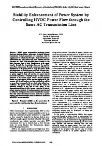
cameras are used which are placed in the environment and through Direct Kinematics test, corresponding points of optional points are obtained and the diagram of these points, shows the accuracy in movement of the robot. Also quantities of test parameters for 6R robot for 20 points with 10 times of repetition are obtained: The maximum accuracy parameter is estimated as AC 0.633451. Average of Path accuracy is also estimated as AC 0.267432 . Quantities of u and v are also calculated aj aj
and their histograms are seen in Figures 8 and 9. 4 3.5 3 2.5 (mm)
the machine is determined. Figure4.a shows the diagram of the location error of the system in Direct Kinematics.
2 1.5 1 0.5 0 1
2
3
4
5
6
7
8
9 10 11 12 13 14 15 16 17 18 19 20 )j(نقاط
Fig. 5 Diagram of centers of gravity of lengths of ( u a ) points j
Quantities of Dij of Path deviation are also estimated and their histogram is observed in Figure10. 3.5 3
Inverse Kinematic Errors
Direct Kinematic Errors
2.5
0.5
mm
0.2
0.6
0.1
0.4
2 1.5
0.3
0
0.2
1
-0.1
0.1 0
ex
-0.1
ey
-0.2
ez
-0.2
ex ey
-0.3
-0.3 1
-0.4 -0.5
ez 2 3
ez 2
3
4
0 1
4
2
3
4
5
6
7
8
9
5
5
6
7
ex 8
9
10
10 11 12 13 14 15 16 17 18 19 20 )i(نقاط
6 7 8
ez 9
ey 10
ex
Fig. 4 (a): the location error diagram in Direct Kinematics (b): the location error diagram in Inverse Kinematics
C. Measuring Examination of the Function of the Robot Based on ANSI-RIA R15.05-2 International Standard of United States of America In order to inspect function of robots, there are several standard methods which evaluate different functions of robots. The aim of this standard is to provide technical information in order to help users in choosing the most appropriate robot for their favorite job [10]. This standard defines significant criterions on the basis of Paths and then proposes some methods for evaluating them. These criterions include: relative accuracy of the Path, absolute accuracy of the Path, capability of repeating the Path, Path rapidity characteristics and angular deviation. Evaluating the mentioned criterions is one of the most appropriate methods of evaluating general competency of industrial robots on the basis of Path. Also estimating these criterions brings about the possibility of comparing competency of similar robots. In applying examinations on performance of the robot, two
Fig. 6 diagram of centers of gravity of widths of ( v a ) points j
By using the attained quantities for Dij, maximum repeatability is estimated as equal to PR 0.0034 and average repeatability equal to PR 0.005943 . Dij(Deviation)
0.12
0.1
0.08
Error(mm)
1
0.5
0.06
0.04
0.02
0 1
2
3
4
5
6
7
8
9
10 11
12
13
14
15
16 17
18
19
Test
Fig. 7 diagram of deviation amount of Dij for the 6R Robot
Also quantities of CR (Cornering Round-off error) and CO (Cornering Overshoot) for a rectangular Path are found as follow: CO=0.240985 mm CR=0.0650 mm
VI.
CONCLUSION
In this piece of text a simulator , which is used for control of a 6R Robot , is introduced . In this visionary system, a combined version of Feature-based and Position-based methods of visual servoing is used and this software has been able to perform visual servoing of a robot with a good deal of proximity to reality, using a 3D graphic environment. Possibility of using 3D facilities in movement and rotation of any object in the environment, contributes a lot to comprehension of 3D environment and becoming familiar with it. To control the robot, Feature-based method was applied . in this part, the characteristics of color and shape of objects were used in the environment. Since the camera installed on the end-effector was used in this method, a controlling algorithm similar to the function of human’s eyes was employed. To take performance tests in accordance with the existing standards, two cameras placed in the environment for processing the data and obtaining the location of the endeffector relative to the reference coordinate is used. In this simulator, ANSI-RIA standard is observed from among different existing standards, and under the fixed norms of ANSI-RIA standard (The international standard of the United States of America) statistical and scientific analysis of the robot is made. REFERENCES [1] Asada and Slotain , Translated by Dr. Moharram Habibnezhad Korayem,” Analyzing and control of Robot” , Published by Iran University of Science and Technology ,May 1997.(In Farsi) [2] Aliakbarpour, Hadi,“ Vision Simulating and introducing an algorithm for Image Processing and using in the Robot” , Thesis for taking M. S., Science and Researches Branch of Islamic Azad University, 1999. [3] Heidari, Fatemeh.S., "Simulation of Visual Servo Control and Performance Tests of the 6R Robot Using Position Based and Image Based Approach", Thesis for taking M. S., Iran University of Science and Technology , October 2006 [4] Geregory Flandin, “Eye-in-hand/Eye-to-hand cooperation for Visual Servoing “, IEEE Press, 2000. [5] J. T. Feddema, C .S. G Lee,O. R. Mitchell, “Weighted Selection of image Features for resolved Rate Visual feedback Control ”,IEEE Transaction on Robotics and Automation, Vol. 7, No 1, pp. 31-47, 1991. [6] Seth Hutchinson,Gregory Hanger, and Peter I. Croke,”A Tutorial on Visual Servo Control”, pp.6-12, May 1996. [7] Peter I. Croke, Malcom C. Good, “Dynamic Effects in Visual Closed Loop Systems”,IEEE Trans. on Robotics and Automation., Automation, pp. 671-683, Oct 1996. [8] S.Skaar,W.Brockman,and R.Hanson.Camera-Space Manipulation. Int.J.Robot.Res.,6(4),pp.20.32,1987. [9] H.Hashimoto,T.Kimoto, T.Ebin, "Manipulator Control with Image Based Visual Servoing ", In Proc. IEEE, Conf. Robotics and Automation , pp.2267-2272,1991. [10] American National Standard for Industrial Robots and Robot Systems Path-Related and Dynamic Performance Characteristics Evaluation. ANSI/RIA R15.05-2. Apr. 16 2002. [11] Nourbakhsh, Azamossadat ,"6R Robots; How to Guide and Test them by Vision?",Conf CSICC2008,Springer pp.870-875