Coordinate Assignment for Cyclic Level Graphs Christian Bachmaier1 , Franz J. Brandenburg1 , Wolfgang Brunner1 , and Raymund Fülöp2 1
2
University of Passau, Germany, {bachmaier|brandenb|brunner}@fim.uni-passau.de Technische Universität München, Germany,
[email protected]
Abstract. The Sugiyama framework is the most commonly used concept for visualizing directed graphs. It draws them in a hierarchical way and operates in four phases: cycle removal, leveling, crossing reduction, and coordinate assignment. However, there are situations where cycles must be displayed as such, e. g., distinguished cycles in the biosciences and scheduling processes which repeat in a daily or weekly turn. This excludes the removal of cycles. In their seminal paper Sugiyama et al. introduced recurrent hierarchies as a concept to draw graphs with cycles. However, this concept has not received much attention in the following years. In this paper we supplement our cyclic Sugiyama framework and investigate the coordinate assignment phase. We provide an algorithm which runs in linear time and constructs drawings which have at most two bends per edge and use quadratic area.
1
Introduction
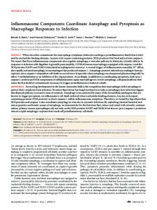
The Sugiyama framework [9] is among the most intensively studied algorithms in graph drawing. It is the standard technique to draw directed graphs, and displays them in a hierarchical manner. It consists of the four phases of cycle removal, leveling, crossing reduction, and coordinate assignment. Typical applications are schedules, UML diagrams, and flow charts. In its first phase the Sugiyama framework destroys all cycles. However, there are many situations where this is unacceptable. There are well-known cycles in the biosciences [7], where it is a common standard to display these cycles as such. Another inevitable use are repeating processes, such as daily, weekly, or monthly schedules which define the Periodic Event Scheduling Problem [8]. In their seminal paper [9], Sugiyama et al. proposed a solution for both the hierarchic and the cyclic style. The latter is called a recurrent hierarchy which is a level graph with additional edges from the last to the first level. It can be drawn in 2D where the levels are rays from a common center (see Fig. 1(a)) and each edge e = (u, v) is a monotone counterclockwise poly-spiral segment from u to v wrapping around the center at most once. An alternative is a 3D drawing on a cylinder (see Fig. 1(c)). A combination would be the best of both worlds: an interactive 2D view with horizontal levels. It can be scrolled upwards and downwards infinitely and always shows a different part of the cylinder, see Fig. 1(b) for a snap shot, which also represents our intermediate drawing.
2
3
5
left
x
1 3
1
2
left
y
6
3
2
4
4 y 4
8
7
x 2
1
1
5
3
6 right
right
4
11
8
7
15
10
5
14 13
6
9
12
10
13
11
15
14
9 12
5
0
6
(a) Cyclic 2D
6
9
13
12
11
10
x
1
right
2
3
3
5
1
1
yz
2
5
6
(c) Cyclic 3D
4
6
8
7
4
x
2
left
y
15
14
20
1
(b) Intermediate 1
5
0
1
10
9
12
13
14
11
15
(d) Hierarchic Fig. 1. Example drawings
In cyclic drawings edges are irreversible and cycles are represented in a direct way. Thus, the cycle removal phase is not needed. This saves much effort, since the underlying feedback arc set problem is N P-hard [4]. Further advantages over hierarchic drawings (see Fig. 1(d)) are shorter edges and fewer crossings. A planar recurrent hierarchy is shown on the cover of the textbook by Kaufmann and Wagner [6]. There it is stated that recurrent hierarchies are “unfortunately [. . . ] still not well studied”. After investigating the leveling phase [1], we consider the coordinate assignment phase for the cyclic case. There are several algorithms for non-cyclic coordinate assignment [6]. We modify the established algorithm of Brandes and Köpf [3] for cyclic level graphs and provide a linear time algorithm using quadratic area and with at most two bends per edge.
2
Preliminaries
A cyclic k-level graph G = (V, E, φ) (k ≥ 2) is a directed graph without self-loops with a given surjective level assignment of the vertices φ : V → {1, 2, . . . , k}. Let Vi ⊂ V be the set of vertices v with φ(v) = i. For two vertices u, v ∈ V let span(u, v) := φ(v) − φ(u) if φ(u) < φ(v) and span(u, v) := φ(v) − φ(u) + k otherwise. For an edge e = (a, b) ∈ E we define span(e) := span(a, b). An edge e with span(e) = 1 is short, otherwise long. A graph is proper if all edges are short. Each cyclic level graph can be made proper by adding span(e) − 1 dummy vertices for each edge e and thus splitting e in span(e) many short edges, which
we call the segments of e. In total, this leads up to O(|E| · k) new vertices. The first and the last segment of each edge are its outer segments, and all other segments between two dummy vertices are its inner segments. A proper cyclic k-level graph G = (V, E, φ,