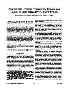
Coordinated Operation in a Multi-Inverter Based. Microgrid for Both Grid-Connected and Islanded. Modes Using Conservative Power Theory. Ali Mortezaei, M.
Coordinated Operation in a Multi-Inverter Based Microgrid for Both Grid-Connected and Islanded Modes Using Conservative Power Theory Ali Mortezaei, M. Godoy Simões
Ahmed Al Durra
Fernando P. Marafão
Tiago D. Curi Busarello
Department of EECS Colorado School of Mines Golden, CO, USA
Department of EE The Petroleum Institute Abu Dhabi, UAE
Control and Automation Eng. UNESP – Univ Estadual Paulista Sorocaba, SP, Brazil
School of ECE University of Campinas Campinas,SP, Brazil
Abstract— In order to address the power quality enhancement in a given microgrid, independent control of reactive, unbalanced and distorted load current components, in a multiinverter-based approach may be required. Therefore, this paper proposes a coordinated control strategy using the Conservative Power Theory (CPT) and assuming the contribution of all grid connected interfaces, especially those related to Distributed Generators (DG). For grid-connected operation, a coordinated current-controlled operation is proposed for supplying different load current components, improving power quality and consequently, minimizing the PCC voltage disturbances. In case of islanding operation, the microgrid may suffer from serious power quality problems due to the presence of nonlinear and/or unbalanced loads. To mitigate such current disturbances, a master-slave-based cooperative operation for DGs is presented. Since each primary source has its own constraints and topology, a supervisory control is considered to determine sharing factors for each current component. The microgrid system is controlled in abc-frame, offering a very flexible, selective and powerful load current sharing scheme, as demonstrated through digital simulations. The principles supporting the proposed control schemes are also discussed. Index Terms—Microgrid, Conservative Power Theory, Cooperative Control, Distributed Generation, Power Quality Improvement, Current Sharing.
I.
INTRODUCTION
Due to the growing progress of renewable energy based distributed generation (DG) and the associated power electronics development, the number of installed distributed generation systems have been increased continuously [1]-[3]. Moreover, for enhanced operation of modern microgrid, the coordinated control of parallel interfacing DG units has been introduced [4]–[7]. It is well accepted that a microgrid can operate in both grid-connected and intentional islanding modes to increase reliability to critical loads. In such systems the DG units mainly focus on the fundamental active and reactive power supplying. However, two important issues that need to be addressed are the power quality and undesirable current sharing, particularly in the low-voltage distribution network,
978-1-4673-7151-3/15/$31.00 ©2015 IEEE
where electronic devices are drawing distorted and unbalanced currents. The interactions of such current disturbances with high feeder/line impedances, in a lowvoltage system, may cause considerable voltage deterioration and possibly affect sensitive loads. Power converters have unequal capabilities in the generation of different components of electrical power. Active and reactive powers are generally shared among converters based on their ratings and availability of primary power sources, while the structure of the converter, as well as the switching frequency are determining issues for harmonic and unbalanced sharing. Converters with higher switching frequencies are capable of providing higher order harmonics [8], [9]. In a microgrid, in order to be able to control all of the current components of the load, among different converters, a new control strategy for these power electronic interfaces should be developed. In the literature, there are two methods for coordinated control of voltage source inverter (VSI)-based microgrids, which can be classified into two types: communication based [10]-[14], which relies on communication for reliable operation and it can be adapted in systems where DGs are connected to a common bus or located in close proximity, and droop based [15]-[18], defined as wireless with no interconnection between the inverters, in which the voltage and frequency of the network are employed instead of applying a communication link, although it does not ensure constant frequency and amplitude of microgrid voltages, as droop methods are load dependent. Therefore the use of a low bandwidth communication system seems inevitable for an additional control level to tune voltage amplitude and frequency. In such context, the objective of this paper is the development of a coordinated operation methodology for independent control of the load current components among converters in a multi-inverter-based microgrid. CPT is used to generate different current references for selective disturbances mitigation and active power injection. The CPT current decompositions results in several current related terms
4602
associated with specific load characteristics [19]. These current terms are orthogonal (decoupled) and could be used by the control system to generate the current reference for each converter depending on the existing load, as well as the specified share factors set by a supervisory control. In the grid-connected mode, where the output voltage and frequency are dictated by the utility grid, a cooperative operation based current-mode control is implemented to supply the load current components, allowing the multifunctional DG inverters to improve power quality in weak grids. Using this strategy, the total load current can be supplied by inverters enabling a smooth switching between grid-connected and islanded modes. In islanded microgrid, all the DG units are responsible for maintaining the system voltage and frequency, while sharing the load power components. Providing undesirable load power components may distort the line voltage, which can propagate throughout the distribution system and can cause the voltage in a microgrid to suffer from magnitude deviation, distortion, and imbalance. Thus, a cooperative operation based master-slave control is developed, in order to maintain the power balance in islanded mode, as well as enhancing the power quality indices at sensitive loads, by means of the participation of all DG units. Simulation results will be demonstrated to validate the benefits of the proposed control approach in both, coordination of different converters and the resulting current sharing and power quality improvement. II.
CONSERVATIVE POWER THEORY – BRIEF REVIEW
The Conservative Power Theory [19] proposes power and current’s decomposition in the stationary frame, according to terms directly related to electrical characteristics, such as: average power transfer, reactive energy, unbalanced loads and nonlinearities. Assuming a generic poly-phase circuit under periodic operation, where (�)ݒ, (�݅�) are, respectively, the voltage and current vectors and (�ݒොሻ is the unbiased integral of the voltage vector measured at a given point of common coupling (phase variables are indicated with subscript�Dzdz), the CPT authors define: Active phase currents are defined by: ݒۃ ǡ ݅ ۄ ݒǤ ݅ ൌ ԡݒ ԡଶ
(1)
Reactive phase currents are given by: ݒۃො ǡ ݅ ۄ ݒො Ǥ ݅ ൌ ԡݒො ԡଶ
(2)
Void phase currents are the remaining current terms: ݅௩ ൌ ݅ െ � ݅ െ ݅ Ǥ
(3)
(5)
The unbalanced active currents are calculated by difference between (1) and (4): ௨ (6) ݅ ൌ ݅ െ ݅ . In the same way, the unbalanced reactive currents are ௨ ൌ ݅ െ ݅ . ݅
(7)
Thus, the total unbalance phase current’s vector is defined as: ௨ ௨ ௨ (8) ൌ ݅ ݅ . ݅ Finally, the total current vector can be split as: ݅ ൌ ݅ ݅ ݅௨ ݅௨ ݅௩ Ǥ III.
(9)
MICROGRID WITH CPT SUPERVISORY CONTROL
Fig. 1 presents the configuration of the multi-inverterbased microgrid system. This system consits of three sets of VSI based DG units connected through line impedances to the network loads. The load center is connected to the distribution network at PCC via a Static Transfer Switch and grid impedance. For the purpose of simplicity, all VSIs are assumed to have the same topology. Each VSI consists of a three-phase �� output filter connected to the network loads via equal line impedances. The inductance and capacitance of the filter are�� �and ��� respectively, and � is the ohmic resistance of the inductor.��୪ and � and � ୪ and � �represent the inductance and resistance of the line and grid impedances, respectively. The effect of the DG unit is represented by a DC voltage source, connected in parallel with the VSI DC-link capacitor. The parameters of the microgrid system and network load are provided in Table I and II, respectively. TABLE I - MICROGRID PARAMETERS
Nominal phase voltage, ݒ௦ Grid frequency, ݂ Maximum power output of inverters Switching frequency, ݂௦ Output filter inductor, ܮ Output filter resistor, ܴ Output filter capacitor of Masters,�ܥ Line & Grid inductor, ܮ & ܮ Line & Grid resistor, ܴ & ܴ DC link voltage, ܸ Carier amplitude, ݒ௧
127 V 60 Hz 4 KVA 30 KHz 4 mH 0.15 ohm 10 uF 1 mH 1 ohm 450 V 5V
TABLE II - LOAD PARAMETERS
The active and reactive phase currents can be further decomposed into balanced and unbalanced terms, which refer to load symmetry, not to current symmetry. Thus, the balanced active currents have been defined as: ݒۃǡ ݅ۄ (4) ൌ ݅ ଶ ݒ ฮݒฮ
The balanced reactive currents have been defined as: ݒۃොǡ ݅ۄ ൌ ො Ǥ ݅ ଶݒ ฮݒොฮ
Load inductor, ܮଵ Load inductor, ܮଶ Load capacitor, ܥଵ Load resistor, ܴଵ Load resistor, ܴଶ Load resistor, ܴଷ Load resistor, ܴସ Load resistor, ܴହ Load resistor, ܴ Load resistor, ܴ
4603
50 mH 4 mH 220 uF 5 ohm 10 ohm 50 ohm 30 ohm 60ohm 40 ohm 300 ohm
il oadabc
vpcc/loadabc Fig. 1. Schematic diagram of a multi-inverter-based microgrid.
IV.
DYNAMIC MODEL OF THE CURRENT-CONTROLLED OR SLAVE VSI-BASED DG
ܩ ሺݏሻ ൌ ܩ௩ ሺݏሻܩ௧ ሺݏሻܯሺݏሻܥ ሺݏሻ
In this section the control strategy for the currentcontrolled VSIs is presented [20]-[22]. The current-control scheme shown in Fig. 2 is based on the
-reference frame for both grid and islanded modes of operation. �୧ ሺሻ is the current controller consisting of a lead compensator in addition to a pole at the origin, as in (Eq.10), which provides fast dynamic response in tracking reference commands. Frequently, PI or PR compensators have been used in the current control loop, however; an acceptable tracking performance can be achieved with the lead compensator of (Eq.10). Such current-controlled VSI, supplying different load current components, is able to mitigate the PCC harmonic voltages imposed in this weak grid and, consequently, to improve PCC power quality. The capacitor of the inverter output filter is overlooked in process of designing the current controller as it only supplies a small amount of reactive current, in addition to the inverter output current. Applying the K-factor approach [23], open loop gain of 0 dB at��ୡ୧ ൌ ͵�� and phase margin of��Ͳι are obtained, as it is illustrated in Fig. 3, with the controller parameters of ൌ ͺͲ��,�୮ ൌ ͳͳͳͷͳ�� and� ୡ ൌ ͺͶͻ.
Fig. 2. Block diagram of the current-controlled scheme.
ܥ ሺݏሻ ൌ
݇ ሺͳ ݏΤ߱௭ ሻ ݏሺͳ ݏΤ߱ ሻ
(10)
(11) − 80
150
− 100 100 − 120 MagG oi( f )
PhaseG oi( f )
50
− 140
− 160
0
0.1
1
10
1×10
100
3
4
1×10
1×10
5
− 180 6 1×10
f
Fig. 3. Bode plot of the open loop current transfer function ܩ ሺݏሻǤ
V.
DYNAMIC MODEL OF THE VOLTAGE-CONTROLLED OR MASTER VSI-BASED DG
In voltage control mode, the controller of the master VSI involves the regulation of the instantaneous load line-toneutral voltage magnitude, i.e.ǡ ݒො , and frequency�߱ [24]. The master VSI is controlled as a voltage source to establish the load voltage and, simultaneously, to share load current components with the current-controlled or slave VSI-based DGs. Voltage control scheme can be single loop without requiring output current measurement, or multiloop having the potential benefit of the enhanced protection of the current control scheme. However, unlike single loop voltage control scheme, the multiloop voltage control scheme needs measuring the master VSI output current to be used as feedforward signal in the control process. Both the above-
4604
mentioned control methods are developed to regulate load voltage/frequency in a variety of load conditions. Moreover, it is shown that the dynamic response of both multiloop and single loop voltage control schemes, under load switching events, are almost the same. A. Single Loop Voltage Control Scheme In voltage-controlled VSI units, the capacitor output filter is taken into account in the control scheme for adjusting the load voltage. Fig. 4 illustrates the closed-loop control scheme to regulate�ݒ . ܥ௩ ሺݏሻ is the voltage controller chosen as expressed in (Eq.12) for providing enough phase boost to achieved the desired phase margin. Thus, the measured output voltage is compared against the reference voltage, with a desired magnitude and frequency. This tracking error is then passed to �ܥ௩ ሺݏሻ to generate a modulation command for the PWM modulator, which controls the VSI switches off and on. Applying the K-factor approach [23], open loop gain of 0 dB at��ୡ୴ ൌ ͵�� and phase margin of��ͷͲι are obtained, as it is illustrated in Fig. 5, with the parameters in the controller transfer function of (Eq. 12) as� ൌ ͷʹͻ��,�୮ ൌ ͳͲͳ͵�� and� ୡ ൌ ͳʹ.
shown in Fig. 6. In multiloop voltage control scheme ݒcan be controlled by��݅ [25]-[27]. The master VSI output current ݅ �is used as feed-forward in the control process to mitigate the impact of the load dynamics on ݒ . The outer loop could be a linear compensator such as PI, generating the current reference for the inner loop for comparison against the measured VSI current. The current error is then passed through the current compensator designed in section IV. The parameters of ݇ and ݇ are the proportional and integral gains of the compensator, respectively. Then, the open-loop transfer function of the voltage control scheme is obtained as in Eq. (15). Open loop gain of 0 dB at�ୡ୴ ൌ ͳ� and phase margin of��ͷͲι are obtained as it is shown at Fig. 7, with ୮ ൌ ͲǤͲͶ and�� ୧ ൌ ͳͷͳǤͳͷ.
Fig.6. Block diagram of the multiloop voltage control scheme.
ݒܥሺݏሻ ൌ
݇ ݏ ݇ ݏ
ܩ௩ ሺݏሻ ൌ ݒܥሺݏሻܩ ሺݏሻ
(14) ͳ � ܥ ݏ
(15) − 100
100
Fig. 4. Block diagram of the single loop voltage control scheme.
ܥ௩ ሺݏሻ ൌ
݇ ሺͳ ݏΤ߱௭ ሻଶ ݏሺͳ ݏΤ߱ ሻଶ
− 150
(12)
ܩ௩ ሺݏሻ ൌ ܩ௩ ሺݏሻܩ௧ ሺݏሻܯሺݏሻܥ௩ ሺݏሻ
(13)
50 MagGov( f ) 0
100
50
− 200PhaseG ov( f )
− 250
− 50
0
1
10
100
1×10
3
1×10
4
1×10
5
− 300 6 1×10
f MagGov( f )
− 100PhaseG ov( f )
Fig. 7. Bode plot of the open loop voltage transfer function ܩ௩ ሺݏሻǤ
0
VI.
− 200
− 50 1
10
100
1×10
3
1×10
4
1×10
5
− 300 6 1×10
f
Fig. 5. Bode plot of the open loop voltage transfer function ܩ௩ ሺݏሻ
B. Multiloop Voltage Control Scheme To take the advantage of the enhanced protection of the current control scheme against overload and external faults, multiloop voltage control scheme is proposed with inner current-controlled scheme and outer voltage control loop preserving its grid-connected hardware configuration as it is
COORDINATED OPERATON OF VSI UNITS FOR THE CONSIDERED MICROGRID SYSTEM
For microgrid applications, where the distribution network may be considered a weak grid with a low shortcircuit capacity, the disturbing currents flowing through high grid impedance can bring voltage deterioration at the PCC. To maintain good power quality, the development of a coordinated control approach for independent control of the load current components, among multi-functional DG inverter units, is proposed. When the DG-interfacing converters are used to compensate the undesirable currents, the main goal is to ensure that the grid, which supports the PCC voltage and frequency in grid-connected mode and the master inverter, which establishes the PCC voltage and
4605
frequency in islanded mode, should only supply balanced active or maybe reactive load current components, depending on pre-defined microgrid power factor. This should prevent distortions and imbalances on the line impedance voltage drop, resulting in proper voltage quality at the PCC. Such power conditioning strategy would be interesting for microgrid applications, where the DG units may locally compensate the nonlinear loads within the microgrid. As a result, from the voltage source point of view, which supplies the PCC voltage and frequency, the rest of the system will behave like a balanced linear load. Generally, the cooperative control aims at making proper use of DG inverter units capability, by defining how any of these current components are required to be shared among power converters, according to the assigned optimization scheme. For this paper, no specific optimization function is considered. CPT is used for generating different current references, as its current decompositions results in several current related terms, associated with specific load characteristics. Moreover, it was mentioned that power interface converters have unequal capabilities in the generation of different components of electrical power due to different converter rating, topology and switching frequency. The supervisory control is responsible for specifying the sharing factors of VSIs considering these constraints. VII.
ANALYSIS OF THE PROPOSED COORDINATED STRATEGY BY MEANS OF SIMULATION RESULTS
Figs. 8 to 12 present the waveforms of voltages and currents at the PCC of grid-connected mode and autonomous mode of the microgrid system indicated in Fig. 1 and Tables I and II. The figures include the load voltages, load, grid current in case of grid-connected mode and inverter’s currents. First, the results in grid-connected mode are discussed. Then, the microgrid system switches to islanded mode with a smooth transition at t=0.4s and finally, results in islanded mode with independent load current sharing and enhanced power quality indices are presented. From Fig. 8, until t=0.3s, the DG inverters gating signals are blocked and their controllers are inactive, so that the entire load current is supplied by the grid (�୰୧ୢ ൌ ୪୭ୟୢ ). Since the load is nonlinear and unbalanced, due to voltage drop across grid impedance, the load bus voltage is unbalance and distorted, which shows the requirement for power quality improvement at the load bus. At t= 0.3s, the gating signals of current-controlled VSIs are unblocked and controllers are enabled and set to supply all current components of the load current, that is (�୰ୣ ൌ ୪୭ୟୢ ). This means that if not supplying load current components by the grid (�୰୧ୢ ൌ Ͳ), the voltage drop across grid impedance is zero, leading to load bus voltage improvements. Using this strategy, the total load current can be supplied by the inverters, which allows a smooth transition from grid connected mode of operation to islanded mode, with zero current injection by the grid. The reference current provided by the supervisory control for inverters number one, two and three are ( ୰ୣଵ ൌ భయ�ୠୟ భయ�ୠ୰ భ ୳ � �), ( ୰ୣଶ ൌ భయ�ୠୟ భయ�ୠ୰ ୴ �) and ( ୰ୣଷ ൌ భయ�ୠୟ భయ�ୠ୰ మ
భ ୳ మ
� �), respectively. Each one takes one-third of balanced active and reactive components of the load current. From Fig. 9, until t=0.4s, the inverters are in gridconnected mode of operation. At t=0.4s, the inverters are disconnected from the grid and switch to islanded-mode of operation with a smooth transition as it is shown in Fig. 9. In this mode of operation, to regulate the load voltage/frequency, inverter number one switches from current-controlled mode to voltage-controlled mode, as master inverter, based on single loop voltage control scheme and simultaneously, sharing the load current with the slave inverters. The slave inverters provide part of the load current that is set by the supervisory control, as their references and the rest of the load current is supplied by the maste�ǡ� ݅ଵ Ǥ In Fig. 10, due to unbalanced voltage drop across master inverter line impedance, the load bus voltage is unbalanced, which shows the requirement for power quality enhancement. To improve the load voltage quality with unity power factor at the load bus, the supplement of the undesirable components, such as reactive and unbalanced components, after t=0.5s are carried out by the current-controlled or slave inverters, meaning that the master inverter only needs to supply the balanced active current of the load. Therefore, due to not supplying undesirable current components, the voltage drop of master inverter across its line impedance is balanced with reduced magnitude, ensuring good voltage quality on the load bus. The reference current provided by the supervisory control for slave inverters number two and three are ( ୰ୣଶ ൌ భర�ୠୟ భమ�ୠ୰ ୴ �) and ( ୰ୣଷ ൌ భర�ୠୟ భమ�ୠ୰ ୳ �), respectively. Since the master inverter supplies the remaining part of the load current that is not generated by the slave inverters; master inverter becomes responsible for supplying half of the balanced active current component of the load current (ୟୠୡଵ ൌ�భమ�ୠୟ ), as it is illustrated in Fig. 10. Fig. 11 shows at t=0.6s that the master inverter is no longer able to supply half of the balanced active current component of load current, because of lack of energy from its primary source. So, the supervisory control sets the new current references of slave inverters as ( ݅ଶ ൌ భయ�݅ భయ�݅ ݅௩ �) and ( ݅ଷ ൌ భయ�݅ భయ�݅ ݅ ௨ �), considering their ratings, which means the master inverter is in charge of supplying one-third of both balanced active and reactive current components, while its supplied current is no longer in phase with load voltage. In Fig. 12 at t=0.7s, the inverter number two fails and its current injection becomes zero. Since the master inverter is in charge of the remaining part of the load current, which is not generated by the slave inverters, master inverter should also supply the current that was being generating by the broken inverter, as it is illustrated at Fig. 12. This means that if the master inverter supplies void components of the load current in place of the broken inverter, the voltage drop across its output impedance becomes distorted, making the load bus voltage distorted.
4606
VloadA
VloadB
VloadC
0
0
-200
-200
IloadA
IloadB
IloadC
0
0
-40
-40
IgridA
IgridB
IgridC
VloadC
IloadA
IloadB
IloadC
IgridA
IgridB
IgridC
20
40 0
0
-40
-20
Ia1
Ib1
Ic1
Ia1
Ib1
Ic1
Ia2
Ib2
Ic2
Ia3
Ib3
Ic3
20
20 0
0
-20
-20
Ia2
Ib2
Ic2 20
20 0
0
-20
-20
Ia3
Ib3
Ic3 20
20 0
0
-20
-20
0.26
0.28
0.3 Time (s)
0.32
0.36
0.34
Fig. 8. Dynamic response of the grid-connected microgrid with ( ݅ ൌ ݅ௗ �), each inverter as ( ݅ଵ ൌ భయ�݅ భయ ݅ భమ ݅௨ ),
( ݅ଶ ൌ భయ�݅ భయ�݅ ݅௩ �) and ( ݅ଷ ൌ భయ�݅ భయ�݅ భమ ݅௨ ) after t= 0.3s. VloadA
VloadB
0.38
0.4 Time (s)
0.42
0.44
Fig. 9. Dynamic response of the microgrid when it switches from gridconnected to the autonomous mode of operation based on single loop voltage భ భ భ control scheme with ( ݅ଶ ൌ య ݅ య�݅ ݅௩ �) and ( ݅ଷ ൌ య ݅ భ య
݅ భమ ݅௨ ) after t=0.4s.
VloadC
200 100 0 -100 -200
VloadA
VloadB
VloadC
IloadA
IloadB
IloadC
200 100 0 -100 -200
IloadA
IloadB
IloadC
40 20 0 -20 -40
40 20 0 -20 -40
Ia1
Ib1
Ic1
Ia2
Ib2
Ic2
Ia3
Ib3
Ic3
0
0
-20
-20
Dynamic
Ic1
Ia2
Ib2
Ic2
Ia3
Ib3
Ic3
20
20
10.
Ib1
20 10 0 -10 -20
20 10 0 -10 -20
0.46
Ia1 20 10 0 -10 -20
20 10 0 -10 -20
0.48
response
0.5 Time (s)
of
the
0.52
autonomous
0.54
microgrid
0.56
with
( ݅ଶ ൌ భర�݅ భమ�݅ ݅௩ �) and ( ݅ଷ ൌ భర�݅ భమ�݅ ݅௨ ) after t=0.5s.
VloadB
40
40
Fig.
VloadA 200
200
Fig.
11.
Dynamic
0.58
response
0.6 Time (s)
of
the
0.62
autonomous
0.64
microgrid
with
( ݅ଶ ൌ భయ ݅ భయ ݅ ݅௩ ) and ( ݅ଷ ൌ భయ�݅ భయ ݅ ݅௨ ) after t=0.6s.
4607
VloadA
VloadB
VloadC
200 100 0 -100 -200
VloadA
VloadB
VloadC
IloadA
IloadB
IloadC
200 100 0 -100 -200 IloadA
IloadB
IloadC
40 20 0 -20 -40
40 20 0 -20 -40 Ia1
Ib1
Ic1
20 10 0 -10 -20
Ia1
Ib1
Ic1
Ia2
Ib2
Ic2
Ia3
Ib3
Ic3
20 10 0 -10 -20 Ia2
Ib2
Ic2
20 10 0 -10 -20
20 10 0 -10 -20 Ia3
Ib3
Ic3
20
20
0
0
-20
-20 0.66
0.68
0.7 Time (s)
0.72
0.74
Fig. 12. Dynamic response of the autonomous microgrid with ( ݅ଶ భ భ and ( ݅ଷ ൌ య�݅ య�݅ ݅௨ �).
0.95
ൌͲ)
Fig.
13.
1
Dynamic
1.05
response
1.1 Time (s)
of
the
1.15
autonomous
1.2
microgrid
1.25
with
( ݅ଶ ൌ భయ ݅ భయ ݅ ݅௩ ) and ( ݅ଷ ൌ భయ�݅ భయ ݅ ݅௨ ) to sudden load changes based single loop voltage control scheme.
Figs. 13 and 14 illustrate the dynamic performance of the autonomous microgrid in response to sudden changes in the load, based on both single loop and multiloop voltage control schemes, respectively with ( ୰ୣଶ ൌ భయ�ୠୟ భయ�ୠ୰ ୴ �) and ( ୰ୣଷ ൌ భయ�ୠୟ భయ�ୠ୰ ୳ �) for the purpose of comparison during the load switching events. At t=1s and t=1.05s, first the nonlinear and then imbalanced part of the load are switched off, respectively. Following the load changing, the load current becomes sinusoidal and unbalanced and then balanced, meaning that ݅௩ �and then ݅ ௨ supplied, respectively, by inverter number two and three become zero. At t=1.12s the remaining part of the load is switched off; thereafter, the system operation is under the no-load condition. After 50ms the load again is brought into operation. Figs. 13 and 14 indicate that, despite the load switching events, the load voltage and frequency are well regulated, and both single loop and multiloop voltage control schemes have good performance in damping the disturbances, performing under a wide range of load conditions, while multiloop scheme shows better transient response. Each of these voltage control schemes have its own merits. In single loop voltage control scheme, there is no need for measuring the VSI output current, while it is required in the presented multiloop voltage control scheme. However, simpler configuration is needed for multiloop voltage control, as it preserve grid-connected hardware configuration with implementation of a simple PI controller. It also takes the advantage of the enhanced protection of the grid-connected current control scheme.
VloadA
VloadB
VloadC
IloadA
IloadB
IloadC
200 100 0 -100 -200 40 20 0 -20 -40 Ia1
Ib1
Ic1
Ia2
Ib2
Ic2
Ia3
Ib3
Ic3
20 10 0 -10 -20 20 10 0 -10 -20 20 0 -20 0.95
Fig.
14.
1
Dynamic
1.05
response
1.1 Time (s)
of
the
1.15
autonomous
1.2
microgrid
1.25
with
( ݅ଶ ൌ భయ ݅ భయ ݅ ݅௩ ) and ( ݅ଷ ൌ భయ�݅ భయ ݅ ݅௨ ) to sudden load changes based multiloop voltage control scheme.
4608
VIII.
CONCLUSION
In a microgrid, improving the power quality at sensitive load buses by means of load current sharing and considering possible constraints of the power interface converters, as well as ensuring smooth transition between grid-connected and islanded modes of operation needs closed coordination of each power sources. Hence, this paper proposes a coordinated control method for both microgrid modes of operation, which is based on independent control of load current components, which are calculated using the Conservative Power Theory. Thus, each power interface converter can contribute to the generation of different current component in any percentages (according to each converter capability), in order to improve current and voltage quality at a given PCC. Simulation results verify that load current components can be shared according to sharing coefficients defined by the supervisory control, plus the power quality improvement can be achieved. In case of the load changes in autonomous mode of operation, the system can perform under a wide range of load conditions based on both single and multiloop voltage control schemes, with well accepted PCC/load voltage regulation, even if better transient response is obtained with multiloop scheme. It is also noted that no reference-frame transformation was need in the proposed coordinated control strategy. REFERENCES [1] J. M. Carrasco, L. G. Franquelo, J. T. Bialasiewwicz, E. Galvan, R. C. P. Guisado, M. A. M. Prats, J. I. Leon, and N. Moreno-Alfonso, ‘‘PowerElectronic systems for the grid integration of renewable energy sources: A survey,’’ IEEE Trans. Ind. Electron., vol. 53, no. 4, pp. 1002---1016, Aug. 2006. [2] S. Bogosyan, ‘‘Recent advances in renewable energy employment,’’ IEEE Ind. Electron. Mag., vol. 3, no. 3, pp. 54---55, Sep. 2009. [3] M. Liserre, T. Sauter, and J. Y. Hung, ‘‘Future energy systems: Integrating renewable energy sources into the smart power grid through industrial electronics,’’ IEEE Ind. Electron. Mag., vol. 4, no. 1, pp. 18---37, Mar. 2010 [4] P. C. Loh, L. Zhang, and F. Gao, ‘‘Compact integrated energy systems for distributed generation,’’ IEEE Trans. Ind. Electron., vol. 60, no. 4, pp. 14921502, Apr. 2013. [5] H. K. Kang, C. H. Yoo, I. Y. Chung, D. J. Won, and S. I. Moon, ‘‘Intelligent coordination method of multiple distributed resources for harmonic current compensation in a microgrid,’’ J. Elect. Eng. Technol., vol. 7, no. 6, pp. 834---844, Nov. 2012. [6] Y. W. Li and ChingNan Kao, ‘‘An accurate power control strategy for power-electronics-interfaced distributed generation units operation in a low voltage multibus microgrid,’’ IEEE Trans. Power Electron., vol. 24, no. 12, pp. 2977---2988, Dec. 2009. [7] K. D. Brabandere, B. Bolsens, J. V. D. Keybus, A. Woyte, J. Driesen, and R. Belmans, ‘‘A voltage and frequency droop control method for parallel inverters,’’ IEEE Trans. Power Electron., vol. 22, no. 7, pp. 1107---1115, July 2007. [8] Shen-Yuan Kuo; Tzung-Lin Lee; Chien-An Chen; Po-Tai Cheng; ChingTsai Pan; "Distributed Active Filters for Harmonic Resonance Suppression in Industrial Facilities," Power Conversion Conference - Nagoya, 2007. PCC '07 , vol., no., pp.391-397, 2-5 April 2007.
[9] Tzung-Lin Lee, Po-Tai Cheng, "Design of a New Cooperative Harmonic Filtering Strategy for Distributed Generation Interface Converters in an Islanding Network," IEEE Transaction on power electronics, vol. 22, pp. 1919-1927, September 2007. [10] J. He and Y. W. Li, ‘‘An enhanced microgrid load demand sharing strategy,’’ IEEE Trans. Power Electron., vol. 27, no. 9, pp. 3984---3995, Sep. 2012. [11] Y. Zhang, M. Yu, F. Liu, and Y. Kang, ‘‘Instantaneous current-sharing contr10ol strategy for parallel operation of UPS modules using virtual impedance,’’ IEEE Trans. Power Electron., vol. 28, no. 1, pp. 432---440, Jan. 2013. [12] X.Wang, F. Blaabjerg, Z. Chen, and J. M. Guerrero, ‘‘A centralized control architecture for harmonic voltage suppression in islanded microgrids,’’ in Proc. Conf. Rec. 37th Annual Conference IEEE Ind. Electron. Soc. (IECON’12), Melbourne, Australia, 2012, pp. 3070---3075. [13] E. Tedeschi and P. Tenti, ‘‘Cooperative Design and Control of Distributed Harmonic and Reactive Compensators’’, in Proc. 2008 International School on Nonsinusoidal Currents and Compensation (ISNCC). [14] G. Perez-Ladron, V. Cardenas, and G. Espinosa, ‘‘Analysis and implementation of a master-slave control based on a passivity approach for parallel inverters operation,’’ in Proc. CIEP, 2006, vol. 1, pp. 1---5. [15] Y. A.-R. I. Mohamed and A. A. Radwan, ‘‘Hierarchical control system for robust microgrid operation and seamless mode transfer in active distribution systems,’’ IEEE Trans. Smart Grid, vol. 2, no. 2, pp. 352---362, Jun. 2011. [16] M. Savaghebi, A. Jalilian, J. C. Vasquez, and J. M. Guerrero, ‘‘Secondary control scheme for voltage unbalance compensation in an islanded droop controlled microgrid,’’ IEEE Trans. Smart Grid., vol. 3, no. 2, pp. 797---807, Jun. 2012. [17] J. C. Vasquez, J. M. Guerrero, M. Savaghebi, J. Eloy-Garica, and R. Teodorescu, ‘‘Modeling, analysis, and design of stationary reference frame droop controlled parallel three-phase voltage source inverters,’’ in IEEE Trans. Ind. Electron., vol. 60, no. 4, pp. 1271---1280, Apr. 2013. [18] W. Yao, M. Chen, J. Matas, J. M. Guerrero, and Z. Qian, ‘‘Design and analysis of the droop control method for parallel inverters considering the impact of the complex impedance on the power sharing,’’ IEEE Trans. Ind. Electron., vol. 58, no. 2, pp. 576---588, Feb. 2011. [19] P. Tenti, P. Matavelli and H. K. M. Paredes, ‘‘Conservative Power Theory, a Framework to Approach Control and Accountability Issues in Smart Microgrids’’, IEEE Transactions on Power Electronics, pp. 664-673, Mar. 2011. [20] M. Prodanovic and T. C. Green, ‘‘Control and filter design of threephase inverters for high power quality grid connection,’’ IEEE Trans. Power Electron., vol. 18, no. 1, pp. 373---380, Jan. 2003. [21] D. N. Zmood, D. G. Holmes, and G. H. Bode, ‘‘Stationary frame current regulation of PWM inverters with zero steady-state error,’’ IEEE Trans. Power Electron., vol. 18, no. 3, pp. 814---822, Mar. 2003. [22] T. B. Lazzarin and I. Barbi, ‘‘DSP-based control for parallelism of threephase voltage source inverter,’’ IEEE Trans. Ind. Informat., vol. 9, no. 2, pp. 749---759, Apr. 2013. [23] N. Mohan, T. M. Undeland, and W. P. Robbins, Power Electronics Converters, Applications and Design, 3rd ed. New York: Wiley, 2003. [24] H. Karimi, H. Nikkhajoei, and R. Iravani, ‘‘Control of an electronically coupled distributed resource unit subsequent to an islanding event,’’ IEEE Trans. Power Del., vol. 23, no. 1, pp. 493---501, Jan. 2008. [25] A. Yazdani, ‘‘Control of an islanded distributed energy resource unit with load compensating feed-forward,’’ in Proc. IEEE Power Eng. Soc. Gen. Meet., Pittsburgh, PA, USA, Jul. 2008, pp. 1---7. [26] M. B. Delghavi and A. Yazdani, ‘‘Islanded-mode control of electronically coupled distributed-resource units under unbalanced and nonlinear load conditions,’’ IEEE Trans. Power Del., vol. 26, no. 2, pp. 661--673, Apr. 2011. [27] P. C. Loh and D. G. Holmes, ‘‘Analysis of multiloop control strategies for LC/CL/LCL-filtered voltage-source and current source inverters,’’ IEEE Trans Ind. Appl., vol. 41, no. 2, pp. 644---654, Mar./Apr. 2005.
4609