2472
IEEE TRANSACTIONS ON POWER SYSTEMS, VOL. 31, NO. 3, MAY 2016
Coordinated Day-Ahead Reactive Power Dispatch in Distribution Network Based on Real Power Forecast Errors Lu Zhang, Student Member, IEEE, Wei Tang, Member, IEEE, Jun Liang, Senior Member, IEEE, Pengwei Cong, Member, IEEE, and Yongxiang Cai
Abstract—Reactive power outputs of DGs are used along with capacitor banks to regulate distribution network voltage. However, reactive power capability of a DG is limited by the inverter ratings and real power outputs of the DG. In order to achieve optimal power flow, minimize power losses, and minimize switching of capacitor banks, a day-ahead coordinated dispatch method of reactive power is proposed. Forecast errors of DG real power in every period are used to estimate the probability distribution of DGs reactive power capacity. Considering different output characteristics and constraints of reactive power sources, a dynamic preliminary-coarse-fine adjustment method is designed to optimize DG and shunt compensator outputs, decrease the switching cost, and reduce loss. The preliminary optimization obtains initial values, and multiple iterations between the coarse and fine optimizations are used to achieve a coordinated result. Simulations studies are performed to verify the proposed method. Index Terms—Coordinated optimization, distribution network, forecast error, reactive power capacity, reactive power dispatch.
I. INTRODUCTION
D
ISTRIBUTION networks will face a challenge on reactive power control due to the integration of large-scale, dispersed renewable sources. Optimal reactive power dispatch (ORPD) is one of the most important issues in power system operation [1]. In a traditional distribution network, reactive power regulation is mainly achieved through switching capacitor banks, which have been widely used for a long time due to low investment [2]. DGs such as wind power and photovoltaic power can also provide reactive power [3], [4]. Therefore, comprehensive optimizations of reactive power sources, such as DGs and shunt compensators in distribution networks become an important issue. On the other hand, active power output of DGs affect reactive power capability, due to the ratings of Manuscript received March 03, 2015; revised June 26, 2015; accepted August 03, 2015. Date of publication September 01, 2015; date of current version April 15, 2016. This work was supported by the National Natural Science Foundation of China under Grant 51377162. The work of J. Liang was supported by Engineering and Physical Sciences Research Council (EPSRC), U.K. under Grant EP/L021455/1. The work of L. Zhang was supported in part by the China Scholarship Council under Grant 201406350183. Paper no. TPWRS-00292-2015. L. Zhang, W. Tang, P. Cong, and Y. Cai are with the China Agricultural University, Beijing 100083, China (e-mail:
[email protected];
[email protected];
[email protected];
[email protected]). J. Liang is with Cardiff University, Cardiff CF 24 3AA, U.K. (e-mail:
[email protected]). Color versions of one or more of the figures in this paper are available online at http://ieeexplore.ieee.org. Digital Object Identifier 10.1109/TPWRS.2015.2466435
power electronic interface of the DGs. In most cases, energy sources of DGs have variability and limited predictability [5]. Hence, effects of the variability and predictability of the active power on ORPD is another important issue. Various methods of OPRD have been proposed in the literatures. Reference [6] gave the reactive capability limits of different renewable DG systems covering wind, photovoltaic (PV), and biomass-based generation units. In the method proposed in [7], optimal values of loss, voltage deviation, and voltage stability index were set as optimization objectives; generator buses voltage, tap positions of transformers, and reactive power of the shunt compensators were set as control variables; and the opposition-based self adaptive modified gravitational search algorithm was used to solve the model. Reference [3] demonstrated how reactive power injection from distributed generators can be used to mitigate the voltage/VAR control problem of a distribution network. An optimization problem was formulated by assuming that the reactive power output range of individual DGs is fixed. Reference [8] proposed a coordinated voltage control scheme to ensure voltage security of power systems and desired loading margin of power systems for a given horizon of time, and determined optimal control actions for a given forecasted load curve and the current state of the system. Reference [9] defined reactive power capability of a DFIG wind turbine (WT), and proposed a multilevel approach for optimal participation in reactive power balancing of wind farms connected to the transmission grid. Reference [10] presented a control method, in which a DG actively participates in steady-state voltage control, aiming at decreasing the number of the switching device operation, as well as reducing the power loss. Reference [11] presented a method using wind generator, static compensators, and transformer taps as controllers to regulate the voltage profile in a distribution system. A short-term two-stage scheduling in active distribution network was proposed in [12], in which day-ahead scheduler is to minimize sum of costs of each generation units. An OPF framework was proposed in [13] to minimum load tap changers and capacitors using a mixed integer nonlinear programming. Active network management schemes are optimized using a dynamic optimal power flow model in [14], which is solved by interior point algorithm. There are two main shortcomings of the existing works on the subject. 1) Most of the approaches for solving ORPD only used a deterministic range of reactive power. However, reactive
This work is licensed under a Creative Commons Attribution 3.0 License. For more information, see http://creativecommons.org/licenses/by/3.0/
ZHANG et al.: COORDINATED DAY-AHEAD REACTIVE POWER DISPATCH IN DISTRIBUTION NETWORK BASED ON REAL POWER FORECAST ERRORS
power output of DG, such as wind power and PV, is affected by its active power output, and the forecast errors of the DG are still quite high using current technologies. For example, wind power, whose forecast error from dayahead point can be as high as 25%–40% of the installed capacity [15]. 2) Losses can be further reduced through iterations between outputs of shunt compensators and DGs. A shunt compensator, such as a switching capacitor bank, has a large regulation capacity but limited switching numbers each day. DGs such as wind power and PV power have small reactive output ability but can be regulated fast and continuously. There will be high risks on the voltages violation allowable limit without considering the uncertainty of reactive power range of DGs because active power may have used up all of the power rating of the DGs. Operation costs will be increased without iterated optimization because different reactive power sources have different operation costs and different output characteristics. In order to overcome the above deficiencies, this paper proposes a new coordinated reactive power dispatch method which considers forecast errors of DGs and loads. An optimal day-ahead reactive power schedule is designed. Coordination between reactive power sources with different regulation characteristics is also considered to reduce costs, guarantee voltage quality and increase the life cycle of reactive power devices. Balances must be achieved between network loss and switching number. If the objective is minimum network loss only [16], shunt compensators have to switch more frequently, which leads to life reduction and high operation cost. If the objective is a minimum switching number of shunt compensators only [17], network losses cannot be minimized due to small reactive capacity of DG under large load fluctuations. Simply compromising them [18] cannot guarantee overall optimal performance. In this paper, a dynamic pre-coarse-fine adjustment method is proposed. The first step is preliminary optimization, in which DG and shunt compensator outputs are statically optimized in every period but without considering switching number and cost of shunt compensators. The results of preliminary are used as initial values for following steps in order to search the optimal values in a more efficient way. The second step is coarse optimization, in which discrete shunt compensator outputs are optimized through a 24-h dynamic optimization in order to reduce switching of shunt compensator. The third step is fine adjustment, in which the continuous DG outputs are optimized to further minimise network losses due to its fast and continuous regulation capability. More importantly, the second and third steps interact and consolidate with each other in order to achieve an optimal result through multiple iterations. The remainder of this paper is organized as follows. Section II proposes a calculation method for dynamic reactive power of DGs considering forecast errors. Section III introduces the proposed pre-coarse-fine method. Optimization algorithm for solving the pre-coarse-fine method is given in Section IV. Case studies and numerical results are given in Section V. Finally, conclusions are outlined in Section VI.
2473
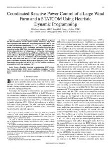
Fig. 1. Probabilistic distribution of DGs forecast errors at time .
Fig. 2. Maximum reactive power output of PV based on forecast error at time .
II. DYNAMIC REACTIVE POWER OF DGS CONSIDERING FORECAST ERRORS The maximum reactive power of a DG is limited by the current rating of the converter used for the DG. Under given real power, e.g., maximum power extraction determined by the renewable source, the capacity of the DG reactive power output is (1) where is the capacity of the DG and is the real power output of the DG. From the viewpoint of day-ahead schedules, in order to make full use of the capacity for providing voltage regulation, and reduce switching numbers of capacitor banks, while without affecting real power output, accurate forecast of real power output at next day is crucial. Errors of the forecast must be considered in the planning. This paper assumes that real power forecast errors of DGs including WT and PV obey Gaussian distribution in a day-ahead [19]–[23], as shown in Fig. 1. The probabilistic distributions of forecast errors change with time. Taking PV at moment as an example, reactive power range can be obtained as shown in Figs. 2 and 3. The probability density function, shown as the solid line in Fig. 2, is divided into intervals with a size of 1% rated power, based on which a sufficiently precious PDF can be obtained without affecting optimization. is one of the real power intervals, whose probability is shown as the dark column. The dashed line shows maximum reactive power output based on the real power. The real power output and cross the dashed line on and , shown in Fig. 2.
2474
IEEE TRANSACTIONS ON POWER SYSTEMS, VOL. 31, NO. 3, MAY 2016
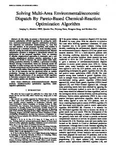
Fig. 3. Probability density function of PV reactive power at time .
The probability of reactive power interval is thus corresponding to the real power interval . The probabilistic distribution of maximum reactive power at moment is obtained after all of the intervals are calculated, shown as solid line in Fig. 3. The method obtaining PDF of maximum reactive power is a common method, which is not limited by the type of real power error PDF due to a point-by-point manner. The probabilistic distribution of forecast error changes with time, and the day-ahead scheme is optimized hourly. Therefore, 24 probabilistic distributions of maximum reactive power are made for WT and PV, respectively, which are represented as and . and are separated into intervals from 0 to , then calculates the maximum reactive power output , and the probability , for each interval, based on
(2) (3) (4) (5) where
.
III. COORDINATED PRE-COARSE-FINE OPTIMIZATION This paper aims at day-ahead reactive power optimal dispatching in distribution networks based on DG active power forecast. DG reactive power regulation ranges are determined considering active power forecast errors. Probabilistic distributions of random variables, including DG reactive power and loads, are divided into intervals. Chance constrained programming is used to obtain an optimal result under a confident level, so solution space increases geometrically. Moreover, the solution space is complex because both continuous and discrete variables are included, as well as different constraints. Therefore, solving in steps is necessary for the proposed problem. A pre-coarse-fine dynamic method is designed. First, to preliminarily optimize DG and shunt compensator outputs in
Fig. 4. Concept of overall optimization procedure.
each period, a 24-hour static optimization model is established. Hourly resolution is widely used in a day-ahead reactive power dispatching question [24], [25]. The results of the preliminary optimization will be used for the coarse optimization in order to search the optimal values in a more efficient way. Second, the reactive power scheme is refined by a 24-h dynamic coarse optimization, in which outputs of shunt compensators are optimized to reduce switching cost. However, the result from the coarse optimization is limited by the discrete feature of the shunt compensators. Therefore, a 24-h dynamic fine optimization is needed to further minimise network losses, in which DG reactive power outputs are optimized due to its fast and continuous regulation capability. Then, the coarse and fine optimizations iterate to make sure that an overall optimal result can be achieved. For an optimization process, coarse optimization is done before than fine optimization. Due to different characteristic of DG and shunt compensator outputs, coarse optimization in 24 h goes first, and then fine optimization further reduces losses in each hour based on the result of coarse optimization. The iteration between coarse and fine optimizations stops at fine optimization. A stable convergence can always be guaranteed because of similar search direction and selected initial values of iterations. Objectives in each step are coherent. At each step, the optimization objective is achieved through genetic algorithm (GA), so optimality of three steps optimization process is ensured. Fig. 4 shows the overall optimization procedure. A. Preliminary Optimization This stage sets up preliminary values of both DGs and shunt compensator outputs. The switching cost of shunt compensators is not considered because only static results are needed. Chance constrained programming [26] is a kind of stochastic programming in which the constraints or objective function of an optimization problem contain stochastic parameters. The constraints are guaranteed to be satisfied with a specified probability at the optimum solution. In this paper, chance constrained programming is used in the optimization due to the uncertainty of DGs and loads, which are represented as probability density function. The objective of the
ZHANG et al.: COORDINATED DAY-AHEAD REACTIVE POWER DISPATCH IN DISTRIBUTION NETWORK BASED ON REAL POWER FORECAST ERRORS
preliminary optimization is to minimise losses. The objective at time is formulated as follows: (6) (7) means decision variable, including , , where and , means the th state, is network loss under state , which is determined by , , , , and , is confidence level, is the maximum value when confidence level is not lower than , and means the probability. Equality constraints of the proposed problem are power flow calculation (8) where , are active and reactive power injection of bus , and are voltages of and , is node number, and and are real part and imaginary part of admittance matrix, is difference of phase angle and , respectively. Inequality constraints are reactive power output of WT and PV, voltage deviation, and power flow
2475
changes of network losses and switching cost. The objectives in the coarse optimization are to minimize the losses and the cost of switching. Some previous works took switching number of shunt compensators as fixed or as minimum. However, the cost of network losses may be much more than cost saving resulted from minimum switching. Moreover, due to the wear and tear on shunt compensator and occurred overvoltage and impulse current when switching, it is essential to consider switching cost at each switching to reflect the shortened lifetime of the shunt compensator. Therefore, cost per switching is used as a penalty function in the coarse optimization. Switching number and capacity of shunt compensators are optimized as variables. The reactive power from WTs and PV are fixed in the coarse optimization. The objective, including both network losses and switching cost, is formulated as follows:
(13) subject to (14) (15) (16)
(9) (10) where and are maximum reactive power outputs of PV and WT under state respectively, which have been discussed, and (11) , , and are node voltage value under where state , allowable minimum voltage value, allowable maximum voltage value, respectively. Finally (12) and are power flow in branch under state where and allowable maximum power flow, respectively. The results of the preliminary optimization are reactive power outputs of shunt compensators, WTs and PV for 24 hours separately. B. Coarse Optimization The result from the preliminary optimization is an ideal scheme for reactive power and voltage performance. However, in practice, frequent switching of shunt compensators will lead to life reduction and high operation cost [27], so the scheme produced from the preliminary optimization cannot be used in all instances. Therefore, a coarse optimization considering switching number and switching cost is used to refine the scheme. Shunt compensators are used for achieving the coarse optimization due to their large regulation capacity and discontinuous characteristic. The reactive power outputs of shunt compensators achieved from the preliminary optimization are modified based on the
where and are unit network loss cost and unit switch cost of shunt compensators, respectively, is switching capacity at node in period, is period number, which is set as 24 in this paper, is one hour, and is node voltage value. is the result of coarse optimization, which is the reactive power output of shunt compensator in node at time . C. Fine Optimization The result from the coarse optimization is limited by the discrete feature of the shunt compensators, which will cause overcompensation or under-compensation. Therefore, fine optimization is needed to further minimize network losses. DGs are used to achieve fine optimization due to their fast and continuous regulation capability. Reactive power outputs of DGs under regulation range are used as variables. Chance constrained programming is used in objective due to uncertainty of DG output. The objective at time is formulated as follows: (17) (18) Equality and inequality constraints are the same with (8)–(12). Reactive power outputs of DGs can be controlled to mitigate small load fluctuations. They also can be used to reduce switching numbers when a large regulation range of reactive power is available. In the Fine optimization process, based on reactive power output of shunt compensators which is produced in coarse optimization, DGs reactive power outputs are optimized. Then, the
2476
IEEE TRANSACTIONS ON POWER SYSTEMS, VOL. 31, NO. 3, MAY 2016
Fig. 6. Chance-constrained programming.
Fig. 5. Segmented chromosome management in preliminary optimization. A: encoding; B: crossover. C: mutation.
reactive power outputs of DGs is fed back to the coarse optimization, based on which, coarse optimization can produce better schemes of shunt compensators through this iteration. Convergence criterion is shown in (19) where
is iteration number. IV. OPTIMIZATION ALGORITHM
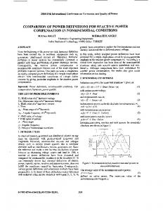
A. Genetic Algorithm The proposed pre-coarse-fine dynamic model reflects a stochastic mixed-integer programming problem, because of the discrete output from shunt compensators and random continuous output of DGs. The GA is suitable for solving such optimal problems, and the elitist strategy is used in GA to improve the convergence [11]. 1) Encoding: Discrete and continuous variables are optimized together in preliminary optimization especially. In order to optimize the variables in an efficient way, three chromosome regions are used, namely, , , as shown in Fig. 5(a). Different gene-lengths for each set of control variables are used, depending on the desired accuracy. 2) Crossover and Mutation: In order to guarantee the new chromosomes, which are produced in crossover and mutation procedures, satisfy their constraint requirements respectively, segmented chromosome management is applied in crossover and mutation procedures of preliminary optimization. For instance, , , and are crossed, and , , and are mutated to , , and respectively, as shown in Fig. 5(b) and (c). B. Chance-Constrained Programming To satisfy the confidence level of the optimal results, the objectives based on each reactive power interval are calculated. The reactive power of a WT, PV, and loads are divided into five, three, and three states in one hour, respectively, based on which a system state is divided into 45 states.
The objective values, which are calculated in each state, are arranged from the best to the worst. The probabilities are cumulated until the confidence level is achieved, and then the last objective value is used as the final result considering forecast errors of DGs real power, as shown in Fig. 6. The remaining cases will be neglected. The neglected parts could include maximum and minimum real power outputs of DGs, which may reduce the reactive power range of DGs. However, this doesn't necessarily increase network losses, because a new output scheme of shunt compensators will be made to match the curtailed range, which is more reliable. C. Flowchart of the Pre-Coarse-Fine Method A flowchart of the proposed Pre-Coarse-Fine dynamic coordinated optimal method is shown in Fig. 7. V. CASE STUDIES Two studies were conducted. Study-1 demonstrated the need of the proposed reactive power range based on active power forecast errors instead of considering only deterministic reactive power range of DGs. Study-2 is to demonstrate the superiority of proposed pre-coarse-fine dynamic coordinated optimal method. A. Simulation Conditions An IEEE 33-node distribution system embedded with DGs and shunt compensators, in Fig. 8, was used to test the method proposed for ORPD. The rated power of DGs is 200kW, and the capacity of shunt compensators for each group is 10kVar, the group number for each node is 30. The price of energy loss is [28], and the switching cost of one group capacitor bank per time is estimated as [29]. On-load tap changer (OLTC) is another important VAR source, but its adjustment will affect all the distribution lines connected to a substation bus. This paper mainly researched on the methodology of reactive power dispatch in one distribution line, so OLTC is assumed to have been determined. Actual and forecast values of wind power, PV output and loads of a practical power system in Heilongjiang Province, China were used. Forecast errors of the DGs were estimated based on history data, shown in Fig. 9. Forecast errors of load were assumed to obey a fixed Gaussian PDF in 24 h. For an Intel Core i5–3210M CPU @ 2.50GHz, 32bit, 2GB RAM computer, approximately 260 s are needed on average. This paper focused on the methodology of a coordinated dayahead reactive power dispatch considering forecast errors of DG real power in medium voltage distribution networks, which are less affected by unbalances compared with low-voltage distribution networks, so unbalances are not considered.
ZHANG et al.: COORDINATED DAY-AHEAD REACTIVE POWER DISPATCH IN DISTRIBUTION NETWORK BASED ON REAL POWER FORECAST ERRORS
2477
Fig. 9. Practical data in Heilongjiang Province, China.
Fig. 7. Flowchart of the proposed Pre-Coarse-Fine dynamic coordinated optimal method.
Fig. 8. IEEE 33-node distribution system integrated DGs and shunt compensators.
B. Study-1 Benefits for Considering Forecast Errors of DGs Real Power 1) Power Loss and Voltage Deviation: Case 1 is the scheme considering forecast errors in 80% confidence level, and case 2 does not consider forecast errors.
Output reactive power of shunt compensator at bus 26 in case 1 is larger than that in case 2 during 8:00–11:00 and 14:00–18:00, as shown in Fig. 10(a) and (b). As shown in Fig. 10(c) and (d), reactive power outputs of the WT at bus 13 and the PV at bus 23 in case 1 (solid lines) are within the available range while some in case 2 (dashed lines) are outside the range which prevents the system achieving the optimal operation. The loss cost in one day in case 1 is , and the maximum voltage deviation in case 1 is 2.08, which are lower than those in case 2, as shown in the second and third columns, Table I. Those are because real power of DGs used more power rating than forecasted in some periods due to forecast errors, so reactive power ranges of DGs become smaller, based on which reactive power outputs of DGs cannot be achieved. As shown in Fig. 10(c), the dashed line, which is the reactive power output of the WT in case 2, is out of the shaded area in 6:00–11:00, 14:00–15:00, and 19:00–24:00, which represent actual available ranges. In Fig. 10(d), the dashed line is out of shaded area in 10:00–11:00 and 15:00–16:00. In those periods, DGs can only output maximum available reactive power, but the output plan of shunt compensator in case 2 is small due to the big output plan of DGs during optimization, so the loss cost and voltage deviation in case 2 are larger. Therefore, reactive power outputs of case 1 are more reliable. The solid lines in Fig. 10(c) and (d) are all in shaded area, so the output plans of DGs in case 1 are less affected by the forecast errors. 2) Risk Indices: Risk indices [30] including risks of high loss, low voltage, and ovevvoltage are used to compare the two cases. Risk indices are calculated as the product of the severity and its probability. Network losses were used to define the severity of high-loss problem , where represents its minimum power loss when all of the reactive power is compensated locally. The percentage of voltage deviation in a distribution network was used to indicate the severity of low-voltage and overvoltage problems [31], , where and are critical conditions of low voltage and overvoltage. The probability is calculated through (4) and (5). Risk of high loss in case 1 is 0.8, which is 1.23 lower than that in case 2, and the risk of low voltage and over voltage in case 1 is 0.066, which is 0.285 lower than that in case 2, as shown in the second and third columns of Table II. Those are because reactive power outputs from controllable sources, shunt compensator,
2478
IEEE TRANSACTIONS ON POWER SYSTEMS, VOL. 31, NO. 3, MAY 2016
TABLE I INDICES COMPARISON OF CONSIDERING FORECAST ERROR
TABLE II INDICES COMPARISON OF CONSIDERING FORECAST ERROR
TABLE III INDICES COMPARISON OF DIFFERENT SOLUTION METHODS
Fig. 11. Results during iterations.
Fig. 10. (a) Reactive power output of shunt compensator in case 1 (b) Reactive power output of shunt compensator in case 2 (c) Reactive power output of WT (d) Reactive power output of PV.
accounted for a greater proportion, and DGs outputs become more reliable after considering forecast error. 3) Indices Comparison of Different Solution Methods: The above discussions are based on the assumption that the shunt compensator follows the output plan all of the time even when output plans of DGs cannot be achieved due to the forecast errors. If the shunt compensators increase one more switching when reactive power output of the DGs is not available due to large
real power forecast errors and remain the new output until the next scheduled switching, the network loss will be reduced but switching cost will be increased. The total costs will be increased because forecast errors of DGs’ real power vary in every period. The new output of shunt compensators do not march with DGs in subsequent hours, as shown in case 3; see Table III. If the shunt compensators change the output in every hour, which is further away from optimal operation, although the loss cost is reduced, the total costs will be increased more significantly due to the increase of operation cost, which reflects the decrease the life cycle of reactive power compensator devices, as shown in case 4 of Table III. C. Study-2 Benefits for Using Pre-Coarse-Fine Dynamic Coordinated Optimal Method The results during iterations of proposed pre-coarse-fine method are shown in Fig. 11. The total cost reduces quickly from to through the preliminary optimization, then approaches the optimal value through nine iterations. The utilization rate of DGs reactive power is the ratio of DGs reactive power output to the maximum available reactive power at same time, which is shown as shaded in Fig. 11.
ZHANG et al.: COORDINATED DAY-AHEAD REACTIVE POWER DISPATCH IN DISTRIBUTION NETWORK BASED ON REAL POWER FORECAST ERRORS
TABLE IV INDICES COMPARISON IN DIFFERENT OPTIMIZATION METHOD
2479
patch has been obtained in order to increase the utilization rate of DG reactive power, and reduce loss costs and switching costs of shunt compensators. An IEEE 33-node distribution system embedded with DGs and shunt compensators was used to test the proposed method and algorithm. The results of test cases show that low/over voltage and high loss were avoided. Comparing with conventional optimal methods, total costs of power losses and switching were reduced. ACKNOWLEDGMENT
Index comparisons in different optimization methods are given in Table IV, in which case case 5 seeks minimum loss, case 6 seeks minimum switching number, and case 7 combines both of them comprehensively in one step using expectation values. The switching cost in case 5 is , and the utilization rate of DGs is the lowest. This is because shunt compensators are switched frequently under constraints, and DG reactive power outputs are ignored for the small capacity. The switching number in case 6 is minimized but the loss cost is much bigger than others because loads fluctuate in every period, and DG reactive power output cannot balance all of the short of reactive power. In case 7, the switching cost and loss cost are between the previous two cases, but the total cost is smaller. However, the result in case 7 is just a compromise, and the index in the proposed pre-coarse-fine method is better, as shown in Table IV. The iterations between coarse and fine optimizations search the optimal results many times, and interact each other, based on which utilization rate of DGs is increased. Comparing with conventional optimal methods, total costs of power losses and switching were reduced from to by per day in the 4549 kVA system. Therefore, better coordination is achieved through the proposed Pre-Coarse-Fine method. VI. CONCLUSION By considering real power forecast of DGs, reactive power ranges are better determined and used for day-ahead reactive power dispatch of distribution networks. In particular, errors of real power forecast have been used to estimate probability distribution of reactive power outputs available for achieving optimal power flow and reducing network losses. A pre-coarse-fine adjustment method is proposed to consider reactive power output limits of DGs, as well as the switching lifecycle of shunt compensators. DG output capacity is considered in coarse optimization of reactive power supply of shunt compensators. Therefore, switching number can be reduced, which can prolong the equipment service life and reduce the costs of shunt compensators. In the fine optimization, DGs can be fully regulated to balance the deviation of reactive power because an initial shunt compensator scheme which has been produced before the fine optimization. Therefore, lower network losses and voltage deviations can be achieved. Multiple iterations between the discrete shunt compensators regulation and the continuous DG regulation are used to achieve coordination. Therefore, the overall optimal reactive power dis-
All data created during this research are openly available archive at http://dx.doi.org/10.17035/d.2015.100108. REFERENCES [1] K. Zehar and S. Sayah, “Optimal power flow with environmental constraint using a fast successive linear programming algorithm: Application to the algerian power system,” Energy Conv. Manag., vol. 49, no. 11, pp. 3362–3366, 2008. [2] K. Hur and S. Santoso, “On tow fundamental signatures for determining the relative location of switched capacitor banks,” IEEE Trans. Power Del., vol. 23, no. 2, pp. 1105–1112, Apr. 2008. [3] S. Deshmukh, B. Natarajan, and A. Pahwa, “Voltage/VAR control in distribution networks via reactive power injection through distributed generators,” IEEE Trans. Smart Grid, vol. 3, no. 3, pp. 1226–1234, 2012. [4] L. Zhang, W. Tang, M. Bai, and P. Cong, “Optimal configuration of generalized power sources in distribution network based on chance constrained programming and bi-level programming,” (in Chinese) Autom. Electric Power Syst., vol. 38, no. 5, pp. 50–58, 2014. [5] S. Tewari, C. J. Geyer, and N. Mohan, “A statistical model for wind power forecast error and its application to the estimation of penalties in liberalized markets,” IEEE Trans. Power Syst., vol. 26, no. 4, pp. 2031–2039, Nov. 2011. [6] K. Zou, A. P. Agalgaonkar, and K. M. Muttaqi, “Distribution system planning with incorporating DG reactive capability and system uncertainties,” IEEE Trans. Sustain. Energy, vol. 3, no. 1, pp. 112–123, Jan. 2012. [7] T. Niknam, M. R. Narimani, and R. Azizipanah-Abarghooee, “Multiobjective optimal reactive power dispatch and voltage control: A new opposition-based self-adaptive modified gravitational search algorithm,” IEEE System J., vol. 7, no. 4, pp. 742–753, Dec. 2013. [8] A. Rabiee and M. Parniani, “Voltage security constrained multi-period optimal reactive power flow using Benders and optimality condition decompositions,” IEEE Trans. Power Syst., vol. 28, no. 2, pp. 696–708, May 2013. [9] A. Ahmidi et al., “A multilevel approach for optimal participating of wind farms at reactive power balancing in transmission power system,” IEEE. Syst. J., vol. 6, no. 2, pp. 260–269, Jun. 2012. [10] Y. J. Kim, S. J. Ahn, and P. I. Hwang, “Coordinated control of a DG and voltage control devices using a dynamic programming algorithm,” IEEE Trans. Power Syst., vol. 28, no. 1, pp. 42–51, 2013. [11] Y. Y. Hong and Y. F. Luo, “Optimal VAR control considering wind farms using probabilistic load-flow and gray-based genetic algorithms,” IEEE Trans. Power Del., vol. 24, no. 3, pp. 1441–1449, Jul. 2009. [12] A. Borghetti, M. Bosetti, and S. Grillo, “Short-term scheduling and control of active distribution systems with high penetration of renewable resources,” IEEE Syst. J., vol. 4, no. 3, pp. 313–322, Sep. 2010. [13] S. Paudyal, C. Cañizares, and K. Bhattacharya, “Optimal operation of distribution feeders in smart grids,” IEEE Trans. Ind. Electron., vol. 58, no. 10, pp. 4495–4503, Oct. 2011. [14] S. Gill, I. Kockar, and G. Ault, “Dynamic optimal power flow for active distribution networks,” IEEE Trans. Power Syst., vol. 29, no. 1, pp. 121–131, Feb. 2013. [15] Z. S. Zhang, Y. Z. Sun, D. W. Gao, J. Lin, and L. Cheng, “A versatile probability distribution model for wind power forecast errors and its application in economic dispatch,” IEEE Trans. Power Syst., vol. 28, no. 3, pp. 3114–3125, Aug. 2013. [16] Y. Yang and G. Li, “A new method for space-time decoupling of distribution network dynamic reactive power optimization,” Power Syst. Protection and Control, vol. 38, no. 21, pp. 39–43, Nov. 2010.
2480
IEEE TRANSACTIONS ON POWER SYSTEMS, VOL. 31, NO. 3, MAY 2016
[17] C. Yang, B. Zhang, and F. Tao, “Two-phase optimization method of multi period reactive power and voltage control,” High Voltage Eng., vol. 9, pp. 104–109, 2007. [18] H. Tan, L. Zhang, P. W. Cong, W. Tang, G. F. Geng, D. C. Yang, and X. L. Li, “Day-ahead reactive power schedule for distribution network considering the coordination of distributed generations and capacitors,” Power Syst. Technol., vol. 38, pp. 2590–2597, Sep. 2013. [19] N. Chen, Z. Qian, I. Nabney, and X. Meng, “Wind power forecasts using Gaussian processes and numerical weather prediction,” IEEE Trans. Power Syst., vol. 29, no. 2, pp. 656–665, May 2014. [20] Z. Ziadi, M. Oshiro, and T. Senjyu, “Optimal voltage control using inverters interfaced with PV systems considering forecast error in a distribution system,” IEEE Trans. Sustain. Energy, vol. 5, no. 2, pp. 682–690, Jun. 2014. [21] F. Bouffard and F. D. Galiana, “Stochastic security for operations planning with significant wind power generation,” IEEE Trans. Power Syst., vol. 23, no. 2, pp. 306–316, May 2008. [22] M. Fan, V. Vittal, G. T. Heydt, and R. Ayyanar, “Probabilistic power flow analysis with generation dispatch including photovoltaic resources,” IEEE Trans. Power Syst., vol. 28, no. 2, pp. 1797–1805, May 2013. [23] H. Bludszuweit, J. A. Dominguez-Navarro, and A. Llombart, “Statistical analysis of wind power forecast error,” IEEE Trans. Power Syst., vol. 23, no. 3, pp. 983–991, Aug. 2008. [24] H. M. Ma, K. F. Man, and D. J. Hill, “Control strategy for multiobjective coordinate voltage control using hierarchical genetic algorithms,” in Proc. IEEE Int. Conf. Ind. Technol., Dec. 2005, pp. 158–163. [25] Y. P. Agalgaonkar, B. C. Pal, and R. A. Jabr, “Distribution voltage control considering the impact of PV generation on tap changers and autonomous regulators,” IEEE Trans. Power Syst., vol. 29, no. 1, pp. 182–192, Jan. 2014. [26] H. Yu, C. Y. Chung, K. P. Wong, and J. H. Zhang, “A chance constrained transmission network expansion planning method with consideration of load and wind farm uncertainties,” IEEE Trans. Power Syst., vol. 24, no. 3, pp. 1568–1576, Aug. 2009. [27] J. Su, A Heuristic Slow Voltage Control Scheme for Large Power Systems. Pullman, WA, USA: Washington State Univ., 2006. [28] X. L. Meng, L. M. Zhang, P. W. Cong, W. Tang, X. H. Zhang, and D. C. Yang, “Dynamic reconfiguration of distribution network considering scheduling of DG active power outputs,” in Proc. Power System Technol. Int. Conf., 2014, pp. 1433–1439. [29] Y. J. Zhang and R. Zhen, “Optimal reactive power dispatch considering costs of adjusting the control devices,” IEEE Trans. Power Syst., vol. 20, no. 3, pp. 1349–1356, Aug. 2005. [30] J. Hazra and A. K. Sinha, “Identification of catastrophic failures in power system using pattern recognition and fuzzy estimation,” IEEE Trans. Power Syst., vol. 24, no. 1, pp. 378–387, 2009. [31] M. Ni, J. D. McCalley, and V. Vittal, “Online risk-based security assessment,” IEEE Trans. Power Syst., vol. 18, no. 1, pp. 258–265, 2003. Lu Zhang (S’13) was born in Beijing, China, on February 10, 1990. He received the B.S. degree in electrical engineering from China Agricultural University, Beijing, China, in 2011, where he is currently working toward the Ph.D. degree at the College of Information and Electrical Engineering. His main research interests include voltage and reactive power control in distribution networks, renewable energy generation and hybrid AC/DC distribution networks.
Wei Tang (M’13) received the B.Sc. degree from Huazhong University of Science and Technology, Wuhan, China, in 1992, and the Ph.D. degree from Harbin Institute of Technology, Harbin, China, in 1998. From 1998 to 2000, she was a Post-doctor with Harbin Engineering University. Currently, she is a Professor with the College of Information and Electrical Engineering, China Agricultural University, Beijing, China. Her research interests include distribution network economic and security operation, distributed generation, and active distribution network.
Jun Liang (M'02–SM'12) received the B.Sc. degree from Huazhong University of Science and Technology, Wuhan, China, in 1992, and the M.Sc. and Ph.D. degrees from China Electric Power Research Institute, Beijing, China, in 1995 and 1998, respectively. From 1998 to 2001, he was a Senior Engineer with China Electric Power Research Institute. From 2001 to 2005, he was a Research Associate with Imperial College, London, U.K. From 2005 to 2007, he was a Senior Lecturer with the University of Glamorgan, Wales, U.K. Currently, he is a Reader with the School of Engineering, Cardiff University, Wales, U.K. His research interests include FACTS devices/HVDC, power system stability and control, power electronics, and renewable power generation.
Pengwei Cong (S’13) was born in Shandong, China, on September 22, 1989. He received the B.S. degree in electrical engineering from China Agricultural University, Beijing, China, in 2012, where he is currently working toward the Ph.D. degree at the College of Information and Electrical Engineering. His main research interests include reconfiguration in distribution networks with distributed generation.
Yongxiang Cai was born in Guizhou, China, on November 8, 1991. He received the B.S. degree in electrical engineering from China Agricultural University, Beijing, China, in 2014, where he is currently working toward the M.Sc. degree at the College of Information and Electrical Engineering.