International Journal of Signal Processing, Image Processing and Pattern Recognition Vol.9, No.3 (2016), pp.71-88 http://dx.doi.org/10.14257/ijsip.2016.9.3.07
Copy-Move Image Forgery Detection using Frequency-based Techniques: A Review Anuja Dixit1 and R. K. Gupta2 1 2
Madhav Institute of Technology & Science, Gwalior, 474005, India Madhav Institute of Technology & Science, Gwalior, 474005, India 1
[email protected],
[email protected] Abstract
Digital images are inseparable part of our life. Images are used at various places like medical imaging, crime scene investigation, forensic analysis, courts etc. but due to ubiquitous accessibility of image editing software, images are no longer trusted. Digital images are losing their credibility. For checking authenticity of digital images forgery detection methods are required. One of the most frequent image forgery is copy-move. In this forgery, a region of the original image is used for producing a manipulated image by performing post-processing operations over copied segment before pasting it to original image. The main principle of finding such type of forgery is based on finding resemblance present in different segments of image. Image is divided in blocks then feature vectors are extracted corresponding to different blocks of image. Sorting techniques are applied to find similarity between blocks. In case of natural images which may have similar regions, shift vectors are calculated to decrease false matches. Several methods are suggested by researchers to detect such type of forgery. In this paper, a survey on frequency-based methods is presented for detecting copy-move forgery in images. Keywords: Block-based methods, Copy-move forgery, Digital forensic, Feature extraction, Image forgery, Lexicographic sorting
1. Introduction Human brain is more susceptible to visual images. An image is much more effective than thousands of words. We believe on what we see. Due to advancement in information technology, digital images are available everywhere. Various tools are available for processing images. Tools like Photoshop and Corel draw are able to perform tampering over images and these changes cannot be detected through naked eyes. Even non-professionals having very little knowledge about these tools can make changes to image which are hard to identify. Although, most of the individuals use these tools for beautification of images but these can also be used to make significant changes in image which results in false interpretation. Forged images can be used at various places like news report, magazines and websites to mislead persons. So, for avoiding such situations various methods are developed to examine authenticity of images. Copy-move forgery used at various places because of its difficult detection. Many researchers invented different methods for detecting copy-move forgery. Digital image forgery detection methods can be divided in two broad categories: active and passive approach. Active approach requires anterior information about the image. Active approaches demands watermark or generation of signatures at the time of image acquisition. Due to this requirement, active approaches limit their applications [1, 2]. Passive approaches are also known as blind forgery detection [3] methods because these methods do not require any prior information about image. Passive approaches are divided in five categories which are Pixel-based, Format-based, Camera-Based, Source Camera Identification-based, Physics-based and Geometry-based.
ISSN: 2005-4254 IJSIP Copyright ⓒ 2016 SERSC
International Journal of Signal Processing, Image Processing and Pattern Recognition Vol.9, No.3 (2016)
Pixel-based: These techniques are based on differentiating pixel values of image to identify anomalies present in input image. Such techniques are categorized into Cloning, Splicing and Resampling. Format-based: These methods are concerned about image format. Especially, these techniques used in JPEG Format. Such kind of approaches are divided in Double JPEG, JPEG Blocking and JPEG Quantization. Camera-based: When an image is captured from a camera it goes through various image processing procedures. These kind of techniques are based on detecting image forgery on the basis of Color Filter Array, Camera Response, Sensor imperfections and Chromatic Aberrations. Source Camera Identification-based: These techniques are based on finding forgery in images on the basis of specification of camera used for capturing image. This technique is divided in three categories which are Lens Aberration, Sensor imperfections and CFA interpolations. Physics-based: These methods are based on finding forgery in image by analyzing different illuminating environment in which image was captured. These techniques divided in three categories: Light Directions (2D), Light Directions (3D) and Light Environment. Geometry-based: These methods are based on position of objects and their measurement relative to source camera. Such techniques are divided in two categories which are based on principal point and metric measurements. This paper is organized as follows. In Section 2, image forgery techniques are discussed. In Section 3, copy-move image forgery detection steps are explained. Different frequency-based methods for copy-move image forgery detection are introduced in Section 4. Finally, this review paper is concluded in Section 5.
2. Digital Image Forgery Techniques Digital image forgeries [4, 5] can be classified into five categories: Copy-move, Image Retouching, Image Splicing, Morphing and Enhancing. Copy-Move: In this technique, a part of image is copied. Copied part is pasted at some other location on the same image to hide objects of image or to bring additional objects in the image which alters message conveyed by the image. Image Retouching: This technique is used for commercial and aesthetic uses. Retouching is done for enhancing features of an image. This forgery technique can also be used for degrading features of an image. Image Splicing: In this forgery, components of different images are used for producing a single composite image. Objects of several images are juxtaposed on a single image. Morphing: In this kind of forgery, similar type of objects present in two images are used for turning original object into different object. Such forgery technique is performed to change faces present in image. Enhancing: In this kind of image manipulation, several enhancement operations (like color changes in image, blurring the background of image etc.) are performed over the image to make objects more visible.
72
Copyright ⓒ 2016 SERSC
International Journal of Signal Processing, Image Processing and Pattern Recognition Vol.9, No.3 (2016)
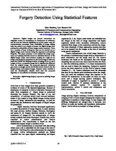
3. Copy-Move Forgery Detection As region duplication is performed in copy-move forgery so at least two similar region will be present in tampered image. Copied segment will have similar properties like noise components, dynamic range and color palette maintaining compatibility to rest of the image. Copy-Move forgery detection can be divided into two categories: Block-based [7] and Key point based methods. In block-based methods, input image is divided in fixed size overlapping or non-overlapping blocks. Generally, Square blocks are used but some researchers also used circular blocks. Features are extracted from each block using several methods such as intensity-based, moment-based, dimensionality reduction-based, frequency-based etc. Similar feature vectors are configured to find similar regions of image. In key point based methods, key points are scanned and features are extracted corresponding to these key points. Similar feature vectors are identified to find altered region present in image. In this category, image is not divided in fixed size blocks. 3.1. General Steps for Copy-Move Forgery Detection In copy-move image forgery, strong correlation between copied and pasted parts exist which is exploited for finding tampering present in image. The workflow used for finding forgery is shown in Figure (1). The steps [7] followed for forgery detection are as follows: Preprocessing: The purpose of preprocessing is enhancement in image data. Color conversion is performed if there is requirement to convert color image in gray scale image. Different preprocessing functions are applied like resizing input image, dimension reduction, filtering image with low-pass filter. In both block-based and key point based techniques, preprocessing can be applied. Feature Extraction: In this step, feature vectors are extracted. If block based method is used then image is divided in overlapping or non-overlapping blocks of fixed size. These blocks can be square or circular. Features are extracted corresponding to each block of image. In case of key point based methods, feature corresponding to key points are extracted. Matching: After feature extraction, matching between feature vectors is performed for finding similar regions present in an image. In block based methods, lexicographical or radix sorting is used for arranging similar features in proximity to each other. Best-Bin-First searching procedure is used for identifying approximate nearest neighbor which helps in feature matching for key point based methods. Filtering: Filtering procedures are used for reducing number of false matches. Morphological operations are applied to remove isolated regions.
4. Frequency-based Methods for Copy-Move Image Forgery Detection 4.1. DCT-based Method Fridrich, Soukal and Lukas [8] used a method using DCT (Discrete Cosine Transform) for image forgery detection. DCT converts spatial domain in discrete frequency domain. DCT is capable of representing data with few coefficients.
Copyright ⓒ 2016 SERSC
73
International Journal of Signal Processing, Image Processing and Pattern Recognition Vol.9, No.3 (2016)
Input Image Preprocessing
Block-based methods
Key point-based methods
Feature Extraction Moment-based Intensity-based Frequency-based Dimensionality Reduction-based
Lexicographical sorting Matching Radix sort Filtering DCT
Morphological operations
QCD DWT DyWT LBP PHT FMT Curvelet Figure 1. Steps Followed in Copy-Move Image Forgery Detection 4.1.1. Preprocessing: If input image is colored then it is converted into grayscale image applying standard formula shown in Eq. (1). I= 0.299R+0.587G+0.114 B
(1)
4.1.2. Feature Extraction: Input image is divided in Square blocks of dimension B B. A square size window slides from top left corner to bottom right corner. DCT coefficients are calculated corresponding to each block also known as feature vector.
74
Copyright ⓒ 2016 SERSC
International Journal of Signal Processing, Image Processing and Pattern Recognition Vol.9, No.3 (2016)
4.1.3. Matching: Feature vectors corresponding to blocks are stored in a matrix. If input image is of dimension M N then matrix will have (M-B+1 (N-B+1) rows and B B columns. All feature vectors are lexicographically sorted. Matching blocks are identified but there may be large number of false matches. For avoiding such situations, shift vectors for similar blocks are calculated. Coordinates of upper left corner of blocks are considered as its position. Counter value T increased by one whenever similar shift vector is obtained. Let, two block pairs with same feature vectors. Position coordinate of block pairs are ( and ( . Shift vector corresponding to similar blocks can be calculated as shown in Eq. (2). sh = (
)=(
)
(2)
As both shift vectors and represent similar shifting so shift vectors are normalized. Shift vectors multiplied with -1 so that >=0. For each matching block pair with similar normalized shift vectors, counter value T is increased by one as shown in Eq. (3). T(
)=T(
) +1
(3)
At first counter value is initialized to zero. Counter value shows the frequency of different shift vectors. This method detects all normalized shift vectors whose frequency is greater than a user specified threshold Th: T ( ) > Th for all r = 1, 2, . . . , p. Shift vectors whose occurrence frequency greater than user specified threshold corresponding block pairs are labeled as copy-move forged blocks. If threshold value is high then small size matching blocks may be left undetected but if threshold value is low then too many false matches will occur. Block size and threshold „Th‟ decides the minimum size of the forged block that could be detected by the algorithm. 4.1.4. Limitation: This method cannot perceive the difference between forged and large texture areas present in a natural image. 4.2. DWT-based Method A method proposed by Zhang, Feng and Su [9] is based on DWT (Discrete Wavelet Transform). Due to multi resolution characteristic, wavelet transform is applied over image for decomposition. DWT is able to reduce size of image at each level of decomposition. If a square image is of size at level L then at level L+1 image size will be . At each level, input image is decomposed into four sub bands. HL, LH and HH are horizontal, vertical and diagonal components of the image, respectively. LL is known as approximation or coarse level component. LL sub band is further divided in four sub images after applying decomposition. These sub images are able to restore original image if they are combined. As DWT holds iterative decomposition property. If the decomposition level is L then matching executed at LL sub-band denoted as . After every iteration, images used for generating overlapping blocks are . is coarse level image. 4.2.1. Preprocessing: If input image is color image, convert it into gray scale image using Eq. (1). 4.2.2. Feature Extraction: Sub-band is divided in overlapping blocks of size B B. Pixel values are extracted corresponding to each block and stored in a row vector. If input
Copyright ⓒ 2016 SERSC
75
International Journal of Signal Processing, Image Processing and Pattern Recognition Vol.9, No.3 (2016)
image is of size M , matrix storing feature vectors of each block will have (MB+1) (N-B+1)) rows and columns. Number of rows reduced to ( ) ( B+1). Where, j is a positive integer showing level of decomposition. 4.2.3. Matching: Lexicographical sorting is applied for finding similar feature vectors. For adjacent feature vectors, shift vector is calculated. Threshold value is set for shift vector counters. Block pairs having shift vector counter value greater than threshold are labeled with different color to identify copy-move forged blocks. 4.2.4. Limitation: This method depends on the location of copied and pasted parts. It cannot be applied over input images where forged region is situated about the center. In such cases, algorithm recursively applied over sub images. 4.3. FMT-based Method Bayram, Sencar and Memon [10] proposed a method based on FMT (Fourier Mellin Transform). In their method it is assumed that when a segment is copied from image, it undergoes several operations like scaling, rotation or blurring before pasting segment over same image. FMT is invariant to translation, rotation and scaling. Suppose a block and block after performing rotation, scaling and translation block is . Where .( ), and shows translation, rotation and scaling parameters, respectively. Blocks goes through following procedure:
Fourier transform for each block is calculated as shown in Eq. (4), it ensures translation invariance. (4)
|
Magnitude value obtained after Fourier transform resampled into log-polar coordinates using Eq. (5). |=
(5)
Log-polar values are projected on 1-D using Eq. (6). (6)
Here,
Two halves of
is computed only for are added together as shown in Eq. (7). (7)
Values of
is quantized and 45 features are obtained.
4.3.1. Feature Extraction: Input image is divided in overlapping blocks of dimension . If image size is .Total number of blocks will be . Now, for each block features are extracted using FMT. Matrix „A‟ stores all feature vectors of blocks so matrix dimension will be . Where, F is the number of columns equal to length of feature vector. 4.3.2. Matching: Similar block pairs will have similar feature vectors. Lexicographical sorting is applied which results in positioning of similar feature vectors in neighborhood of each other. This process is computationally expensive because it takes
76
Copyright ⓒ 2016 SERSC
International Journal of Signal Processing, Image Processing and Pattern Recognition Vol.9, No.3 (2016)
steps. So, to reduce complexity counting bloom filters are used. In this approach, hashes corresponding to features are calculated as shown in Eq. (8). An array R is formed having r elements whose values are initialized to zero. Hash value of these features represents the index number in array K. Hash value of similar features will occupy the same index and these values will be incremented by one using Eq. (9). (8) (9) If array R contains value higher than 2, it shows similar block pairs of image. Distance between pair of blocks is calculated as shown in Eq. (10). Let two blocks are and having top left corner positions ( ) and ( ), respectively. (10) Counter value is initialized to zero. Whenever, similar distance between pair of blocks is obtained its value increased by one using Eq. (11). (11) Blocks for which counter value is greater than threshold those block pairs are labeled as copy-move forged blocks. 4.3.3. Limitation: Their method is robust against several post-processing operations like blurring, noise addition, scaling, JPEG compression, translation etc. FMT based method cannot detect tampered blocks rotated greater than . Blocks with scaling more than could not be detected. 4.4. PHT-based Method Leida Li, Shushang Li and Jun Wang [11] proposed a new algorithm for copy-move image forgery detection. They used PHT (Polar Harmonic Transform). This transform is used for finding forgery in image having forged blocks with rotation. Orthogonal moment used for achieving features of blocks. Matching between blocks is configured with help of features of adjacent blocks. This method is not only able to cope up with conventional image processing techniques but also to geometric transformation. Polar Harmonic Transforms are harmonic in nature. These transforms are basic waves. PHT also known as circular Harmonic Transform. PHT is defined on unit circle and have orthogonal invariant property [12, 13]. PHT is able to provide unlimited number of features. Most of the time, orthogonal moments can be determined by mapping image on harmonic kernel functions which is denoted by (r, ) as shown in Eq. (12). For a unit circle, the kernel function is combination of two components: Radial and angular. (r, ) =
(r)
(12)
Where, Radial component is (r) and angular component is denoted by . By using kernel function, orthogonal moment of an image I(r, ) can be calculated using Eq. (13). (13) Where, n shows order of PHT and l shows the repetition value of PHT. „ ‟ Is a constant value and shows the complex conjugate of orthogonal kernel function.
Definition of PHT: PHT is represented using three different kernels. These are Polar Cosine Transform (PCT), Polar Sine Transform (PST) and Polar Complex Exponential Transform (PCET). Invariance property of PST is best [14] among these three forms. Kernel function of PST can be defined as shown in Eq. (14).
Copyright ⓒ 2016 SERSC
77
International Journal of Signal Processing, Image Processing and Pattern Recognition Vol.9, No.3 (2016)
(14) Where, is a radial component. Further, PST having repetition „l‟ and order „n‟ for image I (r, ) can be represented as shown in Eq. (15) (15) Where, n= 1… and |l|= 0, 1…
and
PST for a digital image I(x, y) can be achieved using Eq. (16). (16) Where, dimension of an image is M
.
Invariant Property of PST: If an image I (r, ) is rotated by an angle in clockwise direction, then moment of original image and moment of rotated image establish a relation as shown in Eq. (17). (17) Magnitude of both original and rotated moment satisfy the property | shows that PSTs are rotation invariant.
|= |
|. It
4.4.1. Preprocessing: If input is a color image convert it into gray scale using Eq. (1). 4.4.2. Feature Extraction: In this algorithm, we divide input image in fixed size overlapping circular regions. The size of circular region is , where „r‟ represents radius of circular region. Adjacent overlapping circular blocks will have only one different row or column. If Input image size is M . Total number of circular blocks will be . In next step, features are extracted from each circular block using PHT. These features are stored in a row vector corresponding to each block. As corresponding to each block, feature vector is calculated so matrix „A‟ will have number of rows. 4.4.3. Matching: For enhancing computational efficiency, lexicographical sorting is performed over the matrix so that similar feature vectors could be adjacent to each other. In their method, three threshold value are used which are representing the distance threshold, similarity threshold and area threshold value, respectively. For finding similarity between feature vectors Euclidean distance is calculated. The Euclidean distance between two feature vectors is calculated as shown in Eq. (18). (18) Where, represents the different rows of matrix A. In their method, Euclidean distance is set as 2.1. For reducing the rate of false matches, distance threshold value is set as 10. An image will not have large similar areas until there are large flat areas present in image for example cloud, sky etc. In [15] Luo stated that an image will only be considered copy-move forged if the similar area on the image is larger than 0.85% of the size of image. In their algorithm, is set as 0.85%. Further, to decrease the probability of false matches morphological operations are used. 4.4.4. Limitation: Their algorithm is able to detect forged blocks if they are orthogonally rotated. If copied regions of images are rotated at arbitrary angles then this method does
78
Copyright ⓒ 2016 SERSC
International Journal of Signal Processing, Image Processing and Pattern Recognition Vol.9, No.3 (2016)
not give ideal results but can show forged areas. This method does not yield good result when the copied region go through scaling and local blending before pasting. 4.5. DyWT-based Method Muhammad, Hussain and Bebis [16] proposed a copy-move image forgery detection method based on DyWT. Many methods are implemented based on DWT. when a segment is copied and pasted at different location on the same image then there will be different representations for similar blocks. So, there is a requirement of such descriptor which is shift invariant. Shift invariant property not possessed by DWT because of down sampling. Due to this, DWT does not yield appropriate results for signal analysis applications such as detection of edges, denoising and texture analysis. DyWT is shift invariant. Let I be the input image which is to be decomposed. Q[k] and R[k] are low and high pass filters, respectively. DyWT of input image can be computed by applying following algorithm. Starting from w=0, assume , Scaling and wavelet coefficients are calculated at scales w=1,2,…....,W using Eq. (19) and Eq. (20). (19) (20) and are the filters obtained by placing number of zeros between terms of Q[k] and R[k]. DyWT can be performed by using filters as shown in Figure (2) and Figure (3). At scale zero which is assumed as starting i.e., . In case of DyWT, no down sampling is involved. In presence of two dimensional signals four sub-bands are obtained corresponding to an image which are LL, LH, HL and
Figure 2. One level Decomposition of DyWT HH. An image can be decomposed using DyWT by applying it over rows and columns as shown in Figure (3). 4.5.1. Preprocessing: If input image is a color image then it is converted to gray scale image. Their method can also be applied to color images without requiring any conversion to gray scale. Color input image is decomposed into three color channels Red (R), Green and Blue (B). Similar steps are performed over all three channels individually and match is found by comparing lists. 4.5.2. Feature Extraction: DyWT is applied over input image as shown in Figure (4). Four sub bands are obtained but only two of them LL1 and HH1 are used for further processing to detect copy-move image forgery. LL1 sub-band is obtained after applying low pass filter in both horizontal and vertical direction so represents low frequency components of image. HH1 contains high frequency components information such as noise and sharp edges. HH1 sub-band is obtained after applying high pass filter in both horizontal and vertical directions. LL1 and HH1 are divided in overlapping blocks of dimension with 8 overlapping pixels in both row and column. It is assumed that forgery size is at least pixel.
Copyright ⓒ 2016 SERSC
79
International Journal of Signal Processing, Image Processing and Pattern Recognition Vol.9, No.3 (2016)
(LL) Column (LH) Row (HL) Column (HH) Figure 3. For a 2D Image One Level Decomposition of DyWT 4.5.3. Matching: LL1 sub band contains similarity between copy and moved segments. Due to image forgery, noise patterns of forged regions get distorted. For hiding traces of tampering, various operations are applied such as smoothing edges or adding noise around forged regions. In HH1 sub band, forged blocks possess high dissimilarity. Similarity between blocks of image is computed using Euclidean distance as shown in Eq. (21). (21) Shows the distance between blocks u and v. and are gray level values. Total number of pixels of blocks are represented by N. In their method, N is taken as 256. Distance calculated between blocks are normalized on scale 0 to 1. The distance values in List1 for LL1 sub-band are arranged in increasing order. As we deal with similarity between block pairs in List1 so all block pairs with distance value (Th1) >0.7 are discarded. In opposite to it, List2 is arranged in decreasing values of distance between block pairs. As List2 is concerned about dissimilarity between block pairs so all distance values (Th2) Th1.
Discard block pairs with Distance value < Th2.
Find matching block pairs at similar position in both lists.
Label Copy-move forged blocks
Figure 4. Detection of image forgery using DyWT 4.6.2. Feature Extraction: Consider a block of square size . This block slides all over the image from top left corner to the bottom right corner of the image dividing it into overlapping blocks. A matrix stores row vector corresponding to each block having number of rows equal to . DCT is applied over each block to extract features. To reduce the length of feature vector QCD is applied. Using QCD, feature vector length reduced to . Matrix of size will be formed.
Copyright ⓒ 2016 SERSC
81
International Journal of Signal Processing, Image Processing and Pattern Recognition Vol.9, No.3 (2016)
4.6.3. Matching: Lexicographical sorting is performed over rows of matrix A to obtain similar feature vectors in adjacent to each other. Shift vectors are calculated for pair of blocks having similar feature vectors. Whenever, counter value for a specific shift vector is greater than threshold value then block pairs are shown as copy-move forged blocks. 4.6.4. Limitation: This method cannot detect tampered region if copied segment of image undergoes rotation, heavy compression and scaling before pasting it to same image. 4.7. LBP-based Method Leida Li, Shushang Li and Hancheng Zhu [18] proposed a novel method for copymove forgery detection. LBP is rotation invariant uniform pattern. LBP belongs to graylevel texture operator. These image textures are in form of spatial structures. Local neighborhood of gray-level image with texture T can be determined as joint distribution of gray level values of pixels of image as shown in Eq. (22). (22) Where, central pixel having gray value and its neighbor pixels having gray level values . has the coordinate and coordinates of neighbors are given by . Figure (5) shows examples for symmetric neighbors in circular shape for different values of . Gray value of central pixel can be subtracted from gray values of circular symmetric neighborhood as shown in Eq. (23). (23) It is considered that values of Eq. (23) can be represented as Eq. (24).
are not dependent on
, so (24)
Figure 5. Neighbor Set which are Circularly Symmetric with Different Values. (a) (b) (c) From [19] we know that distribution of central pixel texture is not related to its local image texture so it does not provide important data for analyzing texture. Hence, Eq. (24) can be approximated as Eq. (25). (25) Various patterns which lies in neighborhood of pixels in K-dimensional histogram recorded by highly discriminative textural operators. For the region with slow slope on the edge, this operator stores difference in direction of gradient and zero values by the edge, and for every spot different directions are available. The change in mean luminance cause no effect over signed difference which states that joint distribution
82
Copyright ⓒ 2016 SERSC
International Journal of Signal Processing, Image Processing and Pattern Recognition Vol.9, No.3 (2016)
difference is invariant against change in gray-scale. So, approximate values can be obtained rather their exact values as shown in Eq. (26). (26) Where, When each binomial factor is achieved for every sign s ( - ). Eq. (26) can be converted to for describing image texture related to spatial structure by following Eq. (27). (27) The value of Z for a LBP pattern is described with help of number of times spatial transitions occur (which changes between 0 and 1) for the pattern. (28) For example, for a LBP pattern has Z value of 2 and has Z value of 3. From [19], it is known, if any LBP pattern has Z value of at most 2 then such patterns are called uniform patterns. Uniform patterns of local image texture are essential patterns. In [20], an example is shown with uniform patterns having K=8. . Number of different output values are generated for operator. When operator mapped to different output values will be generated equal to . In , superscript shows uniform patterns not having Z value larger than 2. From [20], it is known that for rotated version large number of uniform patterns exists (total number of 1 in pattern remain same). A new pattern which is rotation invariant can be defined as following Eq. (29) (29) Where, has output values. Suppose image is operated with pattern for each pixel shown by a histogram as given in Eq. (30).
is a texture image. When , then complete region can be (30)
P is the total number of of image blocks is used.
independent output values (K+2). For showing feature
4.7.1. Preprocessing: Their method can only be applied to gray scale images. If input image is color image convert it into gray scale image using Eq. (3). If image passes through signal processing operations then high feature components does not remain stable in such situations. Low frequency features of an image are more stable. For extraction of low frequency features if low pass filter is applied more than two times then detection performance increases. For detecting forged regions, input image is divided in circular blocks which are overlapping having diameter . Blocks in adjacent have only one different row or column. Suppose, input image is of size . Total number of blocks in image are . 4.7.2. Feature Extraction: Local Binary Pattern is used for feature extraction which is rotation invariant. For a given image of size , LBP will be applied over
Copyright ⓒ 2016 SERSC
83
International Journal of Signal Processing, Image Processing and Pattern Recognition Vol.9, No.3 (2016)
circular blocks to extract features for each block. All feature vectors stored in a matrix A. As similar blocks of image will have similar feature vectors. Lexicographical sorting is performed so that similar blocks can be adjacent to each other. 4.7.3. Matching: Feature matching is performed for finding similar blocks. In their method, similar blocks are identified by using Euclidean distance. Two user defined threshold values are used which are (distance threshold) and (similarity threshold). A distance threshold is set so that only those blocks which are at a distance greater than the diameter are compared. The matching starts from first row of matrix A. For a feature present in row, the distance of rows will be calculated. Smallest distance between them is denoted by . Minimum distance can be achieved by using Eq. (31). (31) If is less than similarity threshold , corresponding block pairs will be considered as correctly matched. Locations of matching blocks are stored and similar procedure repeated for all rows of A. Position of similar blocks are stored in a set S. Forgery is identified by marking copied and forged region. In their method instead of complete block only few pixels of block pairs are marked. This technique is useful in detecting edges in detection map. Further, morphological operations are used for removing isolated regions. 4.7.4. Limitation: This method is invariant to rotation and flipping performed over copied region but not robust to detect regions rotated at different angles. 4.8. Curvelet-based Method Qiao, Sung, Liu and Ribeiro [21] proposed a method for finding copy-move forgery in images based on curvelet transform. Wavelet transform is used to represent location and spatial frequency for 1D signal. In case of 2D signals, as in digital image, curvelet transform is used to produce directional information at various scales. Curvelet transform is obtained as a result of 2D ridgelet transform applied for multiple scales. Consider an image which is denoted as , then continuous ridgelet coefficients [22] can be depicted using Eq. (32). (32) Where c is scale parameter and , is translation parameter, is orientation parameter whose range is . A ridgelet [22] can be determined using Eq. (33). (33) Where ridgelet orientation is degrees. Ridgelets remain constant in the direction of lines [22]. An input image can be decomposed into sub bands by using curvelet transform. Further, each subband divided into various blocks. For ridgelet analysis ridgelet transform is used which can be implemented by combining 1-D wavelet transform and Radon transform. Frequency domain is more favorable for applying curvelet transform for obtaining efficient results. Complex ridgelet transform is computationally complex so fast discrete curvelet transform is applied using Fourier samples. Curvelet transform which have pyramid structure shows multiple orientation corresponding to various scales. Multiple oriented representation obtained by using curvelet transform is useful in accurately identifying the duplicated regions which undergoes several post-processing operations. As multidirectional decomposition is provided by curvelet transform so it is robust against manipulations related to shifting of image segment and performing rotation over copied segment before pasting them to
84
Copyright ⓒ 2016 SERSC
International Journal of Signal Processing, Image Processing and Pattern Recognition Vol.9, No.3 (2016)
original image. If image is rotated at arbitrary angles then curvelet coefficients also rotate simultaneously. Therefore, individual orientation corresponding to a pattern remain preserved. 4.8.1. Preprocessing: If input image is compressed then first of all it is decompressed. Uncompressed image is converted to gray scale. 4.8.2. Feature Extraction: For extracting features, gray scale image is divided in overlapping blocks. Fast Curvelet Transform is applied to individual blocks. If given block B [i, j] is of dimension , curvelet transform can be achieved by using Eq. (34). (34) According to adjustment of block size, every block goes through decomposition up to 3 or 4 levels. As different scales are present so various sub-bands will be achieved. If decomposition is of 3 levels and level 1, 2 and 3 contains 1, 16 and 1 sub-band, respectively then Curvelet coefficients for 3 levels can be shown as Eq. (35) (35) For reducing dimension of feature and to avoid rotation manipulation, mean values corresponding to each sub-band is calculated. Level 1and 3 have only one sub-band so no additional processing is required. Level 2 have 16 sub-bands. Mean value can be shown as Eq. (36) (36) Features of 3 level decomposition can be achieved as Eq. (37) (37) Lexicographical sorting is applied over . Adjacent blocks will be identified using sorting as similar features lie in proximity to each other. Adjacent Transition in Sub-bands: If rotation manipulation is done over image then shifting in all sub-bands occur at same angle hence relation with adjacent sub-bands remain as it was originally. Absolute values may differ, but shifting does not cause difference in distribution of transitions. Difference between adjacent sub-band pair for level 2 can be obtained as shown in Eq. (38). (38) 4.8.3. Pattern Matching: Sorted vectors are used as descriptor of each candidate block which are rotation invariant. For pair of blocks (which are similar) Euclidean distance is calculated. Where decomposition is up to 3 levels the descriptors of level 2 is applied for measuring similarity. For calculating similarity between pair of blocks a and b Eq. (39) is used. (39) Threshold value is set for identifying copy-move bocks considering some distortions in image due to noise, rotation or compression. 4.8.4. Limitation: Their method is able to detect forged region even if copied region rotated or scaled before pasting. This method is also robust against JPEG compression but cannot be applied over compressed images, first they should be decompressed.
Copyright ⓒ 2016 SERSC
85
International Journal of Signal Processing, Image Processing and Pattern Recognition Vol.9, No.3 (2016)
5. Conclusion As copy-move forgery is one of the most popular image forgery so importance of forgery detection techniques is increasing day by day. Various image forgery detection techniques are proposed by researchers to withstand against several post processing operations applied over forged region but there is lot of scope in this field to search for methods which are robust to challenges like geometric transformations (scaling, rotation). Time complexity is major issue with forgery detection algorithms. Frequency-based techniques discussed in this paper are very efficient in forgery detection. These techniques can detect forgery even if blurring, noise addition and JPEG compression is used over image. Some methods are also robust to geometrical transformation. Many methods are available for forgery detection but still there is lot of scope to search methods which can detect copy-move forgery if copied part is compressed, overlapped or enhanced. In future, hybrid techniques can be applied for achieving more accurate results with less computational cost.
References [1] [2] [3]
[4] [5] [6] [7] [8] [9] [10]
[11] [12]
[13] [14]
[15] [16]
[17]
[18]
86
D. Kundur and D. Hatzinakos, “Digital watermarking for Tell-Tale Tamper Proofing and Authentication,” Proceedings of the IEEE, (1999) July. J. Fridich, “Methods for Tamper Detection in Digital Image,” Proceedings of ACM Workshop on Multimedia and Security, Orlando, (1999) October 30-31. B. L. Shivakumar and Dr. S. Santhosh Baboo, “Detecting Copy-Move Forgery in Digital Images: A Survey and Analysis of Current Methods,” Global Journal of Computer Science and Technology, vol. 10, no. 7, (2003), pp. 61-65. M. D. Ansari, S. P. Ghrera and V. Tyagi, “Pixel-Based Image Forgery Detection: A Review,” IETE Journal of Education, vol. 55, no. 1, (2014), pp. 40-46. S. Thajeel and G. Sulong, “A survey of copy-move forgery detection Techniques,” Journal of Theoretical and Applied Information Technology, vol. 70, no. 1, (2014), pp. 25-35. S. Sharmila, S. Prajakta and S. Hiral, “Image Forgery Detection Techniques for Forensic Sciences,” ijournals, vol. 2, no. 8, (2014), pp. 40-44. S Resmi and S Chithra, “Recent Block-based Methods of Copy-Move Forgery Detection in Digital Images,” International Journal of Computer Applications (IJCA), vol. 89, no. 8, (2014), pp. 28-33. J. Fridrich, D. Soukal and J. Lukas, “Detection of copy-move forgery in digital images”, Proceedings of Digital Forensic Research Workshop, (2003) August. J. Zhang, Z. Feng and Y. Su, ”A new approach for detecting copy-move forgery in digital images”, Proceedings of the 11th IEEE International Conference of Communication Systems, Singapore, (2008). S. Bayram, H. T. Sencar and N. Memon, “An efficient and robust method for detecting copy-move forgery”, Proceedings of the IEEE International Conference on the Acoustics, Speech and Signal Processing, (2009) April 19-24. L. Li, S. Li and J. Wang, ”Copy-Move forgery detection based on PHT”, Proceedings of the World congress on the Information and Communication Technologies, (2012). P.T. Yap, X. D. Jiang and A. C. Kot, “Two-dimensional polar harmonic trans forms for invariant image representation,” IEEE Transactions on Pattern Analysis and Machine Intelligence, vol. 32, no. 7, (2010) pp. 1259-1270. L. Li, S. Li, A. Abraham and J.S. Pan, “Geometrically invariant image watermarking using Polar Harmonic Transforms,” Information Sciences, vol. 199, (2012), pp. 1-19. L. Li, S. Li, G. Wang and A. Abraham, “An evaluation on circularly orthogonal moments for image representation,” Proceedings of the International Conference on Information Science and Technology, Nanjing, China, (2011) March. W.Q. Luo, J.W. Huang and G.P. Qiu, “Robust Detection of Region-Duplication Forgery in Digital Image,” Chinese Journal of Computers, vol. 30, no. 11, (2007), pp. 1998-2007. G. Muhammad, M. Hussain, K. Khawaji and G. Bebis, “Blind copy move image forgery detection using dyadic undecimated wavelet transform”, in proceedings of the 17th international conference on Digital Signal Processing (DSP), (2011) July 6-8. M. Ghorbani, M. Firouzmand and A. Faraahi, “DWT-DCT (QCD) based copy-move image forgery detection”, Proceedings of the 18th International Conference on Systems, Signals and Image Processing (IWSSIP), (2011). L. Li., S. Li, H. Zhu, S. Chu, J. F. Roddick and J. S. Pan, ”An Efficient Scheme for Detecting Copymove Forged Images by Local Binary Patterns”, Journal of Information Hiding and Multimedia Signal Processing, vol. 4, no. 1, (2013), pp. 46-56.
Copyright ⓒ 2016 SERSC
International Journal of Signal Processing, Image Processing and Pattern Recognition Vol.9, No.3 (2016)
[19] G. J. Liu, J. W. Wang, S. G. Lian and Z. Q. Wang, “A passive image authentication scheme for detecting
region-duplication forgery with rotation”, Journal of Network and Computer Applications, vol. 34, no. 5, (2011), pp. 1557-1565. [20] V. Christlein,, C. Riess, J. Jordan, C. Riess and E. Angelopoulou, “An Evaluation of Popular Copy-Move Forgery Detection Approaches,” IEEE Transactions On Information Forensics And Security, vol. 7, no. 6, (2012), pp. 1841-1854. [21] M. Qiao, A. Sung, Q. Liu and B. Ribeiro, “A novel approach for detection of copy-move forgery”, Proceedings of the 5th International Conference on Advanced Engineering Computing and applied science, (2011). [22] J. L. Starck, E. J. Candès and D. L. Donoho, "The curvelet transform for image denoising," IEEE Transactions on Image Processing, vol. 11, no. 6, (2002), pp. 670-684.
Authors Anuja Dixit, She is a Research scholar pursuing M.Tech from Madhav Institute of Technology & Science, Gwalior, India. She has received B.Tech degree in Computer Science and Engineering from University Institute of Engineering and Technology, CSJM University, Kanpur, India.
R. K. Gupta, He is a Professor & Head of CSE/IT Department at Madhav Institute of Technology & Science, Gwalior. He has received Ph. D. degree from Indian Institute of Information Technology and Management, Gwalior. He has received M. Tech Degree in Computer Science and Engineering from Indian Institute of Technology, Delhi, India. His area of specialization is Data Mining. He has guided several Master‟s and Ph.D. thesis.
Copyright ⓒ 2016 SERSC
87
International Journal of Signal Processing, Image Processing and Pattern Recognition Vol.9, No.3 (2016)
88
Copyright ⓒ 2016 SERSC