IEEE SIGNAL PROCESSING LETTERS, VOL. 19, NO. 3, MARCH 2012
123
Detecting Image Forgery Using Perspective Constraints Heng Yao, Student Member, IEEE, Shuozhong Wang, Yan Zhao, and Xinpeng Zhang
Abstract—In visual perception, distant objects appear smaller than those close to the observer. To insert an object into an image, properly size a foreign object is difficult, especially when there is no reference object in the same distance. To detect this type of image forgery, we present a perspective-constraint based method, with which the height ratio of two objects in an image can be determined without any knowledge of the camera parameters. Assuming that the camera is held leveled and with negligible tilt, the height ratio can be found merely by a vanishing line of the plane on which both objects of interest is situated. Once the estimated ratio exceeds a tolerable interval, a forged region is identified. Experimental results show efficacy of the method even if the images to be tested have been down-sampled or compressed with a low quality factor. Index Terms—Image forensics, image forgery detection, perspective constraint.
I. INTRODUCTION
D
IGITAL forensics is a technique for detecting image forgery. Existing approaches can be classified into two categories: trace-based and constraint-based methods. Once an image has been processed with operations such as resampling, multiple JPEG coding, and contrast enhancement, there must be some statistic irregularities left, therefore detectable with various techniques [1]–[4]. Many methods are based on the hypothesis that there is no further down-sampling or manipulation for hiding tampering traces. However, this does not hold for images downloaded from the Internet, which have usually undergone severe post-manipulations. Constraint-based methods expose image forgery using some physical or geometric relationship inherently existing in the image. Authors of [5] propose to detect inconsistency of lighting direction using illuminant constraints. In [6], composites of people are detected using the constraint that the principal points estimated from human eyes should be close to the center of a photo. Photometric consistency of illumination in shadows is often a useful constraint for finding suspicious shadows [7]. Corresponding planes in two images captured from the same scene at different positions should satisfy the planar homographic constraint. In [8], planar homography and Manuscript received September 26, 2011; revised December 19, 2011; accepted December 23, 2011. Date of publication December 30, 2011; date of current version January 12, 2012. This work was supported by the Natural Science Foundation of China (60872116, 60832010), and by the Graduate Innovation Foundation of Shanghai (SHUCX101090). The associate editor coordinating the review of this manuscript and approving it for publication was Dr. Chang Yoo. The authors are with School of Communication & Information Engineering, Shanghai University, Shanghai 200072, China (e-mail:
[email protected];
[email protected];
[email protected];
[email protected]). Digital Object Identifier 10.1109/LSP.2011.2182191
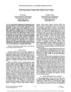
Fig. 1. (a) Camera and object in the real-word coordinates, and (b) the formed image in the pixel coordinates.
graph cut are used in automatic region detection. However, this method is invalid in a single-image case. Single view metrology [9] is used to estimate 3-D measurements in a region of interest from a single perspective view of a scene [10]. Validity of this method depends on the position, orientation and intrinsic parameters of the camera. In this letter, we propose an image forgery detection method using perspective constraints with minimal camera information. II. PERSPECTIVE CONSTRAINTS ON OBJECT HEIGHT Consider a distortion-free lens that produces 2-D images from 3-D real-world scenes. Denote a point in the real-world Euclidean coordinates and the corresponding point in the image coordinates . Assuming zero skew of the camera and isotropic characteristics of the photoelectric elements, the mapping between and is linear, and can be expressed as follows [11]:
(1) . where is a depth factor and equals to In the right-hand side of the equation, the left-most matrix is called a camera intrinsic matrix where is the focal length meathe principal point, i.e., the projecsured in pixels, and tion of camera center onto the image plane. The second matrix are rotation pais an extrinsic matrix in which and translation parameters along the rameters, and and axes respectively. In an image, an object in the distance appears smaller than if it were closer to the observer due to the perspective effect. Parallel lines converge to a point, termed a vanishing point, in the infinity. Let the optical axis of a camera be parallel to a
1070-9908/$26.00 © 2011 IEEE
124
IEEE SIGNAL PROCESSING LETTERS, VOL. 19, NO. 3, MARCH 2012
reference plane without roll and tilt, which is usually the ground, meaning that the camera is held leveled and pointed forward. Thus the line passing through the vanishing point and parallel to the ground is called a vanishing line. We now show that, when the optical axis of a camera is parallel to a reference plane, given the vanishing line and the camera height, the height of any object resting on the reference plane can be determined. Assume that an image captured by the camera is sized , with the bottom-left pixel at (1, 1) of the image coordinates, and the top-right pixel at . Let and in the world coordinates represent width, depth (distance) and height, respectively, with the reference plane at . The camera is located at where is the camera height. Consider an object sitting on the reference plane, with its top and bottom at and respectively in the world coordinates, as shown in Fig. 1(a). Since the camera is pointing forward without tilt and roll around the - and -axes respectively, the vanishing line is the intersection of the image plane and the plane parallel to the reference plane and passing through the camera center. The object is projected onto the image plane according to (1) as in Fig. 1(b). Thus, the top and bottom of the object are and in the image respectively, and the vanishing line is parallel to the -axis at . The principal point is located on the vanishing line: . Without tilt and roll, we have , and . Since the oplane is parallel to the image plane, the translation parameter and are zero. The depth factor is independent of extrinsic matrix and equals to in the absence of tilt and roll. From the above discussion, (1) can be simplified as (2)
Our aim is to find the object height . With the height of vanishing line and camera height already known, the object depth can be found according to the transformation from the bottom position in the world coordinates to its pixel coordinates : (3) Therefore, the object height
is obtained from (2) and (3): (4)
So far we have shown that, without roll and tilt, the height of an object resting on the reference plane can be determined from the vanishing line of the reference plane and the camera height. An important point here is that estimation of the object height is independent of the camera’s intrinsic parameters. This is useful in image forensics because, after being tampered, the image’s EXIF data may not be available. In most cases, camera tilt is inevitable. As indicated in [9], in such cases the height of object can still be determined from the vanishing line of the reference plane, its vertical vanishing point, and the camera height. The vertical vanishing point can be
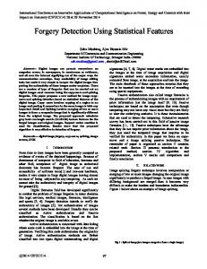
Fig. 2. Block diagram of the perspective constraint based method.
decided by at least a pair of parallel lines along the vertical direction. However, accuracy of the estimation cannot be guaranteed because the angle between two vertical lines is too small. Even worse, the vertical vanishing point is unknown if the scenes do not contain enough vertical lines. Nonetheless, our experiments show that (4) still holds approximately as long as the tilt is small enough so that the vanishing line is inside the image. III. PROPOSED METHOD Our aim is to determine whether two objects in an image have proper relationship in size satisfying the perspective rules. Therefore, we only need to find the ratio of the objects’ heights, rather than calculate their absolute heights, which are hard to get since the camera height is generally unavailable. To do so, we first draw two rectangular blocks manually that contain and fit the suspicious objects, denoted and . Let the top and bottom of these blocks be and respectively. We determine the vanishing line of a reference plane as described in Section III-A. The world height ratio of and is then determined based on the perspective constraints as presented in Sections III-B. Fig. 2 shows the overall diagram of the proposed method. A. Estimating Vanishing Line of a Reference Plane Without tilt and image cropping, the vanishing line is located at half height of the image. However, this is often not true as camera tilt and image cropping are common. An easy way to determine the vanishing line of a plane is to estimate two vanishing points from two sets of lines parallel to the plane, and construct a line passing through the two points. For simplicity, suppose a photo is shot with zero camera roll, or has been calibrated to eliminate the influence of camera roll. The vanishing line is horizontal and can be determined from a single vanishing point. Many estimation methods are available. We can roughly classify them into three types corresponding to different scenes: parallel-line based method, reference-object based method and texture-orientation based method. Parallel-line based method: Most man-made scenes contain a large amount of parallel lines such as road sides, buildings, furniture, etc. Parallel lines on the objects converge in the image. The vanishing point can be obtained from intersection of these lines. Although two parallel lines are enough for the computation, we compute the vanishing points using several parallel line segments in order to correct measurement errors. In doing so, extract a set of parallel world line segments based on edge detection and straight line extraction using Hough transform. If the angle between two lines is too small, e.g., less than 5 , one of them is discarded. Having obtained a set of edge lines, maximum likelihood estimation is used to find the vanishing point with the Levenberg-Marquardt algorithm [12]. In this method,
YAO et al.: DETECTING IMAGE FORGERY USING PERSPECTIVE CONSTRAINTS
125
lines are modified to pass a single point such that sum of squared orthogonal distances from the endpoints of the measured lines to the modified lines is minimized. This method can produce good results for clear-cut man-made scenes, but often fails when the scene lacks parallel lines. Reference-object based method: Consider a scene in which two objects and sit on the reference plane. and are used as reference objects with a known height ratio . Let the top and bottom of and in the image be and respectively, with . From (4), can be formulated as (5) where and tively. Thus,
denote the world heights of is obtained from (5):
and
respec(6)
The reference-object based method fails when there is no suitable reference object. Further, errors introduced in object height estimation with (4) may cumulate in computation. Texture-orientation based method: A locally adaptive softvoting algorithm proposed in [13] is used to resolve the abovementioned problems. The texture orientation of each pixel is estimated with a confidence score. Pixels with small confidence scores are discarded to improve accuracy. The remaining pixels are considered as voters. A certain number of pixels in the image are selected as vanishing point candidates (VPC). A local voting region for each VPC is created, and voters within this region cast their votes for the VPC. A pixel receiving the most votes is considered as an initial vanishing point, which is then updated for the scenes containing two dominant edges. When objects on the ground increase, the estimation accuracy decreases. B. Determining Height Ratio of Selected Objects As explained in Section II, with small tilt, we can roughly estimate the height of any object resting on the reference plane. Having determined a vanishing line of the reference plane, the height ratio of to , denoted , can be obtained: (7) and are the Equation (7) is derived from (4), in which world height of and respectively. The main difference between (5) and (7) is that is to be found with the given height ratio in (5), while in (7), is known and the height ratio is sought. Now we can detect image forgery by checking consistency between and the correct ratio . In many cases, can be obtained from one’s general knowledge about and , or deduced from some reference objects with known-heights having the same depth with and . This will be shown in the experiments. Assume that the estimated height ratio in authentic images obey the Gaussian distribution with a mean and variance , thus , due to measurement errors and the approximation in (7). We define a factor as a measure of consistency between and :
Fig. 3. Height comparison of selected objects from authentic images.
(8) where
is the cumulative distribution function of . , and it decreases with the increase of the distance between and . For an authentic image, the probability of being outside the interval is low. It fluctuates to the extent of that represents deviation of and . We set this probability to a constant 0.05 that gives satisfactory results in the experiments. With the constant probability, is fixed as 0.1 according to the empirical normal distribution. If is less than a predefined threshold , at least one object is considered to be a fake. To improve accuracy, several measurements of are taken and then averaged. Besides image forensics, perspective constraints can also be used to aid scene understanding, object recognition and camera calibration [14]. IV. EXPERIMENTAL RESULTS We present image forgery detection results to show efficacy of the proposed method. Figs. 3 and 4 provide examples of images before and after tampering, respectively. In Fig. 3, column (a) gives the original images, either shot by the authors or downloaded from the Internet. In the left column of Fig. 4, the top one is a suspicious picture downloaded from the Internet, and the others doctored by the authors. To demonstrate robustness of the proposed method, note that all test images, authentic or forged, have been taken with slight tilt, down-sampled and compressed with a low quality factor, representing a tough condition for image forensics. Column (b) of each figure shows manually-selected regions of objects and the estimated vanishing lines of the reference plane using the methods described in Section III-A. Objects and are enclosed in green (dashed) and yellow (solid) boxes
126
IEEE SIGNAL PROCESSING LETTERS, VOL. 19, NO. 3, MARCH 2012
real-scene images even if the images are down-sampled and degraded by low-quality compression. V. CONCLUSION Motivated by the single view metrology technique, we propose a perspective-constraint based approach to detect image forgery. The height ratio between two objects in the image is different from that in the world scene due to the perspective effect. If two objects rest on the reference plane, and their actual height ratio and the height of one object in the image are available, another object’s size in the image can be uniquely determined. The perspective constraints can be used to detect fake images even if they have been down-sampled or compressed with a low quality factor. Experimental results show effectiveness of the method. As pointed out by many authors, no single method can detect all kinds of image forgery. Methods aimed to deal with different situations are useful in the sense that they make the forgers attend to one thing and lose another. The method described here can be integrated with others such as resampling trace and illumination-constraint based methods. REFERENCES
Fig. 4. Height comparison of selected objects from fake images. TABLE I FORGERY DETECTION ON IMAGES IN FIGS. 3 AND 4
respectively. The white (dash-dotted) lines are the estimated vanishing lines. Column (c) in each figure shows an intuitive comparison of heights of and , where sizes of objects in the same image are adjusted to the same depth plane based on their estimated height ratio. It is observed that those in Fig. 4 show abnormal proportions of objects, indicating improper insertion. Consistency factors are calculated using (8) with values of and listed in Table I. A decision as whether an image is authentic or forged is made using a threshold . Experiments on more images have been done, producing similar results. It is observed that the proposed method can correctly indentify fake objects with abnormal perspective features in
[1] A. Popescu and H. Farid, “Exposing digital forgeries by detecting traces of re-sampling,” IEEE Trans. Signal Process., vol. 53, no. 2, pp. 758–767, Feb. 2005. [2] H. Farid, “Exposing digital forgeries from JPEG ghosts,” IEEE Trans. Inf. Forensics Secur., vol. 4, no. 1, pp. 154–160, Mar. 2009. [3] M. C. Stamm and K. J. R. Liu, “Forensic detection of image manipulation using statistical intrinsic ?ngerprints,” IEEE Trans. Inf. Forensics Secur., vol. 5, no. 3, pp. 492–506, Sep. 2010. [4] W. Wei, S. Wang, X. Zhang, and Z. Tang, “Estimation of image rotation angle using interpolation-related spectral signatures with application to blind detection of image forgery,” IEEE Trans. Inf. Forensics Secur., vol. 5, no. 3, pp. 507–517, Sep. 2010. [5] M. K. Johnson and H. Farid, “Exposing digital forgeries in complex lighting environments,” IEEE Trans. Inf. Forensics Secur., vol. 3, no. 2, pp. 450–461, Jun. 2007. [6] M. K. Johnson and H. Farid, “Detecting photographic composites of people,” in Proc. Int. Workshop on Digital Watermarking, Guangzhou, China, 2007. [7] Q. Liu, X. Cao, C. Deng, and X. Guo, “Identifying image composites through shadow matte consistency,” IEEE Trans. Inf. Forensics Secur., vol. 6, no. 3, pp. 1111–1122, Sep. 2011. [8] W. Zhang, X. Cao, Y. Qu, Y. Hou, H. Zhao, and C. Zhang, “Detecting and extracting the photo composites using planar homography and graph cut,” IEEE Trans. Inf. Forensics Secur., vol. 5, pp. 544–555, Sep. 2010. [9] A. Criminisi, I. Reid, and A. Zisserman, “Single view metrology,” Int. J. Comput. Vis., vol. 40, no. 2, pp. 123–148, Nov. 2000. [10] L. Wu, X. Cao, W. Zhang, and Y. Wang, “Detecting image forgeries using metrology,” Mach. Vis. Applicat., 2010, 10.1007/s00138-0100296-6. [11] D. A. Forsyth and J. Ponce, Computer Vision: A Modern Approach. Upper Saddle River, NJ: Prentice-Hall, 2002. [12] R. Hartley and A. Zisserman, Multiple View Geometry in Computer Vision. Cambridge, U.K.: Cambridge Univ. Press, 2004. [13] H. Kong, J. Y. Audibert, and J. Ponce, “General road detection from a single image,” IEEE Trans. Image Process., vol. 19, no. 8, pp. 2211–2220, Aug. 2010. [14] D. Hoim, A. A. Efros, and M. Hebert, “Putting objects in perspective,” Int. J. Comput. Vis., vol. 80, no. 1, pp. 3–15, 2008.