(XHC, YHC, ZHC), is made available to the Cognitive layer. The laser scanner perceives the distance to objects along a single horizontal line, where objects in ...
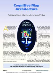
CORBYS Cognitive Control Architecture for Robotic Follower Adrian Leu, Danijela Ristić-Durrant, Siniša Slavnić, Cornelius Glackin, Christoph Salge, Daniel Polani, Atta Badii, Ali Khan, and Rajkumar Raval
Abstract—In this paper the novel generic cognitive robot control architecture CORBYS is presented. The objective of the CORBYS architecture is the integration of high-level cognitive modules to support robot functioning in dynamic environments including interacting with humans. This paper presents the preliminary integration of the CORBYS architecture to support a robotic follower. Experimental results on high-level empowerment-based trajectory planning have demonstrated the effectiveness of ROS-based communication between distributed modules developed in a multi-site research environment as typical for distributed collaborative projects such as CORBYS.
I. INTRODUCTION
I
demands for robots whose purpose is to work effectively with humans have raised the need for development of robot control architectures that enable integration of advanced robot functionalities. The objective of the Integrated Project CORBYS funded by the European Commission under the 7th Framework Program [1] is to design and implement a robot control architecture that allows the integration of high-level cognitive control modules, a semantically-driven self-awareness module and a cognitive framework for anticipation of, and synergy with, human behaviour based on biologically-inspired information-theoretic principles. CORBYS will provide a generic control architecture to benefit a wide range of applications where robots work in synergy with humans, ranging from mobile robots such as robotic followers to gait rehabilitation robots. In this paper, a preliminary realisation of the CORBYS control architecture for a robot following a human co-worker is presented. The presented preliminary realisation does not include complete high-level cognitive modules which will be integrated in the CORBYS architecture within future developments, but includes novel high-level empowerment-based trajectory planning providing inputs for low-level robot control. The integrated cognitive module uses empowerment [7], a generic, task-independent, information-theoretic NCREASING
This research was supported by the European Commission as part of the CORBYS (Cognitive Control Framework for Robotic Systems) project under contract FP7 ICT-270219. A. Leu, D. Ristić-Durrant and S. Slavnić are with the Institute of Automation, University of Bremen, Otto-Hahn-Allee 1, 28359 Bremen, Germany (e-mail:{aleu,ristic,sslavnic}@ iat.uni-bremen.de). C. Glackin, C. Salge and D. Polani are with the Adaptive Systems Research Group, University of Hertfordshire, United Kingdom (e-mail: {c.glackin2,c.salge,d.polani}@herts.ac.uk). A. Badii, A. Khan, and R. Raval are with Intelligent Systems Research Laboratory, School of Systems Engineering, University of Reading RG6 6AY United Kingdom (e-mail:{atta.badii,a.a.khan,r.raval}@reading.ac.uk).
measure, to provide an intrinsic motivation to the agent, enabling the robotic follower to modify its task-based trajectory (following the human) with the additional intrinsic motivation of maintaining the robot’s mobility and ability to influence the world, i.e., an incentive to not get stuck. The focus of the presented preliminary realisation of the CORBYS architecture is also on robot safety functionality through the implementation of a functionality supervisor module as well as a reflexive module. However, the main goal of this paper is to describe the different layers of the robot control architecture and communication across the various layers. The rest of the paper is organised as follows. Section 2 presents related work on cognitive robot control architectures. The innovative CORBYS architecture is presented in Section 3. The ROS-based communication in the CORBYS architecture is presented in Section 4. The robotic follower is presented in Section 5 which also includes experimental results on cognitive empowerment-based trajectory planning. II. ARCHITECTURES FOR COGNITIVE CONTROL OF ROBOTIC SYSTEMS
Robots capable of working in dynamic environments alongside humans need to meet new levels of cognitive capabilities such as reasoning, decision making, adaptation, goal setting, problem solving and learning in complex environments and in real-time. A growing number of robotics researchers have realised that cognitive robotic architectures are a natural way to achieve this goal of designing a robot with such general capabilities [2]. Recent research has been mainly dedicated to the use of hybrid architectures which could overcome the problems of both purely deliberative socalled Sense-Plan-Act (SPA) architectures and purely reactive architectures. SPA architectures failed to perform well because the level of cognitive tasks attempted was too complex to cope with in a real-world environment while purely reactive architectures had the drawback that while immediate reactive actions could be performed, complex tasks could not, as the necessary cognitive functions were not supported [3]. Hence, the development of hybrid architectures comprising both reactive and deliberative components was a natural progression in the design of robot control architectures. Hybrid cognitive architectures are mainly characterised by a layering of capabilities where low-level layers provide reactive capabilities, whereas high-level layers provide the
more computationally intensive deliberative capabilities. A key problem in such architectures is what kind of control framework to embed, to manage the interactions across the various layers. In this paper, the layered architecture for robot control entitled CORBYS is presented. It aims at integration of highlevel cognitive modules that support human-robot symbiotic relationships. CORBYS follows a trend of using features of ROS (Robot Operating System) [4] for developing generic architectures with effective communication between the modules. ROS simplifies software development for robots by providing a modular, scalable, and easily extendable system. A novelty of CORBYS is the standardisation of software modules through the so-called CORBYS ROS Node Template. This standardisation is of high importance in distributed multi-site development within collaborative research projects such as CORBYS. III. CORBYS ARCHITECTURE FOR ROBOT CONTROL As illustrated in Fig. 1, the CORBYS architecture is comprised of four layers: cognitive, executive, control and physical layer. Cognitive Module 1
User GUI
COG. 1
Cognitive Module N
…
COG. N
Functionality Supervisor
Task Manager
FS
Sensor Data Server
Reflexive Module
Robot Safety Controller
Cognitive Layer
TM
Executive Layer
Real-Time Control
SDS
RTC
Sensors &Actuators
Control Layer
Physical Layer
Fig. 1. Layout of layered CORBYS robot control architecture.
The Cognitive layer contains the high-level cognitive modules that enable the robot to understand the current state of the system and environment including the human operator so as to generate adequate high-level commands for the specific robotic application to be communicated to the low-level control system. These modules are supported with a multisensor system to facilitate dynamic environment perception. The Control layer is in direct connection with the physical layer where it reads sensors data and provides direct commands to the actuators. The Sensor Data Server (SDS) is responsible for providing sensor data (either as raw or processed sensor data) to the Cognitive layer while the RealTime Control (RTC) receives high-level commands from the Cognitive layer and translates them into commands that are directly executable by the actuators. The Reflexive module (RM) is also included in the Control layer in order to allow fast reflex-like behaviour in critical
situations. This module detects dangerous situations and can independently take action without the need to wait for a command from the software-based Cognitive layer. The hardware-based reflex capability in the CORBYS framework is composed of an implementation of invariant system reflexes, e.g. stopping the robot moving forward in the case that an obstacle is detected in dangerously close proximity, or for any other situations requiring immediate risk-aversive control. The Executive layer is the core of the CORBYS architecture as it is responsible for enabling the communication between the Control layer and the Cognitive layer, as well as for coordinating and supervising the overall system functionality. This layer comprises two modules: Task Manager (TM) and Functionality Supervisor (FS). The TM coordinates the overall system functionality. One of the main tasks of the TM module is to respond to instructions from the human co-worker in terms of enabling specific working modes such as starting a desired operational mode after system start-up. The TM is based on a state machine where each working mode is a state and the transitions depend on the user input, on the current working mode as well as on the state of each required module. Therefore, in order to put the system into a specific working mode, the TM first checks whether all pre-conditions are met and then determines the configuration parameters for each module based on the specific working mode. Next, the TM informs the modules about the desired change in the working mode and then remains on stand-by until all modules have completed their configuration and are ready to start. Finally, the TM enables the desired working mode. The FS monitors the state of all modules through heartbeat messages that are sent by the modules to FS at regular time intervals. In this way the FS keeps track of the health status of each module, as these heart-beats include status information, so that each module can signal whether it is functioning properly, or if some error is encountered. If a module fails to send a heart-beat within the given time interval, the FS assumes that the module malfunctions and informs the TM about the encountered problem. At the same time, if the malfunctioning module is critical for the safe functioning of the system, the FS sends a signal to the Robot Safety Controller (RSC) to trigger the emergency stop. The RSC then immediately cuts the power to the actuators. The Physical layer consists of sensors and actuators that are application and robotic system specific. In the CORBYS robotic follower, this layer is composed of mobile robot sensors and actuators. These will be presented in detail in the following sections together with other specific aspects of the cognitive control architecture for the robotic follower. IV. ROS-BASED COMMUNICATION IN THE CORBYS ARCHITECTURE
Considering the fact that multiple modules running on different computers need to communicate with each other, and that this communication has to be reliable and easy to im-
plement, the ROS (Robot Operating System) [4] was chosen in CORBYS as the communication framework, due to the advantages that it brings. Hereby CORBYS follows a trend of using features of ROS for developing generic architectures with effective communication between the modules. ROS simplifies software development for robots by providing a modular, scalable and easily extendable system. ROS facilitates communication between different modules (socalled nodes) regardless of whether they run on the same or on different computers. This allows for flexible adaptation of the robot control architecture to specific hardware layouts. The communication between the modules is carried over topics, which are virtual “one-to-many” communication channels used for data sharing. This communication protocol has been chosen for the CORBYS layered architecture as it enables asynchronous communication between the cognitive modules, which run more slowly due to the complex deliberative processes, and, the control modules that run considerably faster. Besides communication over topics, several other ROS utilities were used in the CORBYS architecture for module configuration and data logging. One of them is the parameter server, which is a shared multivariate dictionary that is used by the CORBYS TM to store configuration data for all modules. The significant advantage of this approach is that all the parameters of the various modules are stored centrally, thus facilitating the changing of the robot working mode (e.g. at system initialisation or system startup), where multiple modules need to be reconfigured at the same time. Data logging is enabled via the so-called ROS bags, which are data files that can store messages sent to specified topics. When these files are played back, the original message data flow is simulated. In this way modules can be developed and tested off-line using the recorded data so that later they can be tested with online data without any changes to the modules’ functionality. This approach enabled CORBYS developers to develop the modules of the presented robotic follower remotely without need to have the physical system on site – a critical enabler in distributed multi-site development. The off-line tests using ROS bags are followed by remote on-line tests over OpenVPN, which creates a so-called “Virtual Private Network”. This approach enables modules located at different sites to communicate with each other as if they were parts of the same local network. A. CORBYS standardisation of software modules All the software modules of the CORBYS architecture are standardised using the novel CORBYS ROS Node Template. The benefit of module standardisation is that the structure of the software module is predefined. As illustrated in Fig.1, a CORBYS module, for example, Cognitive Module 1 (COG 1), according to the CORBYS ROS Node Template contains three sections: module logic (depicted in light blue), libraries for communication with the FS and TM (depicted in red and dark blue respectively) and libraries for communication with other modules (depicted in green). Out of these three sections only the module logic is individually imple-
mented by module developers according to the specific module functionality. The other two sections are common to all modules. The section with libraries for communication with other modules is based on ROS and represents a layer between the module developer and the actual ROS communication. B. ROS-based data messages The communication between CORBYS modules is done using messages that are defined using ROS. All defined messages contain a standard header that includes, among other fields, an automatically incremented sequence number and the time stamp of when the message was sent. Besides the header, the message contains the actual data field whose content depends on the communicating modules and on the used topic. The header data is used to perform automatic tests that are not part of the standard ROS communication. Based on the sequence number, a sequence number check is automatically performed for determining whether messages were missed during transmission. Additionally the transmission times are automatically monitored based on the time stamps of the messages. These transmission times give valuable information about the network load. If either messages are lost or the transmission time is too long, a heart-beat containing the corresponding error code is automatically sent to the FS to inform about the encountered problem, who further informs the TM. In this way, the proper message delivery is automatically monitored and possible malfunctions are detected. V. THE COGNITIVE ROBOTIC FOLLOWER. The layout of the considered robotic system is shown in Fig. 2. The system has two types of sensors for environment perception: a stereo camera system and a two dimensional (2D) laser scanner. The stereo images captured by the camera system are processed by the vision module described in [5]. The processed data, in the form of a vector of human coordinates with respect to the camera coordinate system (XHC, YHC, ZHC), is made available to the Cognitive layer. The laser scanner perceives the distance to objects along a single horizontal line, where objects in the robot’s environment, other than the human, are considered as obstacles. In order to combine outputs from different sensors for the purpose of robot trajectory planning it is necessary to transform these outputs to a common coordinate frame. In the system presented here, the common coordinate frame is the world frame that is aligned to the robot frame at the robot’s starting position. The robot’s coordinate frame {Xr, Yr, Zr} is illustrated in Fig. 2 together with the camera coordinate frame {XC, YC, ZC} and the horizontal perception line of the laser ZL. As the pose of the robot’s frame with respect to the world origin changes while the robot is moving through the world, it is estimated using odometry based on the data of the incremental encoders that are placed on the robot’s differential two-wheel drive. The wheel slippage is compensated using simultaneous localization and mapping (SLAM)
based on laser data [6]. Xc Yc Zc
Cognitive PC
Sensor Data Server PC
On-Board PC
ZL
Refl. Module
Yr Xr
Zr
Fig. 2. Schematic illustrating the robotic system for following the human co-worker.
As illustrated in Fig. 2, the robotic follower has three computers: an on-board computer and two off-board computers, the Sensor Data Server computer and the computer used for the high-level cognitive empowerment-based trajectory planning. Besides the executive layer modules, FS and TM, parts of the Control layer are running on the on-board PC. These are the Real-Time Control and sub-modules of the Sensor Data Server (SDS) which capture the raw sensor data and send it for further processing to the SDS (visionbased human tracking, odometry, SLAM). Such distributed computing is necessary to avoid blocking the control system by computationally intensive sensor processing and trajectory planning, and to ensure that control commands are sent at regular time intervals. The FS and TM modules run on the on-board computer, as they need to be able to quickly react and stop the robot in case of emergency even if a network problem occurs. In order to be robust against potential network failures, FS has a direct connection to the Robot Safety Controller via a digital line, while the TM can indirectly stop the robot by signaling the emergency stop to the FS. The Reflexive Module (RM) realises the real-time reflexive responses of the robotic follower by implementing low level reactive algorithms (e.g., obstacle detection) using FPGA (Digilent Spartan 3E-1600) [12]. The RM is directly connected to the robot, so that it can immediately stop the robot if an obstacle is detected within a dangerously close proximity. Laser scanner data from an artificial rectangular area in front of the robot is processed by the RM to detect obstacles in the path of the robotic follower and to ensure the safety of the robot by stopping immediately before hitting the obstacle. This is also applicable in other real-time safety protection contexts. At the heart of the RM lies the FPGA Reflexive Layer (FRL) Core module (Hardware), which provides the core reflexive behaviour functionality, as part of the embedded system within the FPGA. Major functional logic blocks in the RM (Micro-Blaze processor and peripherals) communicate with each other via the on-chip Processor Local Bus (PLB). The major I/O of the FRL Core include the on-chip PLB, a network interface (TCP/IP) and a Heart-Beat interface with the FS. Additional to the FS functionality of re-
ceiving heart-beats from all modules as explained in Section 3, the FS sends heart-beat signals to the RM for overall health status check monitoring. Similarly, a heart-beat is also sent as output from the RM to the FS in order to inform about the RM health status. If either of these two modules detects that the other has failed to send a heart-beat, an emergency stop is immediately triggered. There is a dedicated two line digital interface with the FS to monitor the health status and a dedicated digital signal to the robot safety controller that cuts the power to the wheels. There is also Linux OS running on the embedded MicroBlaze processor that manages non-time-critical tasks such as communication data for initialising and/or updating the FRL Core reflexive memory to include additional reflexes. Major functional blocks within the FRL-Core include onchip memory for storing reflexive behaviour definitions, a heart-beat monitor and an Obstacle Detection and Avoidance (ODA) module. The on-chip memory module stores thresholds (values) related to the reflexive behaviour, for instance, the memory stores threshold values in order to create a rectangular protection field in front of the robot for obstacle detection based on laser range finder data. The ODA module implements an algorithm for reactive collision avoidance based on comparison of live data with thresholds in realtime. The X and Z coordinate values from the laser scanner are compared against pre-programmed threshold values (less than, greater than and equal to) in order to detect an obstacle within the artificial protection field. When an obstacle is detected, the ODA module sends a digital signal to the safety controller to cut the power supply to the robot wheels in order to stop the robot moving forward. A. High-level empowerment-based trajectory planning The high-level cognitive module receives sensor input from the SDS in the form of ROS data messages. The messages comprise vectors of human and robot position. In addition to this data, the cognitive module is aware of the geometry of the environment and of the position of obstacles obtained from the laser scanner. The cognitive module provides a trajectory to the RTC. The trajectory is a path which the robot follows. The path planning is calculated to realize a human following behavior, whilst maintaining controllability and mobility of the robot. The means by which this behavior is generated is using an information-theoretic formalism called empowerment [7]. Empowerment [7] provides a universal, local, task independent utility for each state the agent can be in (positions of the robot in the environment). It captures how much an agent is in control of its perceivable environment. Optimizing empowerment leads to a tendency to keep one's options open, and in the specific case presented in this paper it keeps the mobile robot from colliding with obstacles while following the human, and also prefers the agent to be in a location where it can reach the other locations easily; both properties desirable for a robotic follower. Empowerment is measured in bits, and is formally defined as the amount of Shannon information an agent can "inject"
into its sensor, by way of action selection. More formally it is defined as the channel capacity between the agents actuators and its sensors (for theoretical background refer to [7,8]). In this way, empowerment measures the effect of control actuation on the sensors, and by choosing actuation that has the maximal effect on the sensors, the robot can move in an ‘empowered’ way. The continuous nature of the robotic system requires computing empowerment in the continuous domain. Robust but time consuming approaches for this are discretization of the continuous domain via binning, or the approximation of the conditional probability between actuators and sensors as a multivariate Gaussian distribution [8]. Here, a faster approximation is used [9] that treats the relationship between actuators and sensors as multiple linear channels with added Gaussian noise. Empowerment relies on a local model that ‘knows’ how each action will affect the resulting sensor state distribution. In this way, by knowing what is the outcome of sending different wheel speed motor commands to the robot, empowerment needs to be able to calculate the resulting position of the robot in the environment (without actually performing these commands). This functionality is provided to empowerment by a Gaussian Process-based Model Learner (ML) sub-module of the cognitive module. Gaussian Processes (GP) regression is employed as GPs are a powerful tool that can provide predictive distributions. They are non-parametric, meaning that a GP is not restricted to a particular class of functions, but instead by employing the so-called kernel trick [11] can encompass all functions sharing the same degree of smoothness. The task of finding appropriate hyperparameters for multiple output GPs is computationally demanding, so for simplicity an ensemble of three multiple-input-single-output (MISO) GPs are employed in this work in a similar vein as in [8]. As illustrated by Fig. 4 there are three input (action) states S and three output (successor) states S'. The input states represent the left and right wheel speeds for the robotic follower and an additional state (used primarily for robustness of the model) which accounts for minor latencies in the receipt of the wheel speed data in the CORBYS architecture. Hence if minor latencies appear in the system, the model adapts to deal with them. More significant latencies in data communication are flagged to the FS in the CORBYS architecture via the regular heartbeat messages, triggering the RSC emergency stop procedure. The three outputs of each GP (S') are the change in X-coordinate, change in Zcoordinate, and change in orientation of the robot respectively.
Fig. 4. Illustration of a GP ensemble for learning state transition probabilities by combining multiple univariate GPs.
B. Integration results. The ML was trained offline using data collected directly from the robot in the form of ROS bags. The ROS bags contained recordings of wheel speeds, latencies, and robot position data. 950 data points were used for training and 706 unseen data points were used for testing. Testing within C++ using the Eigen linear algebra library on a typical dual core computer occurs in less than 3 seconds. Another benefit of using a GP-based ML with empowerment is that empowerment can be calculated directly from the covariance matrix of the GP [10]. Empowerment was calculated offline for regular sampling of the testing room at a resolution of 60 cm2. The obstacles identified by the RM from the laser scanner data were included as constraints in the empowerment calculation. If during the offline virtual exploration for all possible paths the empowerment module attempts to move through an obstacle, the movement is blocked, since the reflexive module in online application would stop the robot, and the resulting state is then just the initial state. Hence this possible actuation is effectively ‘pruned’ from the resulting path planning. In this way, the obstacle directly affects the empowerment measurement of the state, since it limits the robot’s mobility. The result of this offline calculation of empowerment is a map of the room containing an assessment of the utility (in bits) of the various positions of the room at the afore-mentioned resolution. Typically positions in open-space have higher utility (empowerment) than positions in corners and near obstacles. To incorporate the following behaviour the resulting empowerment map is then scaled by Euclidean distance to the human during runtime. The closer the human is to the robot the higher the scaling, except for a 1 meter `exclusion zone' around the human used for safety which is set to zero utility at all times, which makes being in that area undesirable for the robot. Generating a path towards the human, whilst avoiding obstacles, is achieved by successively finding from the robot’s current position, the next nearest highest empowered position using a simple grid search. Offline tests were later followed by online tests that were performed via the internet with the help of an OpenVPN connection that creates a Virtual Private Network, meaning that all CORBYS modules behave as if they were physically in the same local network. This allowed for rapid system development, requiring very little adjustment when all modules were actually put together and tested on-site. Fig. 5 illustrates the robot’s chosen path around the obstacles when following the human and maximizing empowerment. Even though the empowered path is not immediately necessary for keeping a distance, the position at the end of the empowered path offers the same distance to the human as the position straight behind the human, but has higher empowerment, i.e. it offers more movement options to continue the following.
testing of modules enabled by utilising ROS bags, and remote integration of different modules via OpenVPN before on-site tests. The modular approach to design and testing used in the CORBYS project, and the performed remote integration of the modules using OpenVPN, led to the fact that only a relatively small amount of time was needed to adjust the modules for successful on-site use. Hence, the CORBYS approach can be usefully applied to other complex multi-partner and multi-site projects, where the ability to do successful remote integration can significantly accelerate the final integration. REFERENCES Fig. 5. ROS (rviz) visualisation of the empowerment-based trajectory planning. The blue cuboid represents the robot, the green cuboid is the human and, the other cuboids are obstacles. The scaled empowerment values are overlaid on the floor of the room, white means high empowerment and black means low empowerment. The empowered path is coloured in red.
VI. CONCLUSIONS This paper presented the CORBYS architecture for control of robots functioning in dynamic environments alongside humans. The architecture integrates high-level cognitive modules, execution, monitoring, a reflexive module and real-time control. An overall view of the architecture was given focusing on the ROS-based communication across the modules. The standardisation of the architecture software modules using the novel CORBYS ROS Node Template has been introduced; this represents the key integration aspects of such distributed architectures. The integration of the CORBYS architecture in a robot following a human coworker was presented. The high-level cognitive module of the presented CORBYS robotic follower uses empowerment maximization-based trajectory planning which enables the robot to maneuver into a more mobile position for following the human co-worker while avoiding bad terrain. The presented results of on-site tests demonstrate the effectiveness of the CORBYS approach to the integration of distributed modules. This approach comprises off-line development and
CORBYS, Available: www.corbys.eu. D. Vernon, G. Metta and G. Sandini, “A Survey of Artificial Cognitive Systems: Implications for the Autonomous Development of Mental Capabilities in Computational Agents,” IEEE Transactions on Evolutionary Computation, vol. 11, pp.151-180, 2007. [3] R. Ross, TheSharC Cognitive Control Architecture, Technical report, 2004. [4] S. Cousins, “Welcome to ROS Topics,” IEEE Robotics & Automation Magazine, vol. 17(1), pp. 13-14, 2010. [5] E. Petrović, A. Leu, D. Ristić-Durrant and V. Nikolić, V, “Stereo Vision-Based Human Tracking for Robotic Follower,” International Journal of Advanced Robotic Systems, 2013. [6] A. Leu, D. Ristić-Durrant and S. J. Ul., “Sensor-based control of robotic follower,” in Proc. the 2nd international conference Mechanical Engineering in XXI Century, Serbia, 2013. [7] A. Klyubin, D. Polani and C. Nehaniv, “All else being equal be empowered,” Advances in Artifcial Life, pp. 744-753, 2005. [8] T. Jung, D. Polani and P. Stone, “Empowerment for continuous agentenvironment systems,” Adaptive Behavior, 19(1):16, 2011. [9] C. Salge, C. Glackin and D. Polani, “Approximation of empowerment in the continuous domain,” Advances in Complex Systems, 16(1-2):129, 2013. [10] C. Salge, C. Glackin and D. Polani, “Empowerment and Statedependent Noise -An Intrinsic Motivation for Avoiding Unpredictable Agents,” in Proceedings of the 12th European Conference on Artificial Life 2013, to be published. [11] C. E. Rasmussen, C. K. I. Williams, Gaussian Processes for Machine Learning. The MIT Press, 2005. [12] V. Ayala-Ramirez, J. A. Gasca-Martinez, R. Lopez-Padilla and R. E. Sanchez-Yanez, An Artificial Protection Field Approach For Reactive Obstacle Avoidance in Mobile Robots. In: Barrera, A. (ed.) Mobile Robots Navigation, 2010. [1] [2]