Bharathidasan Institute of Technology, Anna University. Tiruchirappalli â 24, India. D.Asir Antony Gnana Singh3. Department of CSE. Bharathidasan Institute of ...
2014 International Conference on Recent Trends in Information Technology
CORDIC Iterations Based Architecture for Low Power and High Quality DCT E. Jebamalar Leavline1, S.Megala2,
D.Asir Antony Gnana Singh3
Department of ECE Bharathidasan Institute of Technology, Anna University Tiruchirappalli – 24, India
Department of CSE Bharathidasan Institute of Technology, Anna University Tiruchirappalli – 24, India
Abstract—Discrete Cosine Transform (DCT) is widely used in image and video compression standards. This paper presents low-power co-ordinate rotation digital computer (CORDIC) based reconfigurable architecture for discrete cosine transform (DCT). All the computations in DCT are not equally important in generating the frequency domain output. Considering the important difference in the DCT coefficients the number of CORDIC iterations can be dynamically changed to reduce the power of consumption with improved image quality. The proposed CORDIC based 2D DCT architecture is simulated using Modelsim and the experimental results show that our reconfigurable DCT achieves power savings with improved image quality. Keywords—Coordinate rotation digital computer (CORDIC), Discrete Cosine Transform (DCT), Low power reconfigurable architecture.
I.
INTRODUCTION
The rapid growth of multimedia services running on portable applications demands low power and high quality implementation of complex signal processing algorithms. The applications of multimedia systems involve image and video processing and it should be implemented with low cost and low power because of limited battery lifetime.Many papers have been published on reducing power dissipation of image and video applications, especially low power design of discrete cosine transform [1]. DCT is a computation intensive operation in image and video compression. It is used in image and video compression standards such as JPEG [2], MPEG, H.263 [3] and H.264. The direct implementation of DCT requires large number of multipliers and adders. Many previous works focused on Distributed Arithmetic (DA) based DCT & multiple constant multiplications [4]. To reduce the power consumption Distributed Arithmetic (DA) is used without multiplier [5].DCT implementation using distributedr arithmetic [DA] includes several advantages such as area reduction and high speed performance. High speed can be achieved by using conventional DA implementation by pre-computing possible values and storing it in ROM. But ROM based DA has the disadvantage of redundancy which is introduced to accommodate all possible combinations of bit patterns of input signals. A regular and simple DCT architecture can be obtained by using bit serial DA based approach. MCM based DCT can be implemented with a smaller number of shifts and add operations. The well known coordinate rotation digital computer algorithm (CORDIC) proposed in 1959 [7], is widely used with 978-1-4799-4989-2/14/$31.00 © 2014 IEEE
an iterative technique. It is used for evaluating basic arithmetic operations, trigonometric, hyperbolic, singular value decomposition [8] and so on. Conventional CORDIC can be realized using addition and shift operations that is used for multiplier less power DCT architecture. In order to skip the internal CORDIC iterations, data correlations between neighboring pixels are efficiently used in low power CORDIC based DCT architecture [6]. In DCT all the computations involved in generatingthe frequency domain outputs are not equally important. In this some of the computations are more important for determining the output image quality while others play relatively less important roles. Thus the number of cordic iterations can be controlled by considering the importance of DCT coefficients by which considerable power saving can be achieved. In this work, a low power and high quality DCT architecture based on CORDIC iterations is presented in which the important difference among the DCT coefficients are efficiently exploited to achieve the power saving. The rest of the paper is organized as follows. Section II describes the related works. In section III the CORDIC based DCT architecture is described. The proposed CORDIC based DCT architecture is presented in section IV. Experimental results are discussed in Section V and the paper is concluded in section VI. II.
RELATED WORKS
Many of the multimedia applications such as video conferencing, internet, video streaming and video over wireless are most bandwidth consuming modes of communications. In order to reduce power and area low power architecture was presented in [9]. In this CSD representation for fixed point DCT coefficient and multiplier less multiplication was implemented. Also, to concentrate on image quality a CORDIC based DCT [10] was proposed. An algorithmic approach for low power design [11] was proposed based on trade off between image quality and power consumption, in order to concentrate on low power and high speed [12]. To reduce power consumption, DCT based on scalable multiplier [13] was proposed. In this method, the use of scalable and dynamically reconfigurable multipliers resulted in significant power savings.
2014 International Conference on Recent Trends in Information Technology III.
CORDIC BASED DCT ARCHITECTURE
A. CORDIC Architecture: The CORDIC algorithm is well known and widely studied iterative technique [15] for evaluating many arithmetic operations and trigonometric functions. CORDIC algorithm can be used to evaluate not only the trigonometric functions but also transcendental functions and elementary functions like square root, division, etc. The basic principle of CORDIC is to iteratively rotate a vector using a rotation matrix [14] which is represented as 1− i ⎡ xi ⎤ ⎡ xi −1 − σ i 2 y i −1 ⎤ ⎢ y ⎥ = ⎢ y + σ 21−i x ⎥ i i −1 ⎥ ⎢ i ⎥ ⎢ i −1 ⎢ ⎥ ⎢⎣ z i ⎥⎦ z − σ iα i ⎣ i −1 ⎦
(1)
In the CORDIC operation the magnitude of the rotated vector is scaled and accumulated after every iteration according to equation (2)
1 + 2 2(1−i )
(4)
Z = Ty t
where y = T × t, as a result the separable 2D DCT computation can be obtained by using 1D DCT computations. The 8 × 8 1-D DCT transform is expressed as
c( k ) 7 ⎛ ( 2i + 1) ⎞ x (i ) cos⎜ uΠ ⎟ ∑ 2 i =0 ⎝ 16 ⎠
where k = 0,1,….7
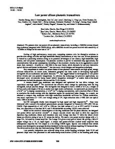
The CORDIC algorithm can operate on two different modes. The vector mode of operation is used to find the amplitude and argument of a given vector, while the rotation mode is used to obtain the sine and cosine values of the given angle [16]. The hardware architecture of the CORDIC iteration is shown in Fig 1.
1
B. CORDIC based DCT architecture: DCT express a signal in terms of a sum of cosine function with different frequencies. Based on separable property 2DDCT process is decomposed into and 1D DCT which is expressed as the following equation.
X (t ) =
where x and y are the vector co-ordinate components of x and y axes, ‘i’ is the ithiteration step, σ is the sign bit that can be +1 or -1 representing the direction of vector rotation, z is the accumulated rotation angle and α is the predefined angle value of each micro rotation stepαi = arc tan(21-i)
ki =
2
(2)
⎧1 ⎪ c(k ) = ⎨ 2 ⎪1 ⎩
k=0
(5)
Otherwise
where x(i) is the input data and x(t) is 1-D DCT transformed output data. The 1-D DCT transform is represented as follows.
⎡ X (0) ⎤ 1 ⎡C 4 C 4 ⎤ ⎡ x(0) + x(7) + x(3) + x(4)⎤ ⎢ X (4)⎥ = 2 ⎢C 4 − C 4⎥ ⎢ x(1) + x (6) + x(2) + x(5) ⎥ ⎦ ⎦ ⎣ ⎣ ⎣ ⎦ ⎡ X ( 2) ⎤ 1 ⎡C 2 ⎢ X (6) ⎥ = 2 ⎢C 6 ⎣ ⎣ ⎦ ⎡ X (1) ⎤ ⎡ C1 ⎢ X ( 3) ⎥ ⎢ 1 ⎢ ⎥ = ⎢C 3 ⎢ X (5) ⎥ 2 ⎢C 5 ⎢ ⎥ ⎢ ⎣ X (7 ) ⎦ ⎣C 7
C 6 ⎤ ⎡ x (0) + x(7) − x(3) − x (4)⎤ − C 2⎥⎦ ⎢⎣ x (1) + x(6) − x (2) − x(5) ⎥⎦ C3 C5 C7 ⎤ − C 7 − C1 − C 5 ⎥⎥ (6) − C1 C 7 C 3 ⎥ ⎥ − C 5 C 3 − C1 ⎦
⎡ x (0) − x (7 ) ⎤ ⎢ x (1) − x ( 6 ) ⎥ ⎢ ⎥ ⎢ x ( 2 ) − x (5) ⎥ ⎢ ⎥ ⎣ x (3) − x ( 4 ) ⎦
where Ck=cos(kπ/16). The cosine elements in eq.(6) can be changed into sine elements through trigonometric symmetric property, and eq.(6) can be rearranged as the following equations:
Fig. 1. Hardware architecture of CORDIC iteration
The accumulated ki value in eq.(2) is converged to a constant as,
k (n) = Π in=1 k i = Π in=1 Lim k(n) ≈ 0.60725…. n→α
1 1 + 2 2 (1−i )
(3)
where n is the number of iterations.
⎡ X (4) ⎤ 1 ⎡C 4 ⎢ X (0) ⎥ = 2 ⎢ S 4 ⎣ ⎦ ⎣
− S 4⎤ ⎡ x(0) + x(7) + x (3) + x(4)⎤ C 4 ⎥⎦ ⎢⎣ x(1) + x(6) + x(2) + x(5) ⎥⎦
⎡ X (6) ⎤ 1 ⎡C 6 ⎢ X ( 2)⎥ = 2 ⎢ S 6 ⎣ ⎦ ⎣
− S 6 ⎤ ⎡ x(0) + x(7) − x(3) − x( 4) ⎤ − C 6⎥⎦ ⎢⎣ x(1) + x(6) − x( 2) − x(5) ⎥⎦
⎡ X (1) ⎤ 1 ⎡C 7 ⎢ X ( 7) ⎥ = 2 ⎢ − S 7 ⎣ ⎦ ⎣ 1 ⎡C1 + ⎢ 2 ⎣− S1
S7 ⎤ C 7 ⎥⎦ S1 ⎤ C1⎥⎦
⎡ x(3) − x(4) ⎤ ⎢ x(0) − x(7)⎥ ⎣ ⎦ ⎡ x(2) − x(5)⎤ ⎢ x(1) − x(6) ⎥ ⎣ ⎦
− S 3⎤ ⎡ x (0) − x(7)⎤ ⎡ X (3) ⎤ 1 ⎡C 3 ⎢ X (5)⎥ = 2 ⎢ − S 3 C 3 ⎥ ⎢ x (3) − x( 4) ⎥ ⎣ ⎦ ⎣ ⎦ ⎣ ⎦ S 3 ⎤ ⎡ x(1) − x (6) ⎤ 1 ⎡C 3 \ + ⎢ 2 ⎣ − S 3 C 3⎥⎦ ⎢⎣ x(2) − x (5)⎥⎦
(7)
2014 International Conference on Recent Trends in Information Technology where Sm = sin(mπ/16) = Ck, and m=8-k. In eq.(7) more number of multiplication operation is present. In order to reduce that CORDIC technique is applied in that equation to reduce multiplication operation by using only shift and addition operations. The rearranged 1-D DCT equation is now represented as vector rotation matrix together with the consecutive CORDIC iterations as shown in Fig.2.
Table 1 shows the required iterations and vector rotation direction σ (sign bits)
TABLE I.
Required Iterations i=0,1,3,10
Directions (Sign-Bits) σ = -1,+1,+1,+1
3π/16+
i=1,3,10
σ = -1,-1,-1
3π/16*
i=1,3,10
σ = -1,+1,+1
4π/16*
i=0
σ = +1
6π/16*
i=(90o),2,3,5,7
σ = -1,+1,+1,+1, -1
7π/16+
i=0,1,3,10
σ = -1,-1,-1,-1
π/16+
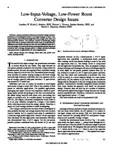
After 2-D DCT operation, the input data in spatial domain is transformed to the frequency domain which is the 8 x 8 block of 64 DCT co-efficient shown in Fig 3.
High Frequency
Less sensitive Low Frequency
Low Frequency 0 1
Fig 1.
T00 T10 T20 T30 T40 . . .
T01 T11 T21 T31 . . .
T02 T12 T22 . . .
2
3
T03 T13
4
5
T04 ….
….. …..
High Frequency 6 7
….. ….
….
Sensitivity difference of 8 x 8 2-D DCT co-efficient
REQUIRED ITERATIONS AND DIRECTIONS FOR VECTOR ROTATION
Angle
Fig. 2. Hardware architecture of CORDIC based 1-D DCT
3
For example, to rotate the vector by 7π/16, only the ith iterations (i=0, 1, 3, 10) are executed and for power savings the rest of the iterations can be skipped. The look ahead algorithm for 7 π/16 cordic rotator can be written as follows.
⎡ x ⎤ ⎡1 ⎢ y⎥ = ⎢ −10 ⎣ ⎦ ⎣σ 10 2
σ 10 2 −10 ⎤ ⎡1 σ 3 2 −3 ⎤ ⎥ ⎢ ⎥ −3 1 1 ⎦ ⎣σ 3 2 ⎦
⎡1 σ 1 2 −1 ⎤ ⎡1 ⎢ ⎥ ⎢ −1 −0 1 ⎣σ 1 2 ⎦ ⎣σ 0 2
σ 0 2 −0 ⎤ ⎡ x 0 ⎤ 1
⎥ ⎢ ⎥ (8) ⎦ ⎣ y0 ⎦
where σ0 = -1, σ1 = -1, σ3 = -1, σ10 = -1 In table 1,i = 900 represents the optional first iteration of the CORDIC [14]. The numbers of iterations for our DCT architecture are carefully selected such that the error between the desired angle and the corresponding accumulated angle does not exceed 0.004 for all the given angles. TABLE II.
CORDIC SCALE FACTOR AND THEIR APPROXIMATION VALUES
Based on signal compaction property of DCT, the lower frequency components have more signal energy of the outputdata compared to that of high frequency components. After the quantization [17], the high frequency DCT coefficient becomes even smaller, this means that the lower frequency components are more sensitive to human eyes than high frequency components. This is due to the that fact the low frequency DCT co-efficient are more important compared to that of high frequency components. CORDIC based DCT architecture is designed considering the important difference between DCT coefficients. A large number of CORDIC iterations are assigned to generate the low frequency DCT coefficients of iterations are used for the high frequency components. IV.
PROPOSED LOW POWER CORDIC BASED DCT
In the proposed low power CORDIC based DCT architecture, to generate DCT coefficients, different number of iterations are assigned and the number of iterations need to be carefully selected in order to get the minimum error between the desired input angle and corresponding accumulated angle.
π/16
Desired ScaleFactor 0.3137856…….
2-2 + 2-4 + 2-10
3π/16
0.4437599…….
2-1 - 2-4 + 2-7 – 2-9
4π/16
0.3535533…….
2-2 + 2-4 + 2-5+2-7 + 2-9
6π/16
0.4810759…….
2-1 - 2-6 - 2-8
7π/16
0.3137856…….
2-2 + 2-4 + 2-10
Angle
Approximation Value
The scale factor is decided according to the number of the executed CORDIC iterations. As the number of iterations is known ahead, the scale factors are pre determined as in Table II. One interesting observation is that the look ahead CORDIC using less number of iterations has the similar effect when the high shift terms are removed from the look ahead CORDIC. For example, if the CORDIC rotation with 7π/16 is executed using three iterations (i=0, 1, 3) the look ahead CORDIC algorithm and its corresponding scale factor are as follows. x = (1-2-1-2-3-2-4)x0 + (1+2-1+2-3-2-4)y0
(9)
2014 International Conference on Recent Trends in Information Technology y = (-1-2-1-2-3+2-4)x0 + (1-2-1-2-3-2-4)y0
(10)
4
shown in table 4. The power consumption is measured with 50 MHz clock cycles, 2.5V supply voltage.
k7π/16 = 0.3137856 In eq.(8) when the higher shift terms (smaller than 2-10 terms) are eliminated, the equation is changed to eq.(9) andeq.(10). A. Reconfigurable Cordic Based DCT Architecture As mentioned earlier in this paper, the high shift term of the look ahead CORDIC can be carefully removed which has the same effect with the less number of CORDIC iterations.The lesser number of CORDIC iterations means the CORDIC with low computational complexity. To further reduce the power consumption, we propose a reconfigurable CORDIC based DCT architecture. The proposed reconfigurable architecture can dynamically change the CORDIC iterations. Generally in the look ahead CORDIC, the shift terms for calculating low frequency DCT coefficients i.e., terms for calculating X(0), X(1) in [7] are more important than the shift terms for calculating high frequency co-efficient. In look ahead CORDIC equation low shift terms are more important whereas the high shift terms are less important. To save the computation power, the least important shift term X (7) is removed. To calculate X(3) component both the CORDIC rotators of 3 π/16 and π/16 are needed and those are expressed as the following look ahead CORDIC equation in the normal mode. x7π/16* = (1-2-1-2-3+2-4-2-10) x0+ (1+2-1+2-3-2-4-2-10) y0 (11) xπ/16+ = (1+2-1+2-3-2-4+2-10)x0+(1-2-1-2-3-2-4-2-10)y0 (12)
TABLE III.
COMPONENT REQUIREMENT FOR VARIOUS MODES
Normal Mode
Gate count Adder Sub tractor Multiplier TABLE IV. Power consumption Power(mw)
Mode 1
232 296 96
Mode 2
176 264 96
112 128 96
POWER CONSUMPTION AT DIFFERENT MODES
Normal mode 0.186
VI.
Mode 1 0.185
Mode 2 0.184
CONCLUSION
CORDIC is a powerful algorithm and a popular algorithm of choice when it comes to various digital signal processing applications. In DCT architecture, all the computations are not equally important in generating the frequency domain outputs. This paper presented a low power CORDIC based DCT architecture, where the differences in DCT coefficients are efficiently exploited to allocate the number of CORDIC iterations. The reconfigurable CORDIC based DCT architecture can dynamically change the modes with 1power savings and improve image quality. The device utilization summary showed that minimum resources were consumed. This idea can assist the low power design of image and video compression applications.
The scale factor in normal mode k3π/16* = 2-1 - 2-4
(13)
kπ/16+ = 2-1 + 2-4
(14)
For mode 1, 3π/16 CORDIC rotator is reduced as follows. x’3π/16 = (1-2-1-2-3-2-4) x0 + (1+2-1+2-3-2-4) y0(15) As it goes to the higher level the number of shift terms are further reduced. V.
EXPERIMENTAL RESULTS OF THE PROPOSED LOW POWER CORDIC BASED DCT ARCHITECTURE
In this section, the experimental results of the proposed CORDIC based DCT architecture are presented. In this, the number of CORDIC iterations is selected according to the target angle. The power consumption for DCT architecture is measured with 50 MHz clock cycles, 2.5 V supply voltage. The power consumption for three different modes is calculated. Because some of the higher order shift terms in CORDIC iterations can be removed considering the important difference of DCT co efficient, our proposed DCT architecture shows the lowest gate count and power consumption with improved image quality. The component requirement for our DCT architecture for various modes is given in table 3. In this the amount of adder, sub tractor, and multiplier required for three different modes of DCT architecture is given.The power consumption for our DCT architecture at different modes is
REFERENCES [1]
Min Woo Lee, Ji Hwan Yoon, Jongsun Park, “Reconfigurable CORDIC based low power DCT architecture based on data priority”, IEEE Transactions on VLSI, 2013. [2] T. Acharya and P. Tsai, ‘JPEG2000 Standard for Image Compression: Concepts, Algorithms and VLSI Architectures’ J. Wiley & Sons. NJ, 2005. [3] F.H.P. Fitzek, M. Reisselein, ‘MPEG-4 and H.263 Video Traces for Network Performance Evaluation’ IEEE Network, vol.15, No.6, pp 4054, Nov/Dec 2001. [4] Vijay Kumar, K.K. Mahapatra and Umesh C. Pati “An efficient distributed arithmetic based VLSI architecture for DCT”, IEEE Transactions on VLSI, 2011. [5] Byoung-II Kim and Sotirios G. Ziavras, “Low power Multiplier less DCT for Image/video Coders” IEEE 13th International Symposium on consumer Electronics, ISCE’09, pp 133-136, 2009. [6] H. Jeong, J. Kim, W.K. Cho, “Low power Multiplier less DCT Architecture using Image data correlation”, IEEE Transaction on consumer Electronics vol. 50 No.1 pp 262-267, Feb 2004. [7] J.E. Volder “The CORDIC trigonometric computing technique”, IRE Transactions on Electron. Comput., vol.8. n o. 3, pp. 330-334, sep 1959. [8] S. Hsiao and J. Delosme, ‘Parallel singular value decomposition of complex matrices using multidimensional CORDIC algorithms,’ IRE Trans. Signal Process. vol.44, no.10, pp.993-1001, 1996. [9] Muhammad Faisal Siddiqui, Raja Ali Riaz, Syed Saud Naqvi ‘Low Power and Area Efficient DCT Architecture For Low Bit Rate Communication’, 2012. [10] B.Heyne, C.C.Sun, J.Goetze, And S.J.Ruan ,”A Computationally Efficient High Quality Cordic Based DCT’,2006.
2014 International Conference on Recent Trends in Information Technology [11] Jogsun Park And Kaushik Roy’A Low Power Reconfigurable DCT Architecture To Trade Off Image Quality For Computational Complexity, IEEE, 2004. [12] Syfiq Al-Atiiq, Gilang Ilham And Ardiantto Satriawan ‘A Low Power And Fast Dct/Idct Architecture Using Proposed Loeffler CSD-CSE Algorithm’ [13] Ricardo Castellanos, Hari Kalva and Ravi Shankar’ Low Power DCT Using Highly Scalable Mulipliers’, IEEE, 2009. [14] Jack E. Volder, “ The CORDIC Trignometric Computing Technique”, IRE transactions on Electronic computers, Vol. EC-8, 1959, pp.330-334.
5
[15] John S.Walther, “A unified Algorithm for Elementary functions”, Spring Joint Computer Conference Proceedings, Vol. 38, 1971, pp.379-385. [16] P.K. Meher, J.Valls, T.Juang, K.Sridaran, and K. Maharatna “50 years of CORDIC”, IEEE trans. Circuit Syst. I, Reg. papers, vol. 56, no. 9, pp. 1893-1907, Sep. 2009. [17] G.K. Wallace, ”The JPEG still picture compression standard,” IEEE Trans. Consum. Electron. vol.38,no.1,pp.18-34,Feb.1992.