10.2478/v10048-011-0004-3
MEASUREMENT SCIENCE REVIEW, Volume 11, No. 1, 2011
Correction of ADC Errors by Additive Iterative Method with Dithering M. Kamenský, K. Kováč Department of Measurement, Faculty of Electrical Engineering and Information Technology, Slovak University of Technology, Ilkovičova 3, 81219 Bratislava, Slovak Republic,
[email protected] The iterative method could be used for automatic accuracy improvement of a measurement system. In its application for analogto-digital converter (ADC) a quantization error represents a limitation for the correction process. Therefore, combination of correction methods is common for ADC error correction. Combination of the additive iterative method (AIM) with nonsubtractive dithering (ND) has been proposed for slow measurement based on ADC where errors could change in time. The principle of combination of both techniques is described in the paper. AIM is based on precise inverse element (IE). In the designed system the IE output signal is created by pulse width modulation and low-pass filtering. A technique similar to deterministic dithering is employed to achieve precise processing of signal from IE. Analysis of influence of stochastic dither upon the results of correction is performed with the aim to find optimal parameters of ND. Finally, dependency of the root mean squared error and error dispersion on the measured value is drawn to show how AIM corrects the nonlinear deterministic error but slightly increases system noise. Keywords: Iterative Correction, Dithering, ADC error
1. INTRODUCTION
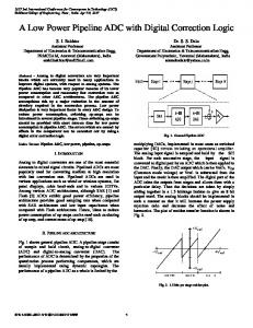
help of auxiliary means. Generally, for the AIM three new blocks should be added to MT and then four main blocks of the system are distinguished (Fig.1). In our case the designed measurement system consists mainly of integrated components of a single-chip microcomputer: MT – in our system is represented by ADC; block of processing (BP) – CPU (processor) with memory; inverse element (IE) – pulse width modulation (PWM) circuits with RC-filter; switch – multiplexer (MUX).
F
OR PRECISE measuring through the whole life-cycle of a measurement device many special error correction methods have been developed. In the connection with this trend self-correction functions are becoming very important in modern equipments. Very often an analog-to-digital converter (ADC) integrated within a monolithic microcontroller is used for signal level measurements. Then ADC characteristics determine the overall metrology properties of a measuring channel. Generally it is not difficult to make a correction of offset and gain error of ADC. More sophisticated methods based on look-up table [1] offer fast correction of ADC error nonlinearities. But if an error could change in time, methods with self-correction features should be applied. If a microcontroller or other universal system building component is used in a measurement channel, usually several hardware elements stay redundant. Frequently, those are DAC or PWM outputs. At such situation the additive iterative method (AIM) of correction could be employed with advantages. This correction naturally suppresses the linear error. But it is suitable also for ADC with nonlinearities. AIM requires precise inverse element (IE) for correction of both nonlinear and linear error of the general analog measurement transducer (MT). However, quantization limits the efficiency of AIM, therefore in the designed measurement system AIM is combined with dithering. We prefer nonsubtractive dithering (ND) for this application where low price is an important aspect. Both stochastic and deterministic dithering techniques are used in the designed measurement system as discussed bellow.
d sm
+
s
SW
w
MT h()
MEMORY
o
BP ok
wIE AIM
IE hIE()
ok
Fig.1. Block diagram of our measuring system, the part in frame corresponds to AIM.
For our application only slow changes of measured value sm are assumed. This value will be considered constant during one correction process and it represents the mean of actual system input sm=E[s]. Time duration of the correction depends on the response of IE discussed later, on error value and on the number of steps. For precise evaluation of sm, dither d is added before AIM. So in the initial step of AIM, signal s=sm+d is connected to the input of MT. Corresponding MT output h(sm) is then sent from BP to IE ok,0=h(sm). At the same time BP changes the state of SW. Therefore in the next steps signal from IE wIE= hIE(ok) is being sent to the input of MT. Every next input to IE is solved in BP from the actual MT output oi and previous IE input ok,i-1 according to the following iterative formula
2. THE PRINCIPLE OF ITERATIVE CORRECTION One of the ways for measurement accuracy improvement is the use of the so-called structural-algorithmic methods [2], where the measurement errors are diminished with the
o k ,i = o k ,i −1 + o k , 0 − o i
15
(1)
MEASUREMENT SCIENCE REVIEW, Volume 11, No. 1, 2011
If the characteristic of IE is ideal, i.e. it is equal to inverse of ideal MT characteristic hIE-1= hI, the described algorithm decreases the static error of MT Δh(sm)=h(sm)-hI(sm) according to geometric series Δhk,i = (-C)iΔh. Factor C is determined by ratio of derivatives (sensitivities) of error and ideal characteristics [3] and if the condition of convergence is satisfied |C|