Institute for Communications Systems ICS, University of Surrey, Guildford, UK. â . School of ... and support efficient radio resource control (RRC) procedures.
Correlation-based Adaptive Pilot Pattern in Control/Data Separation Architecture Abdelrahim Mohamed∗ , Oluwakayode Onireti∗ , Muhammad Imran∗ , Ali Imran† , Rahim Tafazolli∗ ∗ Institute † School
for Communications Systems ICS, University of Surrey, Guildford, UK of Electrical and Computer Engineering, University of Oklahoma, Tulsa, USA E-mail: abdelrahim.mohamed @ surrey.ac.uk
Abstract—Most of the wireless systems such as the long term evolution (LTE) adopt a pilot symbol-aided channel estimation approach for data detection purposes. In this technique, some of the transmission resources are allocated to common pilot signals which constitute a significant overhead in current standards. This can be traced to the worst-case design approach adopted in these systems where the pilot spacing is chosen based on extreme condition assumptions. This suggests extending the set of the parameters that can be adaptively adjusted to include the pilot density. In this paper, we propose an adaptive pilot pattern scheme that depends on estimating the channel correlation. A new system architecture with a logical separation between control and data planes is considered and orthogonal frequency division multiplexing (OFDM) is chosen as the access technique. Simulation results show that the proposed scheme can provide a significant saving of the LTE pilot overhead with a marginal performance penalty. Index Terms—Base station; channel estimation; control data separation architecture; correlation; LTE; OFDM; physical layer; pilot; signalling overhead
I. I NTRODUCTION Nowadays, requirements and performance targets of fifth generation (5G) cellular systems are becoming of increasing interest in academia and industry fora. These include a peak data rate in the order of 10 Gbps with 1 ms latency [1]. Meeting these ambitious targets requires addressing several issues that include signalling overhead. Traditionally, all cellular users are connected to the same base station (BS) irrespective of their activity state (i.e., active, idle or detached) provided that they are within the footprint of this BS. Thus the same physical layer (PL) frame is used by all user equipments (UEs) and hence most of the control signals are cell-specific rather than user-specific resources. For example, the cellspecific reference signal (CRS) of the long term evolution (LTE) is used as a pilot by the active and the idle UEs for channel quality measurements and for channel estimation to allow coherent demodulation of control and data channels. In addition, it is used in the initial access phase to demodulate the broadcast channel [2]. Since channel conditions of the detached and the idle UEs are usually unavailable, these signals are distributed in the resource grid based on the worst-case scenario, e.g., high mobility assumptions [3]. Although this approach guarantees acceptable performance for all users including those in severe conditions, it over-provisions the PL frame under moderate or good channel conditions [4]. Some proposals to reduce this
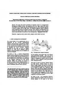
overhead are being considered such as using several classes of pilots with each class being transmitted at the necessary rate, e.g., high rate UE-specific reference signal (UE-RS) for data detection and low rate channel state information reference signal (CSI-RS) for link adaptation measurements [5]. Nonetheless, these signals also have a static pattern constrained by the worst-case conditions. This calls for the design of an adaptive frame structure with dynamic allocations. Although such techniques may not be suitable in conventional cellular systems, a new system architecture that separates the control plane (CP) and the data plane (DP) could allow adopting these mechanisms. In this paper, we develop an adaptive pilot pattern scheme by considering a control/data separation architecture (CDSA). By means of simulations, we show that the proposed scheme provides a significant overhead reduction as compared with the LTE CRS pattern. The reminder of this paper is structured as follows: Section II describes the CDSA and investigates its applicability for implementing adaptive signalling mechanisms. Section III develops the proposed adaptive pattern while Section IV provides simulation results. Finally, Section V concludes the paper. II. C ONTROL /DATA S EPARATION A RCHITECTURE The key concept behind this architecture is to separate the signals required for full coverage from those needed to support high rate data transmission. A few macro cells, also known as control base stations (CBSs), provide the coverage and support efficient radio resource control (RRC) procedures. Within the CBS footprint, data services are provided by dedicated small cells known as data base stations (DBSs) [6]. As shown in Fig. 1, all the UEs are anchored to the CBS for basic connectivity services, e.g., system information, paging, channel requests, etc. while the active UEs are associated with both the CBS and the DBS in a dual connection mode [7]. The DBS is invisible to both the detached and the idle UEs and its on-demand connection with the active UEs is established and assisted by the CBS. This relieves the DBS from the task of transmitting cell-specific signals and removes the constraints imposed by the unknown channel conditions of the detached/idle UEs. Expressed differently, the DBS needs to consider channel conditions of the active UEs only. As a result, the DP pilot signal can be considered as a UE-specific resource and its transmission rate/pattern can be adaptively
Typical OFDM Tx chain
Typical OFDM Rx chain Training resources extraction
DBS
CBS
CBS DBS idle UE
DBS
CFR estimation at training resources
DBS active UE
Transmitter
Receiver Correlator
Broadcast-type/cell-specific signalling: coverage and mobility management Noise compensation
Data and adaptive unicast-type/UEspecific signalling, e.g., pilots Adjust pilot pattern
New pilot pattern
Fig. 1. Control/Data separation architecture
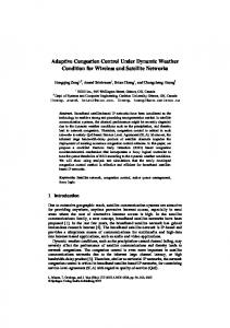
adjusted according to the temporal channel conditions reported by the active UEs. Similarly, the cyclic prefix and other signals can be adaptively and flexibly adjusted to minimise the overall signalling overhead. It can be argued that the worst-case design approach may still have to adopted in the CBS link because it serves all the UEs irrespective of their activity state. Nonetheless, the low rate transmission nature of this link indicates that only a small number of CBSs would be required to support a large number of DBSs. In addition, the dominant theme for future deployments, i.e., dense deployment of small cells [8], requires a careful design of the data access point link to avoid an explosion in signalling overhead. III. A DAPTIVE P ILOT PATTERN The one-to-one nature of the DBS-UE link and the flexibility in dimensioning its PL frame motivate the design of adaptive allocation techniques rather than adopting the worstcase approach. Thus we propose an adaptive pilot pattern for the downlink frame of the DBS. Orthogonal frequency division multiplexing (OFDM) is considered because it has been accepted to be one of the strongest access technique candidates [1], [9]. The proposed method depends on the channel frequency response (CFR) correlation to (re)distribute the pilots dynamically according to channel variations. In this paper, we consider channel estimation pilots for data detection only. To minimise the feedback overhead, an equi-spaced pilot arrangement is adopted which provides the optimal channel estimation performance [10]. Fig. 2 shows system model of the proposed scheme. The receiver (Rx) i.e., the active UE, calculates the correlation coefficients (CCs) between the estimated CFR and determines the maximum time/frequency spacing that provides a predefined correlation target. This result is fed back to the transmitter (Tx) i.e., the DBS, which redistributes the pilots accordingly. The pilot pattern estimation procedure is divided into two independent problems: frequency domain (FD) and time domain (TD) adaptive patterns. Combining these two together yields the optimal pilot arrangement for each UE. Subsection III-A develops the adaptive FD pilot pattern and then the TD pattern is determined in a similar manner.
Feedback channel
Fig. 2. Proposed system model
A. Adaptive frequency domain pilot pattern The FD correlation function assuming perfect channel knowledge can be written as: RH (∆k ) = E [H(k) H ∗ (k + ∆k )]
(1)
where H(k) is the CFR at subcarrier k, E is the expectation operator, ∗ is the complex conjugate and ∆k is the correlation lag i.e., ∆k = 0 means subcarrier autocorrelation, ∆k = 1 means correlation between adjacent subcarriers and so on. The ˆ H (∆k ) w.r.t. zero lag is: normalised correlation function R ∗ ˆ H (∆k ) = E [H(k) H (k + ∆k )] = RH (∆k ) R E [|H(k)|2 ] RH (0)
(2)
ˆ H (∆k ) is inversely proportional to multipath delay spread R which defines frequency selectivity of the channel. Traditional systems such as the LTE consider the worst-case delay spread in dimensioning the FD pilot pattern irrespective of the actual channel conditions. In contrast, the proposed method estimates the actual CCs (and hence the channel frequency selectivity) which allows redistributing the pilots accordingly. Accurate estimation of the CFR is of great importance in determining the correlation function. Both estimation and interpolation errors affect the estimated CCs and the pilot pattern. Using robust estimators such as the minimum mean square error (MMSE) estimator that minimises/eliminates the noise effects could result in an accurate determination of the CCs. In addition to their complex structure, such estimators require a-priori knowledge of the noise variance and channel statistics which are currently unavailable in practical scenarios [11], although recent work suggests that this information might be available in future deployments [12]. Thus, we consider a simple least square (LS) estimator that does not require any knowledge of the channel statistics and we investigate the noise effect on the correlation function both analytically and by simulations. In a typical OFDM Rx, the received signal at subcarrier k after fast Fourier transform (FFT) operation, i.e., in the FD domain, is expressed as [11]: Y (k) = X(k) H(k) + N (k)
(3)
where Y (k) and X(k) are the received and the transmitted signals, respectively, at subcarrier k. N (k) is the k th subcarrier FD noise component which is modelled as an additive white Gaussian noise (AWGN) with zero mean and variance σn2 . The LS estimate of the channel is given by [11]: Y (k) e H(k) = = H(k) + Z(k) (4) X(k)
0.35
Absolute correlation
0.3
N (k) X(k)
0.1 Noisy LS channel estimate Perfect channel knowledge 200
400
600
Correlation lag
800
1000
1200
1000
1200
1
Normalised correlation
The AWGN is random and uncorrelated with the channel and the transmitted signal i.e., H and Z are uncorrelated. Thus E [H(k) Z ∗ (k + ∆k )] = E [Z(k) H ∗ (k + ∆k )] = 0, and (5) simplifies to ∗
RHe (∆k ) = E [H(k) H (k + ∆k )] + E [Z(k) Z (k + ∆k )] = RH (∆k ) + E [Z(k) Z ∗ (k + ∆k )]
0.8 0.6 0.4 0.2 0 0
(6)
i=0
Correlation at 0 lag based on perfect channel knowledge
(a) Absolute correlation function
+ E [Z(k) H ∗ (k + ∆k )] + E [Z(k) Z ∗ (k + ∆k )] (5)
where p is the polynomial order, ai is the ith polynomial coefficient and b is the base of the correlation function. Assuming that the first subcarrier is used as a base (i.e., b = 1), the noise-compensated FD correlation function can be formulated as: p P a , for ∆k = 0 i RH (∆k ) = i=0 (8) RHe (∆k ) , for ∆k 6= 0
Correlation at 0 lag based on noisy LS channel estimate
0.15
0 0
RHe (∆k ) = E [H(k) H ∗ (k + ∆k )] + E [H(k) Z ∗ (k + ∆k )]
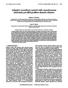
Equation (6) indicates that the correlation function based on a noisy LS channel estimate consists of the ideal CCs in addition to a noise bias [13]. This effect can be seen in the simulated correlation function of Fig. 3. Since the AWGN is random and uncorrelated (i.e., the correlation between the AWGN components at different subcarriers is zero), the term E [Z(k) Z ∗ (k + ∆k )] simplifies to 0 when ∆k 6= 0. However, when ∆k = 0, the term E [Z(k) Z ∗ (k + ∆k )] becomes an autocorrelation which gives the channel estimation error variance. As shown in Fig. 3(a), the correlator removes the bias introduced by the noise at all other lags except the zero lag because Z(k) and Z(k + ∆k ) are uncorrelated when ∆k 6= 0. However, normalising the estimated (and unbiased) CCs w.r.t. the biased zero lag biases the correlation function as in Fig. 3(b). Since the CCs at all other lags except the zero lag do not suffer from a noise bias, they can be used to predict the zero lag CC by means of polynomial fitting. This approach has been proposed in [14] to remove the AWGN effect from a time domain covariance-based velocity estimator, and a similar method has been adopted in [13]. Based on the CCs at all other lags except the zero lag, a polynomial can be formulated as: p X y(∆k ) ≈ ai (∆k + b)i (7)
0.2
0.05
where Z(k) = is the channel estimation error due to the e AWGN. Replacing H(k) in (1) with H(k) in (4) gives the CCs based on real i.e., noisy, channel estimates.
∗
0.25
Noisy LS channel estimate Perfect channel knowledge 200
400
600
Correlation lag
800
(b) Normalised correlation function Fig. 3. Noise effects on the correlation function. signal-to-noise ratio = 3 dB
and the normalised CCs can be obtained by: ˆ H (∆k ) = RHe (∆k ) R p P ai
(9)
i=0
The model presented so far investigates and eliminates the channel estimation errors from the correlation function. However, channel estimation is performed at pilot subcarriers only and an interpolator is needed to estimate the channel at data subcarriers. Thus, (9) can be affected by interpolation errors especially at low pilot densities (i.e., large spacing between the pilots). To overcome this problem, we propose using one of the radio frame1 symbols as a training symbol for all the users to obtain their correlation functions. This eliminates the need for a FD interpolator at the training symbol, hence the FD CCs will not be affected by any interpolation errors. B. Training symbol validation Assuming that the delay spread experienced by each user is fixed over the duration of one radio frame but may change from a radio frame to another, different users at different subframes can obtain the FD CCs based on the estimated CFR at the same training symbol. Then, the result can be used as an indicator for the correlation function at each user’s subframe. This assumption can be validated by considering the 1
Aggregate of several subframes. Unless otherwise stated, the terms radio frame, subframe, resource grid, resource block and resource element have the same definitions as in LTE parlance.
separation property of wireless channels. Given the baseband representation of the channel impulse response (CIR): X h(t, τ ) = γl (t)δ(t − τl ) (10)
Frequency domain
Frequency training symbol
...
l
Example allocations of adaptive pilots
...
where γl is the gain of the l path which is modelled as a wide-sense stationary (WSS) narrowband complex Gaussian process with an average power σl 2 , and τl is the corresponding delay. The sampled Fourier transform of (10) gives the CFR at the nth OFDM symbol and the k th subcarrier H[n, k]. X H[n, k] = γl (nT ) e−j2πkl/K (11)
...
...
th
Example allocations of data resources
...
Time domain training subcarrier
...
subframe #1
subframe #2
subframe #m Time
l
where T is the OFDM symbol duration and K is the total number of subcarriers. As shown in [15], the time-frequency correlation function of the CFR rH (∆n , ∆k ) can be decoupled into a multiplication of a time correlation rH (∆n ) and a frequency correlation rH (∆k ), i.e., 2 rH (∆n , ∆k ) = σH rH (∆n ) rH (∆k )
(12)
with rH (∆n ) = J0 (2 π fd T ∆n ) (13) 2 X σ −j 2 π ∆k l/K l (14) rH (∆k ) = 2 e σH l P 2 = l σl2 = 1 is the total average power of the where σH normalised CIR, J0 is the zeroth order Bessel function of the first kind. The reader is referred to [15] for the derivation of these equations. It can be noticed that (14) does not depend on the symbol index (n) or the time separation (∆n ). Thus for each user, all OFDM symbols of the radio frame have the same FD correlation function regardless of the time variations. This validates the approach of using one training symbol to obtain the FD CCs irrespective of the user’s allocations within the radio frame. From an overhead perspective, the training symbol has a negligible impact because it consumes one OFDM symbol only across the whole radio frame. For example, considering a typical LTE radio frame with 10 subframes each one consisting of 14 OFDM symbols, the training symbol overhead is 0.7%. In addition, the training symbol can be the same symbol used for synchronisation or it can be used as a pilot for the users allocated to the subframe where this symbol is transmitted. In the latter case, the training does not require dedicated resources and hence it does not introduce an additional overhead. Using the normalised CCs obtained by (9), each Rx determines the maximum allowed frequency spacing between the ef ) for a certain FD correlation value (Υf ) as: pilots (N ef = N
max
ˆ H (∆k )≥Υf R
∆k
(15)
For an ideal exponential power delay profile (PDP), the theoretical FD pilot spacing can be formulated as [16]: r� � 2 1 −1 Υf Nf = (16) 2 π στ δf
Fig. 4. Example allocations of a resource grid with adaptive pilot pattern
where στ is the rms delay spread and δf is the subcarrier spacing. Equation (16) is included herein as a reference for evaluations only. C. Adaptive time domain pilot pattern Following a similar approach, the pilot pattern in the TD can be adaptively adjusted according to the TD CCs. The latter is affected by the Doppler frequency which itself depends on the user’s speed. For an accurate estimation of the TD CCs, one subcarrier across the entire time/frequency resource grid will be used as a training subcarrier. By exploiting the separation property, the TD CCs based on the training subcarrier can be used for all other subcarriers irrespective of the frequency variations. Thus all the UEs can obtain their TD CCs by using one subcarrier only which introduces a marginal overhead. In a LTE system with 20 MHz bandwidth, using one of the 1200 subcarriers for the training purpose results into 0.08% overhead. et ) The maximum allowed time spacing between the pilots (N for a certain TD correlation value (Υt ) can be formulated as: et = N
max
ˆ H (∆n )≥Υt R
∆n
(17)
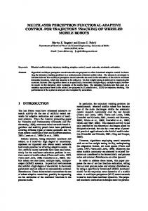
ˆ H (∆n ) is the normalised TD CCs which can be where R ˆ H (∆k ). Fig. 4 shows example calculated in a similar way as R allocations of a resource grid with the proposed adaptive pattern. Notice that the pilot allocations can be uniform across the entire resource grid (i.e., according to the worst-case conditions among the active UEs), or each active UE can have a tailored pilot pattern as shown in Fig. 4. However, the latter case may require a coordination between neighbouring DBSs and/or between antenna ports of the same DBS to avoid a pilot interference. It is worth mentioning that under good channel conditions ef or N et e.g., very small delay spread or very low speed, N respectively can result into a very low pilot density, e.g., one pilot. In this case, the estimated channel at this pilot reflects the stationery channel at the data resources. However the equalised data symbols could be subject to a noise depending on the used estimator and equaliser. This suggests restricting a minimum pilot density in the FD and the TD for noise averaging. In addition, the worst-case distribution can be adopted to initially
NMSE of estimated FD pilot spacing
0
10
−1
10
−2
10
0
Perfect channel knowledge Noisy channel estimate with noise−compensation at zero lag Noisy channel estimate
2
4
6
8
10
12
14
Signal−to−noise ratio [dB]
16
18
20
Fig. 5. NMSE of the estimated pilot spacing with στ = 500 ns
acquire the channel state information before determining the best pilot distribution, e.g., when the UE changes the DBS. IV. S IMULATION R ESULTS Link level simulations have been performed to assess performance and potential overhead savings of the proposed adaptive mechanism. First, the accuracy of the correlationbased pilot pattern estimation is compared with the theoretical spacing of an exponential PDP. The comparison is based on the normalised mean square error (NMSE) given by (18) and the results are reported in Fig. 5. �� �2 � ef E Nf − N NMSE =
h i 2 E (Nf )
(18)
As shown in Fig. 5, the adaptive scheme estimates the required spacing between the pilots with NMSE ≈ 4%, which is roughly the same NMSE of an ideal scenario where the Rx has a perfect channel knowledge. In addition, the proposed method is almost insensitive to the noise level, i.e., it can compensate the noise bias at the zero lag perfectly, hence it performs in low SNR conditions as good as in high SNR ranges. In other words, the adaptive scheme provides a reliable estimation of the required pilot spacing irrespective of the AWGN level. In order to assess potential gains of the proposed mechanism, the theoretical overhead of the adaptive pattern is compared with pilot pattern of the wors-case: 500 km/hr speed and 991 ns rms delay spread. As can be seen in Fig. 6, the adaptive scheme could reduce the pilot overhead significantly. For example, considering a typical local area scenario with στ = 100 ns [9] and 30 km/hr speed, the proposed scheme could reduce the pilot overhead by more than 90% w.r.t. the static/worst-case dimensioned pattern. As expected, the potential gains (i.e., in terms of overhead saving) decrease as the speed and/or the delay spread increase. A second set of simulations is performed to determine performance penalty of the adaptive scheme. A typical LTE CRS pattern for one antenna port [17] is considered as the static/worst-case dimensioned pattern. For simplicity, a full buffer traffic model and a single modulation/coding scheme
Fig. 6. Overhead reduction in the proposed scheme w.r.t. the static worstcase pattern. Simulation parameters: exponential PDP, Υf = Υt = 90%, FFT size = 2048, used subcarriers = 1200, OFDM symbols = 140, minimum pilot density = 2
TABLE I S IMULATION PARAMETERS Parameter
Value
Modulation
QPSK
Coding
Turbo
Estimator
Least square
Interpolator
Linear
Equaliser
Zero forcing
FFT size
2048
Used subcarriers
1200
Subcarrier spacing
15 kHz
Cyclic prefix
Normal LTE cyclic prefix
Channel model
Extended Pedestrian-A (EPA)
Doppler shift
5 Hz
Total bandwidth
20 MHz
Guard band
10%
are adopted. The developed simulator assumes that the users are multiplexed in a time division scheme. In LTE terminology, this means that different users do not share the same subframe, i.e., all resource block pairs of a given subframe are allocated to a single user only. Thus the adaptive FD pilot pattern expands the whole range of used subcarriers while the adaptive TD pilot pattern is bounded by the subframe duration. The minimum pilot density in the FD and the TD is set to two and other simulation parameters are provided in Table I. Fig. 7 compares the bit error rate (BER) of the adaptive scheme with the LTE CRS pattern while Fig. 8 shows the average pilot overhead reduction in the considered simulation scenario. The training resources overhead (i.e., 0.7% for the FD training symbol and 0.08% for the TD training subcarrier) is accounted for whilst calculating the overhead of the adaptive system. It can be noticed that the adaptive pattern provides roughly the same BER performance as the LTE CRS pattern with a slight degradation at high SNR values. As can be seen in Fig. 7, increasing the correlation value improves the performance because high correlation targets require a small spacing between the pilots. With a 95% correlation target for the
0
10
developed model considers both the frequency and the time variations and allows controlling the overhead-performance trade-off by adjusting the required correlation target. The basic concept can be extended to the cyclic prefix and other signals in order to minimise the overall PL signalling.
−1
Bit Error Rate
10
−2
10
−3
10
−4
10
−10
ACKNOWLEDGEMENT
LTE CRS pattern adaptive pattern−95% correlation adaptive pattern−92% correlation adaptive pattern−90% correlation −5
0
5
Signal−to−noise ratio [dB]
10
15
Fig. 7. BER of the proposed adaptive pattern vs LTE CRS pattern
This work was made possible by NPRP grant No. 5-10472437 from the Qatar National Research Fund (a member of The Qatar Foundation). The statements made herein are solely the responsibility of the authors. We would like to acknowledge the support of the University of Surrey 5GIC members for this work.
Overhead reduction w.r.t. LTE CRS %
R EFERENCES 100 80 60 40 20 0
adaptive−95% correlation adaptive−92% correlation adaptive−90% correlation
Fig. 8. Overhead reduction in the proposed scheme w.r.t. LTE CRS pattern
adaptive scheme, the performance is almost the same as the worst-case pattern for SNR values less than 10 dB. However at SNR ≥ 10 dB, the adaptive pattern degrades the performance by 0.7−1.6 dB. This can be traced to the fact that noise effects are marginal in the high SNR range, hence the interpolation errors dominate. Since the proposed scheme adapts the pilot spacing according to the channel variations, the pilot interval would be larger in the adaptive system as compared with the worst-case dimensioned system. Thus, at high SNR, the interpolation errors have a higher impact on the performance of the adaptive pattern. Nonetheless, using robust interpolation techniques such as low pass or spline interpolators [18] could eliminate this difference. Compared with the LTE CRS pattern, Fig. 8 indicates that the proposed mechanism reduces the pilot overhead by 74−78% in the considered simulation scenario. In addition, the overhead saving increases as the correlation target decreases. Expressed differently, there is a trade-off between the performance and the overhead that can be controlled by the FD and the TD correlation values, i.e., Υf and Υt respectively. V. C ONCLUSION In the CDSA, the feature of the DBS as a serving node for active UEs only lends the DBS-UE link to flexible operations and dynamic allocations rather than adopting the worst-case design approach. In this direction, the proposed correlationbased adaptive pilot scheme can significantly reduce the overhead without a significant performance degradation. The
[1] J. G. Andrews et al., “What will 5G be ,” IEEE J. Sel. Areas Commun., vol. 32, no. 6, pp. 1065–1082, June 2014. [2] F. Khan, LTE for 4G mobile broadband: air interface technologies and performance. Cambridge University Press, 2009. [3] S. Sesia, I. Toufik, and M. Baker, LTE: the UMTS long term evolution. Wiley Online Library, 2009. [4] A. Mohamed, O. Onireti, Y. Qi, A. Imran, M. Imran, and R. Tafazolli, “Physical layer frame in signalling-data separation architecture: Overhead and performance evaluation,” in Proc. of 20th European Wireless Conference, May 2014, pp. 820–825. [5] C. Hoymann, D. Larsson, H. Koorapaty, and J.-F. Cheng, “A lean carrier for LTE,” IEEE Commun. Mag., vol. 51, no. 2, pp. 74–80, February 2013. [6] H. Ishii, Y. Kishiyama, and H. Takahashi, “A novel architecture for LTEB :C-plane/U-plane split and phantom cell concept,” in Proc. of IEEE Globecom Workshops, December 2012, pp. 624–630. [7] X. Xu, G. He, S. Zhang, Y. Chen, and S. Xu, “On functionality separation for green mobile networks: concept study over LTE,” IEEE Commun. Mag., vol. 51, no. 5, pp. 82–90, May 2013. [8] T. Nakamura et al., “Trends in small cell enhancements in LTE advanced,” IEEE Commun. Mag., vol. 51, no. 2, pp. 98–105, February 2013. [9] E. Laehetkangas et al., “On the selection of guard period and cyclic prefix for beyond 4G TDD radio access network,” in Proc. of 19th European Wireless Conference, April 2013. [10] R. Negi and J. Cioffi, “Pilot tone selection for channel estimation in a mobile OFDM system,” IEEE Trans. Consum. Electron., vol. 44, no. 3, pp. 1122–1128, August 1998. [11] J.-J. van de Beek, O. Edfors, M. Sandell, S. Wilson, and P. Ola Borjesson, “On channel estimation in OFDM systems,” in Proc. of IEEE Vehicular Technology Conference, vol. 2, July 1995, pp. 815–819. [12] H. Yin, D. Gesbert, M. Filippou, and Y. Liu, “A coordinated approach to channel estimation in large-scale multiple-antenna systems,” IEEE J. Sel. Areas Commun., vol. 31, no. 2, pp. 264–273, February 2013. [13] T. Yucek and H. Arslan, “Delay spread and time dispersion estimation for adaptive OFDM systems,” in Proc. of IEEE Wireless Communications and Networking Conference, vol. 3, April 2006, pp. 1433–1438. [14] C. Tepedelenlioglu and G. Giannakis, “On velocity estimation and correlation properties of narrow-band mobile communication channels,” IEEE Trans. Veh. Technol., vol. 50, no. 4, pp. 1039–1052, July 2001. [15] Y. Li, L. Cimini, and N. Sollenberger, “Robust channel estimation for OFDM systems with rapid dispersive fading channels,” IEEE Trans. Commun., vol. 46, no. 7, pp. 902–915, July 1998. [16] S. Saunders and A. Arag´on-Zavala, Antennas and propagation for wireless communication systems. John Wiley & Sons, 2007. [17] ETSI, “Evolved universal terrestrial radio access (E-UTRA); Physical channels and modulation,” Tech. Spec., January 2014, 3GPP TS 36.211 version 11.5.0 Release 11. [Online]. Available: http://www.etsi.org/deliver/etsi ts/136200 136299/136211/ 11.05.00 60/ts 136211v110500p.pdf [18] S. Coleri, M. Ergen, A. Puri, and A. Bahai, “Channel estimation techniques based on pilot arrangement in OFDM systems,” IEEE Trans. Broadcast., vol. 48, no. 3, pp. 223–229, September 2002.