robotic arm is controlled with built in circuitry or using a computer connected ... Keyword : - Arduino, Servo Motor , Potentiometer, and arm. 1. ... Actually, manual.
Vol-4 Issue-4 2018
IJARIIE-ISSN(O)-2395-4396
Cost Efficient and Fail-Safe Robotic Arm and Control System Liton Mazumder1, Prof Farruk Ahmed 2 1 2
Student, Department of Computer Science and engineering, Independent University, Bangladesh Professor, Department of Computer Science and engineering, Independent University, Bangladesh
ABSTRACT The main objective of this project work is designing and implementing a robotic hand which can help us to accomplish simple tasks such as carrying light-weight materials, serving as a helping hand for industrial workforces etc. The arm is equipped with servo motors to perform arm movements. Through the entire project analysis, the robotic arm is controlled with built in circuitry or using a computer connected joystick device. The arm consists of base, upper-arm, fore-arm and gripper. The robot is capable of 3 degrees of freedom. The development of this arm is based on Arduino Uno platform. The analysis such as speed, distance and load taking capacity of the robotic arm has been done in order to measure its performance. In our tests it worked properly for small and light material handling. We made it easily reprogrammable to serve different purposes on demand using a GUI based Command Center that can keep multiple commands saved in it. Upon invoking the Command Center would cycle through the command one after another essentially automating the repetitive work by the robotic arm. We kept the cost of building the robot sufficiently low and easily portable and installable in different places according to user’s needs.
Keyword : - Arduino, Servo Motor , Potentiometer, and arm 1. Introduction Today the use of robots besides humans is increasing dramatically. In many cases, robot is replacing humans in the tasks that are highly repetitive or unsafe for humans. Our goal in this project was to design and develop a low cost ultra-chip robotic arm. This system will be controlled by user inputs. It can be used for industrial works for light material handling or direct different objects in conveyer line. It can also be used in device block picking, home automation system etc. Portable robots are currently used in many sectors of applications including office, military tasks, dangerous environment and agriculture. Besides, it might be difficulties to the worker whose must pick and place something that can endanger human life. For example, things like defusing a bomb is very dangerous for humans and needed a robot to pick and place the bomb to somewhere. In that case, a locomotion robot can be used to replace human.
2. Algorithm for the Arm to 2.1 APPROACH
Work and Implementation
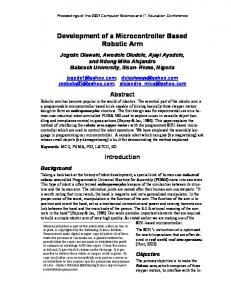
A. Mechanical Design The functionality of robotic arm is similar to a human arm. For instance, our arm has three joints and two limbs so that it will get 3 degrees of freedom and it can at least grab and lift small block pieces. In Figure 1 we can see the mechanical design of the robotic arm.
9034
www.ijariie.com
1269
Vol-4 Issue-4 2018
IJARIIE-ISSN(O)-2395-4396
Figure -1: Mechanical Design of the robotic arm The robot arm joints are typically actuated by electrical servo motors. This servo motors were chosen because they include encoders which automatically provide feedback to the motors and adjust the positions accordingly. The mechanical design is limited to 3 degrees of freedom because that successfully works as our need and lows most of the necessary movement costs. B. Mathematical Modeling The base joint of the robotic arm has a rotation is θr= 180o, the rotation of second joint is θs = 180o and the rotation of third joint is θt = 180ofirst limb produces an angle of θb = 90owith the base, second limb produces θc = 0o angle with the first limb, third limb produces θd = 0oangle with the second limb. We can express this with matrix:
We are using three Potentiometers to control the three limbs so we will get the control data’s from its inputs. We placed the three 10K potentiometers and three 1K resistance in parallel connection. So when the voltage of potentiometers increases then the rotation of corresponding motors also increases also increases. For first limb the angle increases from 90o Θb= 90 + 5*9 = 135o [Range 90o to 135o] For the second limb the angle increase from 0o with respect to first limb Θc = 0+6*10 = 60o [Range 0o to 90o] For the third limb the angle increase from 0 o with respect to second limb Θd = 0 + 5*9 = 50o [Range 0o to 45o] 2.2 Algorithm for the Arm to Work and Implementation We used a number of potentiometers that are connected with the Arduino and it will interpret the values and then send a command to the servo motors. Then the servo motors will work accordingly. The following flowchart shows the workflows of the algorithm:
9034
www.ijariie.com
1270
Vol-4 Issue-4 2018
IJARIIE-ISSN(O)-2395-4396
At first, we set the angle for the first limb to 90 o, the second limb will be at 0o with respect to first arm and the third limb will be at 0o with respect to second arm. Then we will rotate the first potentiometer to rotate the first limb. We need to rotate the second potentiometer to adjust its angle with respect to the first limb. Similarly, we need to rotate the third potentiometer to adjust its angle with respect to the second limb. The arduino interprets the signals and for the first potentiometer it rotates the first limb, similarly it rotates the second limb by interpreting the signal of the second potentiometer. Same case happens for the third limb
Chart -2: Flowchart of the algorithm.
3. EXPERIMENT AND FIELD TEST-3 We use limbs of various lengths to efficiently lift weights. The first limbs length is , the second limbs length is and the third ones length is . The first base joint can handle 0.8kg and second joint also can handle 0.8kg. The first limb can give 0.8kg torque to the second limb and the second limb can give 0.6 kg torque approximately because the momentum changes due to length to the third limb which is sufficient to lift Light weight objects. We try to use manual controlling on our robotic arm. This type of control is useful in specific positions. In case of mandatory positions that the motors cannot calculate their valid angles, we may use the manual control. Actually, manual control has a series of analog inputs, such as potentiometers, that are connected with the Arduino and it will interpret the values and then send a command to the servo driver. Possible implementation includes feature where the Arduino stores positions in memory and by a keypad or a series of switches we may recall these positions.
4. TESTING AND VALIDATION We did a number of tests to validate the robotic arm and its elements. We tested the by sending different commands by the Arduino software to Arduino circuit and check changes on the outputs that are connected to the servo motors which are responsible for turning on or off depending on the command.
9034
www.ijariie.com
1271
Vol-4 Issue-4 2018
IJARIIE-ISSN(O)-2395-4396
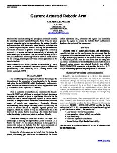
To each servomotor we send different direct pulses and then we verify if it rotates correctly or not. We used a mark to know where the initial position was and the final position of the motors is determined by sending a signal with the Arduino and, in turn, servo interpreted it and compared to the signal provided by the encoder, resulting in the rotation to the desired position. Other tests were performed to verify the functionality of the whole system, as shown in Figure 03.
Fig -3: Robotic arm in action.
5. RESULTS AND ANALYSIS During testing one of our motors got burnt because the measurement was not right for some arm portions and it created extra pressure on the motor by putting extra weight. Other than this we had problem with grippers to work properly. We tried to fix everything an now its working. The arm has managed to pick lightweight small block pieces.
6. FUTURE WORKS Our future target is to spread this arm in places where this type of robot is applicable. We also want to make it really cheap. For the manufacturer, Industrial robotic arm has many advantages. If we integrate a robotic arm into a production line, the production speed will increase because the robot will reduce the cycle time between each work piece. The quality of the product also begins to progress due to the robot’s ability to accurately polish edges, produce straighter welds or drill précised holes. This just improves the product over time continually, while improving the integrity of the brand also. Industrial robotic arms also decrease injuries and accidents that happen during the working. With these robots, workers are kept clear of risky environments, poisonous fumes and sometimes tedious and injury-inducing work. These same workers also gain a new skill set when learning how to program these user-friendly industrial robotic arms.
7. CONCLUSION Robots help people with tasks that would be difficult, unsafe, or boring for a real person to do alone. Thus this project can also help as an assistant for a physically challenged person. To conclude, robotic arm is gives us hope to make a full-fledged robot in future in our country.
ACKNOWLEDGMENT We are really grateful to Independent University, Bangladesh (IUB) for their logistic and technical support. We want to thank all who have been directly related to this thesis for their support.
9034
www.ijariie.com
1272
Vol-4 Issue-4 2018
IJARIIE-ISSN(O)-2395-4396
REFERENCES [1]. AshrafElfasakhany and Karen Baylon, “Design and Development of a with Four Degrees of Freedom”,DOI, 2011.
Competitive Low-Cost Robot Arm
[2]. Berceanu Cosmin and Tarnita Daniela, “Rapid Prototyping And Embedded Control For An Anthropomorphic Robotic Hand”, COMEC, 2009 [3]. Deepak Tolani, Ambarish Goswami, and Norman I. Badler, “Real-Time Inverse Kinematics Techniques for Anthropomorphic Limbs”, DOI, 2000. [4]. Google.com for primary help. [5]. Wikipedia for other technical help.
BIOGRAPHIES & PHOTOGRAPHS Liton Mazumder (Assistant Researcher School of Engineering and computer Science at Independent University of Bangladesh)
Farruk Ahmed (Prof School of Engineering and computer Science, Independent University of Bangladesh)
9034
www.ijariie.com
1273