preparing Emergency Medical Service personnel prior to their arrival at the .....
1302 1994. Chevrolet ... X. 1109 1993. Plymouth. Voyager van. Collinear rear
impact of the stationary. Voyager by a ..... of Body Data (GEBOD) Manual,” Report
no.
CRASH VISUALIZATION USING REAL-WORLD ACCELERATION DATA Robert A. Galganski Bruce R. Donnelly Alan Blatt Center for Transportation Injury Research Louis V. Lombardo U.S. Department of Transportation/National Highway Traffic Safety Administration USA Paper Number 357
ABSTRACT Vehicle crash-event data recorders associated with inflatable occupant restraint systems, Mayday systems, and Automatic Crash Notification systems are rapidly becoming more common and more sophisticated. If such devices are equipped with integral accelerometers, it is possible to input the actual vehicle accelerationtime history recorded during the crash to a suitable occupant dynamics computer analysis to simulate near real-time in-cabin occupant response to the roadway incident. This paper describes how the Articulated Total Body computer code was utilized for this purpose. Real-world acceleration-data inputs to the code were obtained from the Automatic Crash Notification Field Operational Test program recently completed by Veridian Engineering for the U.S. Department of Transportation/National Highway Traffic Safety Administration. The simulations provided animated video imagery depicting virtualoccupant motion and secondary impacts in the cabin for several collisions selected from that program. Preliminary indications are that such forecasted visual information would have potential value in activities such as planning ground and air ambulance transport, preparing Emergency Medical Service personnel prior to their arrival at the crash scene, aiding destination decisions, and alerting emergency medical personnel regarding injury type and severity. INTRODUCTION This paper outlines how actual motor-vehicle acceleration data from several real-world collisions was used in conjunction with the Articulated Total Body computer analysis to generate animated images of simulated occupant motion inside the vehicle cabin. The authors posit that the insights gleaned from such video clips would help emergency rescue and medical personnel anticipate the types of injuries that might have occurred at the crash scene—before the victims arrive at an emergency room or trauma centerand
thus support crash-victim triage and treatment decisions. BACKGROUND Veridian Engineering recently completed field operational testing of an advanced Automatic Crash Notification (ACN) system it had designed and constructed for the U.S. Department of Transportation, National Highway Traffic Safety Administration (NHTSA). A total of in 874 vehicles operating on the roads of western New York State were equipped with an in-vehicle module (IVM), a three-watt cellular phone package, and two antennas. The IVM includes a Global Positioning System (GPS) unit, three orthogonal floorpan-mounted accelerometers (to record the vehicle’s linear crash-pulse components), a digital signal processor, a modem, and flash memory. When the IVM detects a crash incident, it opens a hands-free voice phone line between the vehicle and a 9-1-1 emergency-message center and transmits to the center a record of the vehicle location, crash pulse, velocity change, and final rest position. It also indicates the principal direction of crash force. Twenty-two of the above-noted vehicles were involved in an impact that exceeded the prescribed program crash-notification threshold; fifteen of these were subjected to a full investigation. Experienced Veridian Engineering personnel examined each vehicle, interviewed witnesses and vehicle occupants, estimated the crash forces, reconstructed the crash events, and obtained medical records for all injured occupants. Injuries were identified and categorized consistent with the Abbreviated Injury Scale (AIS) classification. The study described in this paper utilized the recorded vehicle crash pulse and the corresponding calculated initial impact speed from a selected number of ACNprogram collisions as input to occupant/cabin-interior mathematical models developed with the ATB code.
Galganski, 1
THE CRASH VISUALIZATION CONCEPT This section discusses crash visualization in a generic sense, with emphasis on its needs and the inherent complicating issues that must be addressed. Requirements Crash visualization utilizes a computer code that can generate and display, with reasonable accuracy, vehicle-occupant kinematics in a simulated crash environment. For trauma-triage applications, it is imperative that the animated images be available for viewing as quickly as possible, preferably in five minutes or less. The code would be used to develop a comprehensive library of validated, ready-to-run mathematical models of the vehicle cabin and its occupants. They would be configured for use with typical roadway crash modes and incorporate representative cabin-interior designs, occupant seating positions, occupant/restraint-system configurations, and a number of variants. An acceptable number of virtual occupant types would be available to simulate an appropriate human-population mix. Ideally, the models should be capable of handling occupants in both standard and off-design positions and postures and accommodate varied restraint-system positioning and inflation conditions. A reliable set of inputs to the model is also required. They include cabin geometry and cabin-interior surface force-deflection and energy absorption characteristics; occupant position, posture, and orientation on the seat; belt restraint-system physical properties, geometry, and positioning relative to the occupant; spatial relationships between the various surfaces in the cabin as well as between the occupants themselves, the surrounding volume, and restraint system(s); and the vehicle-cabin crash signature and initial impact speed. Complicating Issues Mathematical modeling of any physical system is an inexact process; the model provides a best-guess estimate of what really happens in the real world. The analysis itself used to formulate the model of the system constitutes an approximation that takes into account manybut usually not allof the variables that govern the physical process(es) and events being examined. The dynamic response of an occupant inside the cabin of a vehicle undergoing a crash exemplifies just such an extremely complex series of interrelated events.
Currently, even the most sophisticated occupant dynamics codes cannot guarantee absolute fidelity between computer-generated dummy-response results and their corresponding equivalents obtained via experimental testing, where initial conditions are reasonably well controlled. It is expected that occupant simulations of real-world roadway crashes would exhibit even greater disparities between actual and virtual occupant kinematics because of the numerous uncertainties present at the crash scene. In addition to those alluded to earlier, factors such as occupant anthropometry, age, strength, and possible defensive posture (e.g., bracing against a perceived impending collision) are not accounted for by extant computer codes. It is anticipated, however, that such incertitude will decrease in the not-too-distant future as vehicle manufacturers incorporate computerchip and other state-of-the-art technology into their products in response to market incentives. INITIAL CODE SELECTION: ATB The Articulated Total Body code (ATB) [1] was employed in this initial feasibility study of the crash visualization concept. ATB is a widely used generalpurpose three-dimensional lumped-mass analysis that can be used to simulate the response of virtually any object in a dynamic environment. Originally developed as CVS (Crash Victim Simulation) [2] more than two decades ago for NHTSA by Veridian Engineering (the former Calspan Corporation), it has undergone numerous revisions over the years and continues to be upgraded for both general and specific applications. ATB idealizes the human body as an articulated assembly of point-mass segments, each surrounded by an ellipsoidal surface that provides shape and inertial properties. These segments are connected and constrained by appropriate joints having rotationresistive torques and motion stops. A companion computer program called GEBOD (Generator of Body Data) [3] supplies ellipsoid and joint data for a wide variety of user-specified crash-test dummies and humans. ATB provides, from any perspective inside or outside the cabin, a computer animation showing occupant motion, occupant interaction with restraint system components, and any impacts that may occur between an occupant and cabin interior surfaces or other occupants. Time histories of the accelerations and forces sustained by all occupant body regions during the crash are also generated.
Galganski, 2
Myriad other tabular information is also provided, including body-segment joint angles and torques, the location of occupant/cabin interior contacts, and the values of selected injury-indicating parameters such as the Head Injury Criterion (HIC) and its associated computational interval. Plots of virtually all output parameters are easily generated. ATB was selected because it is a cost efficient analytical tool that satisfied the requirements of this project. Like all currently extant occupant dynamics codes, ATB does have its shortcomings. If ATB is to be considered a viable candidate for use in possible future work in this endeavor, they will have to be addressed. A detailed overview of these deficiencies is included in James et al. [4] How some of them specifically affected the simulations made in this study is discussed in a later section. MODEL FORMULATION In any mathematical modeling application, it is imperative that the required level of modeling detail needed to capture the salient features of the physical process being simulated be identified. This section outlines the methodology followed to develop the models employed in this study. Cabin Geometry and Degree of Modeling Detail All simulations used a cabin configuration basically reflecting the overall dimensions and interior layout of a small sport-utility vehicle (SUV). Flat planes representing actual cabin-interior surfaces were defined to document occupant secondary impacts, monitor close occupant approaches with those surfaces, and provide a complete cabin shell for graphical purposes. It was not clear at the outset how closely the cabininterior model had to match its actual counterpart. Code limitations in the form of a maximum number of planes and a maximum number of allowable contacts between body ellipsoids and these planes, however, precluded modeling the cabin to any great degree of detail. The general philosophy followed therefore was to use only a small number of planes, adding planes and specifying potential contacts only when required. At the time the simulations were performed the maximum number of planes and the allowable number of ellipsoid/plane contacts were restricted to 50 and 200, respectively. (These parameters have doubled in the latest version of the code, 1.3.00.) The first simulation utilized single-plane representations of a bench-type seat back and fullwidth bucket seat cushions separated by a console.
This Spartan design was selected in an effort to conserve planes for possible use elsewhere in the cabin if the need arose. Subsequent simulations required the use of additional planes in order to prevent certain body ellipsoids from “slicing” through parts of the interior during the crash. And in a later run the seat cushion and back were split into two parts to permit individual adjustment of the seat location in the cabin. It was assumed that all planes did not deform or shift during the simulation. Possible cabin intrusion and displacement of the steering wheel were thus not accounted for. With one possible exception, such action did not appear to be a major factor in the crashes modeled. (ATB can simulate intrusion by allowing a plane or previously stationary ellipsoid to move, but the user must prescribe its displacement as a function of time.) Cabin Surface and Restraint-Belt Force-Deflection Characteristics Force-deflection properties specified for the cabin planes were identical to those utilized in an extensive series of occupant simulations performed earlier by Veridian for a major light-truck manufacturer. Some of that data had been obtained from component-level experimental testing while others were generated via trial and error. The latter relationships had provided satisfactory results in that program. Belt-restraint properties employed also came from the above-noted program. The data were generated via experimental testing of production belt webbing. Occupant Setup Fifteen body segments were used to represent the occupants: head; neck; upper, middle, and lower torsos; upper and lower legs; feet; and upper and lower arms. The hands were considered part of the lower arms. It was often necessary to utilize additional “auxiliary” ellipsoids to bridge the “valley” between two adjoining primary ellipsoids (e.g., the intersection of the lower torso and the center torso) and thus prevent a restraint belt (in this example, the lap portion) from “slicing” through that area. Occupants were all placed in a standard seated position: shoulders parallel to the seat back, facing straight ahead. A single friction coefficient successfully employed in the aforementioned lighttruck effort was used for all ellipsoid/surface contact conditions.
Galganski, 3
As per standard ATB practice, all possible occupant contacts envisioned were specified a priori. (Failure to do so permits an occupant ellipsoid to “pass through” a plane or another ellipsoid as if it wasn’t really there.) Fixed restraint-belt anchorage locations matched those employed in the selected SUV. The lap belt was positioned so that it engaged the lower-torso and upperleg segments while the shoulder belt was initially positioned to contact the lower-, middle-, and uppertorso segments. In some cases additional contacts between the belts and other ellipsoids (e.g., the shoulder belt and the neck and head ellipsoids) were specified to prevent a belt from passing through that body region during the simulation. RUN-EXECUTION AND ANALYSIS PROTOCOLS In an effort to preclude biasing model setup, the analyst was not given access to the complete information packageincluding occupant injuriescompiled for a given ACN crash until the simulation was completed. Prior to that time, he was provided only the minimum information needed to set up and run the model: vehicle and occupant descriptions, seating positions, and vehicle crash-pulse data and initial impact speed. As a consequence of the above-noted restriction, certain inputs remained constant for each crash simulation. No attempt was made to “tune” or optimize parameters to obtain better correlation between “predicted” results and actual occupant injuries. In some cases, however, it was necessary to alter the location of the B-pillar belt anchor point and passenger bucket seat because of occupant size considerations. For each case considered the analyst prescribed, a priori, a preliminary set of allowed contacts between relevant combinations of body ellipsoids and the surrounding cabin planes. The model was then exercised in an initial test run and the animation studied to ascertain the resulting virtual occupant motion and secondary impacts in the cabin. If an ellipsoid passed through a plane or another ellipsoid, additional contacts and/or contact planes were specified as needed and another test run made. This process was repeated in an iterative manner until all such interactions and close surface approaches were fully accounted for. Belt interaction with specified body ellipsoids was also closely scrutinized during these preliminary runs and auxiliary ellipsoids added as required.
Proper restraint-belt positioning and ellipsoid-contact considerations played a critical role in setting up the occupant models. In some cases, numerous trial runs were made before what the analyst deemed to be physically plausible and “well behaved” occupant kinematics and restraint-belt action were attained. Obviously it was not possible to validate, per se, the models developed in this study. Consequently, simulated occupant response was regarded to be a good “match” to that expected in the actual crash if two criteria were met: (1) occupant kinematics displayed no counterintuitive actions, and (2) the forecasted bodyregion contacts and near contacts with cabin-interior surfaces couldin at least a gross sensehave produced the injuries sustained by the corresponding ACN-vehicle occupant. In an attempt to compensate for the numerous uncertainties present in the model input, a sufficiently close approach of a body ellipsoid to a cabin-interior surface was regarded as a probable contact. SIMULATION RESULTS AND DISCUSSION Most of the injuries suffered by ACN-vehicle occupants in the 15 crashes that were fully investigated during the program were non-codeblethat is, their severity was below the minimum level defined by the Abbreviated Injury Scale. (Note: The AIS system ranks injuries on a scale from 1 to 6, with 1 being minor, 5 severe, and 6 an unsurvivable injury.) Three crashes produced injuries of a moderate nature (AIS 2 and 3) to one or more occupants. These, plus another crash in which only minor injuries were sustained, were modeled using the ATB code as outlined in the preceding sections. Table 1 provides a summary of the ACN crashes simulated in the order in which they were performed. This section describes the qualitative output generated for the virtual occupants in those runs and correlates it to the actual injuries suffered by their human counterparts. ACN Case 1094 The ACN vehicle (Ford Explorer) was moving at 43.5 mph, about to make a right turn into a store parking lot. Another vehicle (Ford Thunderbird) made a left turn from the opposite lane, striking the Explorer on the left side. The Explorer continued moving forward and yawed somewhat, causing its right-rear wheel to strike a hard snow bank at the edge of an intersection.
Galganski, 4
Table 1. ACN Crash Cases Simulated With The ATB Code
Initial ACNVehicle Impact
ACN-Vehicle Occupant Information
ACN Case
ACNEquipped
No.
Vehicle
1094
1991 Ford Explorer sport-utility vehicle (SUV)
Angled frontal impact with a 1983 Ford Thunderbird (PDOF = 11), followed by right-rear wheel impact with a hard snow bank (PDOF = 2)
43.5
1104
1993 Ford Taurus station wagon
Angled frontal impact with a 1998 Pontiac Sunfire coupe (PDOF = 2)
10
Female, 70, 100 pounds
X
X
1302
1994 Chevrolet Cavalier sedan
Collinear rear impact with a 1997 Dodge van (PDOF = 12)
41.6
Female, 51, 130 pounds
X
X
1109
1993 Plymouth Voyager van
Collinear rear impact of the stationary Voyager by a GMC Jimmy SUV (PDOF = 6), which pushed the Voyager into the rear of a stationary Ford (PDOF = 12)
0
Male, 49, 220 pounds
X
X
X
X
X
Crash Description
Descriptio n
Speed (mph)
Seating Position LF RF
Male, 68, 165 pounds
X
Female, 67, 105 pounds
Female, 17, 108 pounds
Restraint Condition/Action Belt System
Air Bag
X X
X
LF and RF denote the driver and right-front passenger seating positions, respectively. PDOF: Principal direction of impact force.
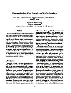
Figure 1 presents a plot of the crash-pulse components recorded at the scene. The Thunderbird and snow-bank impacts generated the highest acceleration-component magnitudes in the y or lateral vehicle direction. The latter impact, which was more severe, actually triggered the automatic collision notification process.
The driver, who was wearing a three-point belt, sustained cervical neck strain, an abrasion on top the head, and complained of pain in his left thigh. The passenger was unrestrainedshe had unbuckled her safety belt in anticipation of the impending stop. She sustained a compressed fracture of the L1 vertebra (AIS 2) and mentioned that her head struck the windshield. (The latter claim is unsubstantiated by the medical report; no visually apparent injury is indicated.)
Galganski, 5
6 X acceleration 4
Z acceleration Y acceleration
2
0
-2
-4
-6
-8 -3
-2
-1
0
1
2
3
4
Time (seconds) Figure 1. Recorded 1991 Ford Explorer Crash Pulse Components From Case 1094. ATB’s animation of the action inside the cabin showed that both occupants initially moved forward and left as a result of the Thunderbird impact, consistent with the physics of the collision. They subsequently moved to the right as a result of the impact with the snow bankagain as expected. An unrestrained vehicle occupant runs the risk of incurring numerous potentially high-speed secondary impacts with cabin-interior surfaces. The animation confirmed that expectation. Figure 2 presents several “snapshots” taken from two different animation views showing the more notable contacts and near contacts experienced by the virtual passenger. (Selected cabin planes were omitted to permit ATB’s “camera” to capture the action inside.) As shown in Figure 2a, the left-upper leg and the lower-torso ellipsoids (the latter the virtual analog to the human hip/buttocks region) are in contact with the console side panel at about 867 milliseconds (ms) into the crash. Shortly afterward (at 900 ms—see Figure 2b), the head ellipsoid nearly strikes the upper dash panel. Figure 2c shows that at 1,256 ms, the occupant has risen from the seat and its
lower-torso ellipsoid has sustained a relatively highspeed (compared to the earlier contact with the console) impact with the right door panel. Finally, the head is seen grazing the windshield surface at 1,378 ms into the incident, confirming what the victim had said (Figure 2d, in which the windshield is depicted as a thin line). The animation also indicated several others near contacts during the crash. It is of interest to examine the passenger’s resultant lower-torso acceleration time history depicted in Figure 3. The first and second peaks correlate with the secondary impacts experienced by this ellipsoid with the console and door panel, respectively. For reasons alluded to earlier, the absolute magnitudes of these estimates should not be construed as the actual maximum accelerations that the equivalent human body regions would have experienced. Rather, they provide a relative indication of impact severity. In this case, the second impact is more severe than the first. From this we can infer that the latter secondary impact with the door panel was the most likely cause of the fractured lumbar.
Galganski, 6
(a) Left-upper leg and lower-torso ellipsoids contact console
(b) Head ellipsoid nearly strikes dash
(c) Lower-torso ellipsoid contacts door panel
(d) Head ellipsoid grazes windshield
Figure 2. Case 1094 Unrestrained Right–Front Passenger Action “Snapshots.” 25.0
20.0
15.0
Impact with right door panel
10.0
Impact with console
5.0
0.0 0
250
500
750
1000
1250
1500
1750
2000
Time (milliseconds)
Figure 3. Case 1094 Right-Front Passenger Resultant Lower-Torso Acceleration Response.
Galganski, 7
Inasmuch as he was restrained, the ACN-vehicle driver sustained injuries that were considerably less severe than those suffered by the passenger. This fact was corroborated by the ATB-generated animation. Figure 4 provides selected instantaneous “stills” of the virtual driver’s kinematics during the crash. The first snapshot of interest here (see Figure 4a) is at 867 ms, where the head and left-upper arm ellipsoids are in contact with the left-side window and left-door panel, respectively. This impact may have caused the head abrasion (AIS 1) incurred by the human driver. The picture at 1,589 ms illustrates an extreme twisting action of the neck and head ellipsoids relative to the upper torso ellipsoid (Figure 4b). This action may have been responsible for the reported cervical strain (AIS 1). Somewhat later (1,856 ms—see Figure 4c), the lower-torso and leftupper leg ellipsoids are in contact with the left-door panel. Perhaps the driver’s upper-thigh pain resulted from this engagement. Finally, the snapshot at 1,878 ms (Figure 4d) suggests that the two occupants in the
actual crash may have come close to colliding during the incident.
(a) Head and left-upper arm ellipsoids contact left-side window and door panel, respectively
(b) Extreme neck and head ellipsoid rotation
(c) Left-upper leg and lower-torso ellipsoids contact left-side door panel
(d) Virtual occupants nearly collide
ACN Case 1104 The ACN vehicle (Ford Taurus sedan) was in an intersection attempting to execute a left turn, moving at about 10 mph. Another vehicle (a van) was in the opposite left lane waiting to turn left. That vehicle prevented the Taurus driver from seeing a 1998 Pontiac Sunfire coupe that passed through the intersection and subsequently collided with the right side of the Taurus. The Taurus driver was wearing a three-point belt. A frontal air bag was available in the vehicle but did not deploy during the crash. The female victim sustained a fractured sternum (AIS 2) and mid-chest contusion (AIS 1). Her age (70) was probably a major causal factor to that skeletal injury.
Figure 4. Case 1094 Belt-Restrained Driver Action “Snapshots.” The animation showed that the virtual occupant moved forward and to the right during the crash, consistent
with physics. The lower-torso and right-upper leg ellipsoids contacted the right side of the console, which
Galganski, 8
in turn led to an upper-body rolling motion and downward slippage of the shoulder belt along the upper-torso ellipsoid. That body region subsequently contacted the left-top edge of the console (see Figure 5). Shortly afterward, the right-upper arm ellipsoid contacted the top of the console and prevented the neck and head ellipsoids from coming in direct contact with that surface.
Figure 6. Case 1302 Driver Maximum Forward Excursion. ACN Case 1109
Figure 5. Case 1104 Driver Contact with the Center Console. Given the real occupant’s age, a reasonable premise is that upper-body interaction with the console similar to that forecasted by the model was responsible for the skeletal injury as well as the contusion. ACN Case 1302 The ACN-equipped vehicle (Chevrolet Cavalier) was moving at 41.6 mph when it struck the rear of a Dodge van, which was stopped in traffic. The Dodge, in turn, rear-ended a Mercury sedan, also stopped in traffic. The Cavalier driver was wearing a three-point belt. The female victim suffered a forehead contusion from impact with the horn pad (AIS 1), pain in the left side of the neck, a chest contusion (AIS 1), a right-knee abrasion from impact with the lower dash panel (AIS 1), and two injuries to the left hand (AIS 1 and 3). In this case, the animation showed that the virtual occupant’s entire body moved forward and pitched, as expected. Both lower-leg ellipsoids engaged the lowerdash panel and the head ellipsoid rotated toward but did not contact the plane of the steering wheel (see Figure 6). The simulation indicated shoulder belt slippage over the upper-torso ellipsoid. This may have been the causal mechanism for the chest contusion suffered by the actual Cavalier occupant during the crash.
This incident involved a pair of collinear collisions. The ACN-equipped vehicle (Plymouth Voyager van) was stopped, waiting in traffic, when it was rear ended by a GMC Jimmy sport-utility vehicle. The impact propelled the Voyager into the back of a stopped vehicle (Ford unnamed model). The Voyager male driver, who was wearing a threepoint belt, sustained a contusion on his right leg below the knee as well as abrasions on the left elbow, right knee, and right calf (all level AIS 1). He also reported cervical strain (AIS 1). A driver-side frontal air bag was available and deployed on the second impact. The female right-front passenger was identically restrained. She reported cervical neck strain only (AIS 1). A passenger-side frontal air bag was available and also deployed on the second impact. ATB was able to model vehicle-occupant response to the first impact only (before the air bags deployed) because the code’s air bag algorithm is not currently functional. The animation correctly showed that both virtual occupants reclined in response to the first impact, with full restraint provided by their respective seat back and head restraint (see Figure 7). A short segment of the shoulder belt remained in contact with the upper-torso ellipsoid during this motion. Both belts were subsequently reloaded as the occupants began to move forward again in response to the second impact.
Galganski, 9
CONCLUSION Based on the limited number of cases investigated, ATB simulations of actual roadway crashes provided fair to excellent near real-time forecasts of major bodyregion trauma stemming from apparent secondary impacts. Moreover, estimates of these in-cabin events were conservativethat is, each model overestimated the number of possible impacts that could have caused the corresponding real-world vehicle-occupant injuries.
Figure 7. Case 1109 Occupants Undergo Maximum Rearward Excursion.
It is also noteworthy that the ATB models utilized in this study detected occupant/cabin-interior contacts for relatively minor-severity crashes. Such collisions often produce moderate injury because of certain factors such as an occupant’s age and physical condition.
ATB CODE INADEQUACIES Several problems must be rectified if ATB is to be used in possible future endeavors of this kind. Perhaps the most vexing is the extreme sensitivity of the code’s restraint-belt algorithm. Certain belt/ellipsoid setups produced a phenomenon termed “belt snap”rapid movement of a belt segment between two ellipsoids during an extremely small time interval. This scenario can arise when contact points between the belt and an ellipsoid are specified to account for belt interaction with non-torso body segments such as the head, neck, and arms, or with auxiliary ellipsoids filling the aforementioned valleys between primary ellipsoids. For typical seating postures, the joints between the upper-arm and upper-torso ellipsoids of small-size GEBOD-generated occupants acted as if they were “spring-loaded.” If positioned too close to the upper torso, the upper arms accelerated away from the body at the beginning of the simulation, preventing the “hands” from being placed in contact with the steering wheel. Two other problems that limit ATB’s usefulness also must be resolved: (1) GEBOD lacks a joint-property dataset suitable for use with child-size occupants, and (2) ATB’s air-bag algorithm is seriously flawed. POSSIBLE FUTURE APPLICATIONS The technique described in this paper may someday be used to forecast the nature and relative severity of injuries incurred during actual roadway crashes. It also may provide much-needed insight into gross occupantresponse characteristics that could be utilized in occupant-injury countermeasure studies.
As alluded to above, this project examined just a few real-world vehicle crashes—a small sample of the wide variety of vehicle impacts that occur on our roadways. Accordingly, it would be premature and highly speculative to assume that similarly favorable results would have been obtained had all such incidents been simulated using the approach outlined in this paper. Suffice it to say that crash visualization appears to be a viable approach that warrants additional study. This material is based upon work supported by the Federal Highway Administration under Grant No. DTFH61-98-X-00103. REFERENCES 1. Cheng, H., Rizer, A.L., and Obergefell, L.A., “Articulated Total Body Model Version 5, User’s Manual,” Report no. AFRL-HE-WP-TR-1998-0015, February 1998. 2. Fleck, J.T., Butler, F.E., and Deleys, N.J., “Validation of the Crash Victim Simulator, Vols. 14,” Report nos. DOT-HS-806-279 through 282, 1982. 3. Cheng, H., Obergefell, L., and Rizer, A., “Generator of Body Data (GEBOD) Manual,” Report no. AL/CF-TR-1994-0051, March 1994. 4. James, M.B., Nordhagen, R.P., Warner, C.Y., Allsop, D.L., and Perl, T.R., “Limitations of ATB/CVS as an Accident Reconstruction Tool,” Anthropomorphic Dummies and Crash Instrumentation Sensors, Paper 971045, Publication SP-1261, SAE International, Warrendale, Pa., 1997.
Galganski, 10